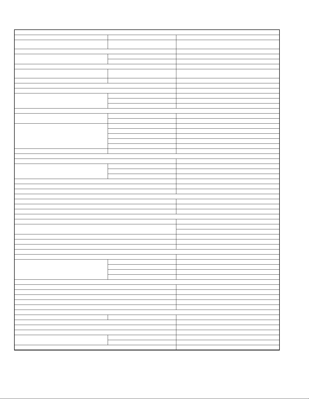
JVC KW-AVX900EU User manual

SERVICE MANUAL
COPYRIGHT © 2007 Victor Company of Japan, Limited No.MA341
2007/6
DVD RECEIVER WITH MONITOR
MA34120076SERVICE MANUALEXAD
KW-AVX900EU, KW-AVX900EE,
KW-AVX900U, KW-AVX900UN,
KW-AVX900A
COPYRIGHT © 2007 Victor Company of Japan, Limited
Lead free solder used in the board (material : Sn-Ag-Cu, melting point : 219 Centigrade)
Lead free solder used in the board (material : Sn-Cu, melting point : 230 Centigrade)
TABLE OF CONTENTS
1 PRECAUTION. . . . . . . . . . . . . . . . . . . . . . . . . . . . . . . . . . . . . . . . . . . . . . . . . . . . . . . . . . . . . . . . . . . . . . . . . 1-7
2 SPECIFIC SERVICE INSTRUCTIONS . . . . . . . . . . . . . . . . . . . . . . . . . . . . . . . . . . . . . . . . . . . . . . . . . . . . . 1-10
3 DISASSEMBLY . . . . . . . . . . . . . . . . . . . . . . . . . . . . . . . . . . . . . . . . . . . . . . . . . . . . . . . . . . . . . . . . . . . . . . 1-10
4 ADJUSTMENT . . . . . . . . . . . . . . . . . . . . . . . . . . . . . . . . . . . . . . . . . . . . . . . . . . . . . . . . . . . . . . . . . . . . . . . 1-28
5 TROUBLESHOOTING . . . . . . . . . . . . . . . . . . . . . . . . . . . . . . . . . . . . . . . . . . . . . . . . . . . . . . . . . . . . . . . . . 1-45
(for EU,EE)

1-2 (No.MA341)
SPECIFICATION
KW-AVX900EU
Design and specifications are subject to change without notice.
AMPLIFIER
Maximum Power Output Front/Rear 50 W per channel
Continuous Power Output (RMS) Front/Rear 20 W per channel into 4 Ω40 Hz to 20 000 Hz at no more than
0.8% total harmonic distortion
Load Impedance 4 Ω(4 Ωto 8 Ωallowance)
Equalizer Control Range Frequencies 60 Hz 150 Hz 400 Hz 1 kHz 2.5 kHz 6.3 kHz 15 kHz
Level ±10 dB
Signal-to-Noise Ratio 70 dB
Audio Output Level LINE OUT (FRONT/REAR)/CENTER
OUT/ SUBWOOFER
Line-Out Level/Impedance 5.0 V/20 kΩload (full scale)
Output Impedance 1 kΩ
Color System PAL
Video Output (composite) 1 Vp-p/75 Ω
Other Terminals Input LINE IN VIDEO IN CAMERA IN USB input terminal Aerial input
Output 2nd AUDIO OUT, VIDEO OUT
Others CD changer, OE REMOTE
FM/AM TUNER
Frequency Range FM 87.5 MHz to 108.0 MHz
AM (MW) 522 kHz to 1 620 kHz
(LW) 144 kHz to 279 kHz
FM Tuner Usable Sensitivity 11.3 dBf (1.0 µV/75 Ω)
50 dB Quieting Sensitivity 16.3 dBf (1.8 µV/75 Ω)
Alternate Channel Selectivity (400 kHz) 65 dB
Frequency Response 40 Hz to 15 000 Hz
Stereo Separation 35 dB
MW Tuner Sensitivity/Selectivity 20 µV/35 dB
LW Tuner Sensitivity 50 µV
DVD/CD
Signal Detection System Non-contact optical pickup (semiconductor laser)
Frequency Response DVD, fs=48 kHz 16 Hz to 22 000 Hz
DVD, fs=192 kHz 16 Hz to 88 000 Hz
VCD/CD 16 Hz to 20 000 Hz
Dynamic Range 93 dB
Signal-to-Noise Ratio 95 dB
Wow and Flutter Less than measurable limit
SD
Compatible File System FAT 32/16/12
Capacity 8 Mbytes to 2 Gbytes
Data Transfer Rate Maximum 10 Mbps
USB
USB Standards USB 1.1
Data Transfer Rate Full Speed: Maximum 12 Mbytes
Low Speed: Maximum 1.5 Mbytes
Compatible Device Mass storage class
Compatible File System FAT 32/16/12
Max. Current Less than 500 mA/5V
TV
Color System PAL/SECAM
Channel Coverage VHF: Ch 2 - 12
UHF: Ch 21 - 69
MONITOR
Screen Size 7 inch wide liquid crystal display
Number of Pixel 336 960 pixels: 480 ×3 (horizontal) ×234 (vertical)
Drive Method TFT (Thin Film Transistor) active matrix format
Color System NTSC/PAL/SECAM
Aspect Ratio 16:9 (wide)
GENERAL
Power Requirement Operating Voltage DC 14.4 V (11 V to 16 V allowance)
Grounding System Negative ground
Allowable Storage Temperature -10°C to +60°C
Allowable Operating Temperature 0°C to +40°C
Dimensions (W ×H ×D): With trim plate and sleeve at-
tached
Installation Size (approx.) 182 mm ×111 mm ×160 mm
Panel Size (approx.) 188 mm ×117 mm ×10 mm
Mass (approx.) 3 kg (including trims and sleeve)

(No.MA341)1-3
KW-AVX900EE
Design and specifications are subject to change without notice.
AMPLIFIER
Maximum Power Output Front/Rear 50 W per channel
Continuous Power Output (RMS) Front/Rear 20 W per channel into 4 Ω40 Hz to 20 000 Hz at no more than
0.8% total harmonic distortion
Load Impedance 4 Ω(4 Ωto 8 Ωallowance)
Equalizer Control Range Frequencies 60 Hz 150 Hz 400 Hz 1 kHz 2.5 kHz 6.3 kHz 15 kHz
Level ±10 dB
Signal-to-Noise Ratio 70 dB
Audio Output Level LINE OUT (FRONT/REAR)/CENTER
OUT/ SUBWOOFER
Line-Out Level/Impedance 5.0 V/20 kΩload (full scale)
Output Impedance 1 kΩ
Color System PAL
Video Output (composite) 1 Vp-p/75 Ω
Other Terminals Input LINE IN VIDEO IN CAMERA IN USB input terminal Aerial input
Output 2nd AUDIO OUT, VIDEO OUT
Others CD changer, OE REMOTE
FM/AM TUNER
Frequency Range FM 87.5 MHz to 108.0 MHz
AM (MW) 522 kHz to 1 620 kHz
(LW) 144 kHz to 279 kHz
FM Tuner Usable Sensitivity 11.3 dBf (1.0 µV/75 Ω)
50 dB Quieting Sensitivity 16.3 dBf (1.8 µV/75 Ω)
Alternate Channel Selectivity (400 kHz) 65 dB
Frequency Response 40 Hz to 15 000 Hz
Stereo Separation 35 dB
MW Tuner Sensitivity/Selectivity 20 µV/35 dB
LW Tuner Sensitivity 50 µV
DVD/CD
Signal Detection System Non-contact optical pickup (semiconductor laser)
Frequency Response DVD, fs=48 kHz 16 Hz to 22 000 Hz
DVD, fs=192 kHz 16 Hz to 88 000 Hz
VCD/CD 16 Hz to 20 000 Hz
Dynamic Range 93 dB
Signal-to-Noise Ratio 95 dB
Wow and Flutter Less than measurable limit
SD
Compatible File System FAT 32/16/12
Capacity 8 Mbytes to 2 Gbytes
Data Transfer Rate Maximum 10 Mbps
USB
USB Standards USB 1.1
Data Transfer Rate Full Speed: Maximum 12 Mbytes
Low Speed: Maximum 1.5 Mbytes
Compatible Device Mass storage class
Compatible File System FAT 32/16/12
Max. Current Less than 500 mA/5V
TV
Color System SECAM
Channel Coverage VHF: Ch 1 - 12
UHF: Ch 21 - 69
MONITOR
Screen Size 7 inch wide liquid crystal display
Number of Pixel 336 960 pixels: 480 x 3 (horizontal) ×234 (vertical)
Drive Method TFT (Thin Film Transistor) active matrix format
Color System NTSC/PAL/SECAM
Aspect Ratio 16:9 (wide)
GENERAL
Power Requirement Operating Voltage DC 14.4 V (11 V to 16 V allowance)
Grounding System Negative ground
Allowable Storage Temperature -10°C to +60°C
Allowable Operating Temperature 0°C to +40°C
Dimensions (W ×H ×D): With trim plate and sleeve at-
tached
Installation Size (approx.) 182 mm ×111 mm ×160 mm
Panel Size (approx.) 188 mm ×117 mm ×10 mm
Mass (approx.) 3 kg (including trims and sleeve)

1-4 (No.MA341)
KW-AVX900U
Design and specifications are subject to change without notice.
AMPLIFIER
Maximum Power Output Front/Rear 50 W per channel
Continuous Power Output (RMS) Front/Rear 20 W per channel into 4 Ω40 Hz to 20 000 Hz at no more than
0.8% total harmonic distortion
Load Impedance 4 Ω(4 Ωto 8 Ωallowance)
Equalizer Control Range Frequencies 60 Hz 150 Hz 400 Hz 1 kHz 2.5 kHz 6.3 kHz 15 kHz
Level ±10 dB
Signal-to-Noise Ratio 70 dB
Audio Output Level LINE OUT (FRONT/REAR)/CENTER
OUT/ SUBWOOFER
Line-Out Level/Impedance 5.0 V/20 kΩload (full scale)
Output Impedance 1 kΩ
Color System NTSC/PAL
Video Output (composite) 1 Vp-p/75 Ω
Other Terminals Input LINE IN VIDEO IN CAMERA IN USB input terminal Antenna input
Output 2nd AUDIO OUT, VIDEO OUT
Others CD changer
FM/AM TUNER
Frequency Range FM 87.5 MHz to 108.0 MHz
AM 531 kHz to 1 602 kHz
FM Tuner Usable Sensitivity 11.3 dBf (1.0 µV/75 Ω)
50 dB Quieting Sensitivity 16.3 dBf (1.8 µV/75 Ω)
Alternate Channel Selectivity (400 kHz) 65 dB
Frequency Response 40 Hz to 15 000 Hz
Stereo Separation 35 dB
AM Tuner Sensitivity/Selectivity 20 µV/35 dB
DVD/CD
Signal Detection System Non-contact optical pickup (semiconductor laser)
Frequency Response DVD, fs=48 kHz 16 Hz to 22 000 Hz
DVD, fs=192 kHz 16 Hz to 88 000 Hz
VCD/CD 16 Hz to 20 000 Hz
Dynamic Range 93 dB
Signal-to-Noise Ratio 95 dB
Wow and Flutter Less than measurable limit
SD
Compatible File System FAT 32/16/12
Capacity 8 Mbytes to 2 Gbytes
Data Transfer Rate Maximum 10 Mbps
USB
USB Standards USB 1.1
Data Transfer Rate Full Speed: Maximum 12 Mbytes
Low Speed: Maximum 1.5 Mbytes
Compatible Device Mass storage class
Compatible File System FAT 32/16/12
Max. Current Less than 500 mA/5V
TV
Color System PAL
Channel Coverage Australia VHF L: Ch 0 - 5A VHF H: Ch 6 - 12 UHF: Ch 28 - 69
New Zealand VHF L: Ch 1 - 3 VHF H: Ch 4 - 11 UHF: Ch 21 - 69
Indonesia VHF L: Ch 1A - 3 VHF H: Ch 4 - 11 UHF: Ch 21 - 69
CCIR VHF L: Ch 2 - 4 VHF H: Ch 5 - 12 UHF: Ch 21 - 69
MONITOR
Screen Size 7 inch wide liquid crystal display
Number of Pixel 336 960 pixels: 480 x 3 (horizontal) ×234 (vertical)
Drive Method TFT (Thin Film Transistor) active matrix format
Color System NTSC/PAL
Aspect Ratio 16:9 (wide)
GENERAL
Power Requirement Operating Voltage DC 14.4 V (11 V to 16 V allowance)
Grounding System Negative ground
Allowable Storage Temperature -10°C to +60°C
Allowable Operating Temperature 0°C to +40°C
Dimensions (W ×H ×D) Installation Size (approx.) 178 mm ×100 mm ×160 mm
Panel Size (approx.) 171 mm ×97 mm ×21 mm
Mass (approx.) 2.7 kg (including trims and sleeve)

(No.MA341)1-5
KW-AVX900UN
Design and specifications are subject to change without notice.
AMPLIFIER
Maximum Power Output Front/Rear 50 W per channel
Continuous Power Output (RMS) Front/Rear 20 W per channel into 4 Ω40 Hz to 20 000 Hz at no more than
0.8% total harmonic distortion
Load Impedance 4 Ω(4 Ωto 8 Ωallowance)
Equalizer Control Range Frequencies 60 Hz 150 Hz 400 Hz 1 kHz 2.5 kHz 6.3 kHz 15 kHz
Level ±10 dB
Signal-to-Noise Ratio 70 dB
Audio Output Level LINE OUT (FRONT/REAR)/CENTER
OUT/ SUBWOOFER
Line-Out Level/Impedance 5.0 V/20 kΩload (full scale)
Output Impedance 1 kΩ
Color System NTSC/PAL
Video Output (composite) 1 Vp-p/75 Ω
Other Terminals Input LINE IN VIDEO IN CAMERA IN USB input terminal Antenna input
Output 2nd AUDIO OUT, VIDEO OUT
Others CD changer
FM/AM TUNER
Frequency Range FM 87.5 MHz to 108.0 MHz
AM 531 kHz to 1 602 kHz
FM Tuner Usable Sensitivity 11.3 dBf (1.0 µV/75 Ω)
50 dB Quieting Sensitivity 16.3 dBf (1.8 µV/75 Ω)
Alternate Channel Selectivity (400 kHz) 65 dB
Frequency Response 40 Hz to 15 000 Hz
Stereo Separation 35 dB
AM Tuner Sensitivity/Selectivity 20 µV/35 dB
DVD/CD
Signal Detection System Non-contact optical pickup (semiconductor laser)
Frequency Response DVD, fs=48 kHz 16 Hz to 22 000 Hz
DVD, fs=192 kHz 16 Hz to 88 000 Hz
VCD/CD 16 Hz to 20 000 Hz
Dynamic Range 93 dB
Signal-to-Noise Ratio 95 dB
Wow and Flutter Less than measurable limit
SD
Compatible File System FAT 32/16/12
Capacity 8 Mbytes to 2 Gbytes
Data Transfer Rate Maximum 10 Mbps
USB
USB Standards USB 1.1
Data Transfer Rate Full Speed: Maximum 12 Mbytes
Low Speed: Maximum 1.5 Mbytes
Compatible Device Mass storage class
Compatible File System FAT 32/16/12
Max. Current Less than 500 mA/5V
TV
Color System PAL
Channel Coverage Australia VHF L: Ch 0 - 5A VHF H: Ch 6 - 12 UHF: Ch 28 - 69
New Zealand VHF L: Ch 1 - 3 VHF H: Ch 4 - 11 UHF: Ch 21 - 69
Indonesia VHF L: Ch 1A - 3 VHF H: Ch 4 - 11 UHF: Ch 21 - 69
CCIR VHF L: Ch 2 - 4 VHF H: Ch 5 - 12 UHF: Ch 21 - 69
MONITOR
Screen Size 7 inch wide liquid crystal display
Number of Pixel 336 960 pixels: 480 x 3 (horizontal) ×234 (vertical)
Drive Method TFT (Thin Film Transistor) active matrix format
Color System NTSC/PAL
Aspect Ratio 16:9 (wide)
GENERAL
Power Requirement Operating Voltage DC 14.4 V (11 V to 16 V allowance)
Grounding System Negative ground
Allowable Storage Temperature -10°C to +60°C
Allowable Operating Temperature 0°C to +40°C
Dimensions (W ×H ×D) Installation Size (approx.) 178 mm ×100 mm ×160 mm
Panel Size (approx.) 171 mm ×97 mm ×21 mm
Mass (approx.) 2.7 kg (including trims and sleeve)

1-6 (No.MA341)
KW-AVX900A
Design and specifications are subject to change without notice.
AMPLIFIER
Maximum Power Output Front/Rear 50 W per channel
Continuous Power Output (RMS) Front/Rear 20 W per channel into 4 Ω40 Hz to 20 000 Hz at no more than
0.8% total harmonic distortion
Load Impedance 4 Ω(4 Ωto 8 Ωallowance)
Equalizer Control Range Frequencies 60 Hz 150 Hz 400 Hz 1 kHz 2.5 kHz 6.3 kHz 15 kHz
Level ±10 dB
Signal-to-Noise Ratio 70 dB
Audio Output Level LINE OUT (FRONT/REAR)/CENTER
OUT/ SUBWOOFER
Line-Out Level/Impedance 5.0 V/20 kΩload (full scale)
Output Impedance 1 kΩ
Color System NTSC/PAL
Video Output (composite) 1 Vp-p/75 Ω
Other Terminals Input LINE IN VIDEO IN CAMERA IN USB input terminal Aerial input
Output 2nd AUDIO OUT, VIDEO OUT
Others CD changer
FM/AM TUNER
Frequency Range FM 87.5 MHz to 108.0 MHz
AM 531 kHz to 1 602 kHz
FM Tuner Usable Sensitivity 11.3 dBf (1.0 µV/75 Ω)
50 dB Quieting Sensitivity 16.3 dBf (1.8 µV/75 Ω)
Alternate Channel Selectivity (400 kHz) 65 dB
Frequency Response 40 Hz to 15 000 Hz
Stereo Separation 35 dB
AM Tuner Sensitivity/Selectivity 20 µV/35 dB
DVD/CD
Signal Detection System Non-contact optical pickup (semiconductor laser)
Frequency Response DVD, fs=48 kHz 16 Hz to 22 000 Hz
DVD, fs=192 kHz 16 Hz to 88 000 Hz
VCD/CD 16 Hz to 20 000 Hz
Dynamic Range 93 dB
Signal-to-Noise Ratio 95 dB
Wow and Flutter Less than measurable limit
SD
Compatible File System FAT 32/16/12
Capacity 8 Mbytes to 2 Gbytes
Data Transfer Rate Maximum 10 Mbps
USB
USB Standards USB 1.1
Data Transfer Rate Full Speed: Maximum 12 Mbytes
Low Speed: Maximum 1.5 Mbytes
Compatible Device Mass storage class
Compatible File System FAT 32/16/12
Max. Current Less than 500 mA/5V
TV
Color System PAL
Channel Coverage Australia VHF L: Ch 0 - 5A VHF H: Ch 6 - 12 UHF: Ch 28 - 69
New Zealand VHF L: Ch 1 - 3 VHF H: Ch 4 - 11 UHF: Ch 21 - 69
Indonesia VHF L: Ch 1A - 3 VHF H: Ch 4 - 11 UHF: Ch 21 - 69
CCIR VHF L: Ch 2 - 4 VHF H: Ch 5 - 12 UHF: Ch 21 - 69
MONITOR
Screen Size 7 inch wide liquid crystal display
Number of Pixel 336 960 pixels: 480 x 3 (horizontal) ×234 (vertical)
Drive Method TFT (Thin Film Transistor) active matrix format
Color System NTSC/PAL
Aspect Ratio 16:9 (wide)
GENERAL
Power Requirement Operating Voltage DC 14.4 V (11 V to 16 V allowance)
Grounding System Negative ground
Allowable Storage Temperature -10°C to +60°C
Allowable Operating Temperature 0°C to +40°C
Dimensions (W ×H ×D) Installation Size (approx.) 178 mm ×100 mm ×160 mm
Panel Size (approx.) 171 mm ×97 mm ×21 mm
Mass (approx.) 2.7 kg (including trims and sleeve)

(No.MA341)1-7
SECTION 1
PRECAUTION
1.1 Safety Precautions
!Burrs formed during molding may be left over on some parts of the chassis. Therefore,
pay attention to such burrs in the case of preforming repair of this system.
!Please use enough caution not to see the beam directly or touch it in case of an
adjustment or operation check.

1-8 (No.MA341)
1.2 Preventing static electricity
Electrostatic discharge (ESD), which occurs when static electricity stored in the body, fabric, etc. is discharged, can destroy the laser
diode in the traverse unit (optical pickup). Take care to prevent this when performing repairs.
1.2.1 Grounding to prevent damage by static electricity
Static electricity in the work area can destroy the optical pickup (laser diode) in devices such as laser products.
Be careful to use proper grounding in the area where repairs are being performed.
(1) Ground the workbench
Ground the workbench by laying conductive material (such as a conductive sheet) or an iron plate over it before placing the
traverse unit (optical pickup) on it.
(2) Ground yourself
Use an anti-static wrist strap to release any static electricity built up in your body.
(3) Handling the optical pickup
• In order to maintain quality during transport and before installation, both sides of the laser diode on the replacement optical
pickup are shorted. After replacement, return the shorted parts to their original condition.
(Refer to the text.)
• Do not use a tester to check the condition of the laser diode in the optical pickup. The tester's internal power source can easily
destroy the laser diode.
1.3 Handling the traverse unit (optical pickup)
(1) Do not subject the traverse unit (optical pickup) to strong shocks, as it is a sensitive, complex unit.
(2) Cut off the shorted part of the flexible cable using nippers, etc. after replacing the optical pickup. For specific details, refer to the
replacement procedure in the text. Remove the anti-static pin when replacing the traverse unit. Be careful not to take too long a
time when attaching it to the connector.
(3) Handle the flexible cable carefully as it may break when subjected to strong force.
(4) It is not possible to adjust the semi-fixed resistor that adjusts the laser power. Do not turn it.
1.4 Attention when traverse unit is decomposed
*Please refer to "Disassembly method" in the text for the pickup unit.
• Apply solder to the short land before the card wire is disconnected from the connector on the pickup unit.
(If the card wire is disconnected without applying solder, the pickup may be destroyed by static electricity.)
• In the assembly, be sure to remove solder from the short land after connecting the card wire.
1M
(caption)
Anti-static wrist strap
Conductive material
(conductive sheet) or iron plate
Mechanism control board
CN101
Flexible wire
Short-circuit points

(No.MA341)1-9
1.5 Important for laser products
1.CLASS 1 LASER PRODUCT
2.CAUTION :
(For U.S.A.) Visible and/or invisible class II laser radiation
when open. Do not stare into beam.
(Others) Visible and/or invisible class 1M laser radiation
when open. Do not view directly with optical instruments.
3.CAUTION : Visible and/or invisible laser radiation when
open and inter lock failed or defeated. Avoid direct
exposure to beam.
4.CAUTION : This laser product uses visible and/or invisible
laser radiation and is equipped with safety switches which
prevent emission of radiation when the drawer is open and
the safety interlocks have failed or are defeated. It is
dangerous to defeat the safety switches.
5.CAUTION : If safety switches malfunction, the laser is able
to function.
6.CAUTION : Use of controls, adjustments or performance of
procedures other than those specified here in may result in
hazardous radiation exposure.
REPRODUCTION AND POSITION OF LABELS and PRINT
!Please use enough caution not to
see the beam directly or touch it
in case of an adjustment or operation
check.
WARNING LABEL and PRINT

1-10 (No.MA341)
SECTION 2
SPECIFIC SERVICE INSTRUCTIONS
This service manual does not describe SPECIFIC SERVICE INSTRUCTIONS.
SECTION 3
DISASSEMBLY
3.1 Main body
3.1.1 Removing the FRONT PANEL assembly (See Fig.1 to
4)
(1) From the bottom side of main body, insert the screwdriver
to hole of the third gear from hole a of the bottom chassis,
and then turn the gear to clockwise until FRONT PANEL
assembly comes up. (See Fig.1)
(2) Remove the two screws Aattaching the both side of the
FRONT PANEL assembly. (See Fig.2)
(3) Remove the four screws Battaching the both side of the
FRONT PANEL assembly. (See Fig.2)
(4) Remove the one screw Cattaching the FPC GUIDE. (See
Fig.3)
(5) Remove the one screw Dattaching the FRONT CHASSIS.
(See Fig.3)
(6) Disconnect the card wire from MONITOR assembly con-
nected to connector CN401 of the PANEL BOARD assem-
bly. (See Fig.4)
(7) Disengage two hooks aengaged FRONT CHASSIS. (See
Fig.2)
Fig.1
Fig.2
hole a
BB
AA
hook a
hook a

(No.MA341)1-11
Fig.3
Fig.4
3.1.2 Removing the HEAT SINK (See Fig.5)
(1) Remove the four screws Eand three screws Fattaching
the HEAT SINK.
Fig.5
C
CN401
D
E
EF

1-12 (No.MA341)
3.1.3 Removing the REAR BRACKET (See Fig.6, 7)
(1) Remove the three screws Gattaching the REAR HEAT
SINK. (See Fig.6)
(2) Remove the thirteen screws Hattaching the REAR
BRACKET. (See Fig.6)
(3) Disconnect the connector wire from FAN connected to con-
nector CN906 of the SUB BOARD assembly. (See Fig.7)
(4) Disconnect the connector wire from USB CABLE connect-
ed to connector CN911 of the SUB BOARD assembly.
(See Fig.7)
Fig.6
Fig.7
HHG H
CN906
CN911

(No.MA341)1-13
3.1.4 Removing the TOP CHASSIS assembly (See Fig.8 to 11)
(1) Disconnect the card wire from TOP CHASSIS assembly
connected to connector CN702 of the MAIN BOARD as-
sembly. (See Fig.8)
(2) Remove the two screws Jattaching the FRONT BOARD
assembly. (See Fig.8)
(3) Disconnect the connector wire from MAIN BOARD assem-
bly connected to connector CN902 of the SUB BOARD as-
sembly. (See Fig.9)
(4) Disconnect the card wire from MAIN BOARD assembly
connected to connector CN904 of the SUB BOARD as-
sembly. (See Fig.9)
(5) From left side of MAIN BODY, remove the two screws Kat-
taching the TOP CHASSIS assembly. (See Fig.10)
(6) From right side of MAIN BODY, remove the two screws L
attaching the TOP CHASSIS assembly. (See Fig.11) Fig.8
Fig.9
Fig.10
Fig.11
CN702 J
CN904 CN902
K
K
LL

1-14 (No.MA341)
3.1.5 Removing the MAIN BOARD assembly (See Fig.12)
(1) Disconnect the connector wire from the MECHA SWITCH
BOARD assembly connected to connector CN764 of the
MAIN BOARD assembly.
(2) Remove the four screws Mattaching the MAIN BOARD as-
sembly.
Fig.12
3.1.6 Removing the MID CHASSIS (See Fig.13)
(1) Remove the four screws Nattaching the MID CHASSIS.
Fig.13
CN764
MM
NN

(No.MA341)1-15
3.1.7 Removing the SUB BOARD assembly (See Fig.14, 15)
(1) Disconnect the card wire from CONNECTION BOARD as-
sembly connected to connector CN907 of the SUB BOARD
assembly. (See Fig.14)
(2) Disconnect the card wire from SUB BOARD assembly con-
nected to connector CN901 of the TV TUNER BOARD as-
sembly. (See Fig.15)
(3) Remove the five screws Pattaching the SUB BOARD as-
sembly. (See Fig.15)
Fig.14
Fig.15
CN907
P
CN901

1-16 (No.MA341)
3.1.8 Removing the TV TUNER BOARD assembly (See Fig.16 to 18)
(1) Remove the two screws Qattaching the FRONT PCB
BRACKET. (See Fig.16)
(2) Remove the three screws Rattaching the SUB PCB
BRACKET. (See Fig.17)
(3) Remove the one screw Sattaching the TV TUNER BOARD
assembly. (See Fig.18)
Fig.16
Fig.17
Fig.18
Q
R
S

(No.MA341)1-17
3.1.9 Removing the DVD MECHANISM assembly (See Fig.19)
(1) Remove the three screws Tattaching the DVD MECHA-
NISM assembly.
Fig.19
3.1.10 Removing the CONNECTION BOARD assembly (See Fig.20)
(1) Takeout the INSULATOR.
(2) Disconnect the card wire from FRONT END BOARD as-
sembly connected to connector CN301 and CN303 of the
CONNECTION BOARD assembly.
(3) Remove the four screws Uattaching the CONNECTION
BOARD assembly.
Fig.20
T
CN303
CN301
U
U

1-18 (No.MA341)
3.2 Monitor section
3.2.1 Removing the FRONT BRACKET assembly (See
Fig.1)
(1) Remove the two screws Aattaching the FPC COVER.
(2) Remove the four screws Battaching the FRONT BRACK-
ET assembly.
(3) Remove the two screws Cattaching the FRONT BRACK-
ET assembly.
Fig.1
3.2.2 Removing the PANEL BOARD assembly (See Fig.2)
(1) Disconnect the connector wire from LCD module connect-
ed to connector CN471 of the PANEL BOARD assembly.
(2) Disconnect the card wire from SWITCH BOARD assembly
connected to connector CN431, CN511 and CN591 of the
PANEL BOARD assembly.
(3) Remove the four screws Dattaching the PANEL BOARD
assembly.
(4) Straighten hook aattaching the PANEL BOARD assembly.
Fig.2
3.2.3 Removing the LCD module (See Fig.3)
(1) Remove the six screws Eattaching the PANEL BRACKET
assembly. (See Fig.3)
(2) Disengage seven hooks bengaged PANEL BRACKET.
Fig.3
B
B
C
A
DD
CN431 CN511 CN591
CN471hook a
hook bhook b
hook b
E
EE
E

(No.MA341)1-19
3.3 DVD mechanism assembly
3.3.1 Removing the mechanism control board
(See Fig.1)
Caution:
Before disconnecting the flexible wire extending from the DVD
pickup, solder the short-circuit point on the flexible wire using
a grounding soldering iron. If you do not follow this instruction,
the DVD pickup may be damaged.
(1) Turn over the body, and solder the short-circuit points on
the flexible wire extending from the DVD pickup.
(2) Disconnect the flexible wire from connector CN101 on the
mechanism control board.
(3) Disconnect the card wire from connector CN201 on the
mechanism control board.
(4) Disconnect the flexible wire from connector CN202 on the
mechanism control board.
(5) Unsolder two soldered points aon the mechanism control
board and remove the wire extending from the feed motor.
(6) Remove the screw Aattaching the lug wire.
(7) Remove the two screws Band screw Cattaching the
mechanism control board.
Caution:
• As the flexible wire to be connected to CN101, make sure to
attach it to the mechanism control board using a double
tape.
• After reassembling, unsolder the short-circuit points.
Fig.1
Double tape
Feed motor
Mechanism control board
CN202
CN101
B
a
C
B
CN201
Flexible wire
Short-circuit points
A
Lug wire

1-20 (No.MA341)
3.3.2 Removing the top cover
(See Fig.2)
(1) Remove the two screws Dattaching the top cover on the
back of the body.
(2) Remove the top cover upward.
Reference:
When reassembling, set part bof the top cover under the
bending part cof the chassis frame.
3.3.3 Removing the mechanism section
(See Fig.2 to 4)
• Remove the top cover.
(1) From the bottom of the body, remove the screw Eattaching
the lug wire. (See Fig.2.)
(2) Remove the two screws Fattaching the right and left stop-
pers on the front side. (See Fig.2.)
(3) Remove the two floating springs on the bottom of the body.
(See Fig.3.)
(4) Move the mechanism section upward and remove from the
chassis frame.
The three damper springs come off from the dampers.
(See Fig.4.)
Caution:
• When reassembling, reattach the damper spring to the
damper respectively and insert the three shafts on the bot-
tom of the mechanism to the dampers.
• Before inserting the shaft to the dampers, apply IPA to the
hole of damper.
Fig.2
Fig.3
Fig.4
D
Top cover
Stopper
Stopper
F
F
b
cE
Lug wire
D
Floating spring
Mechanism section
Damper (R)
(Purple)
Damper (F)
(Black)
Damper (F)
(Black)
Chassis frame
Damper SP.(F)
(Silver)
Damper SP.(F)
(Silver)
Damper SP.(R)
(Red)
This manual suits for next models
11
Table of contents
Other JVC Receiver manuals

JVC
JVC RX-7030VBK User manual

JVC
JVC KD-AVX1 User manual

JVC
JVC RXD401S - AV / Digital Multimedia Receiver User manual

JVC
JVC KD-AVX11 - EXAD - DVD Player Guide

JVC
JVC KD-SX38MBT User manual

JVC
JVC RX-201SUN User manual

JVC
JVC KD-X472BT User manual

JVC
JVC RX-111BK User manual

JVC
JVC KD-X176 User manual

JVC
JVC KD-X120EE User manual