9
Compressor Features
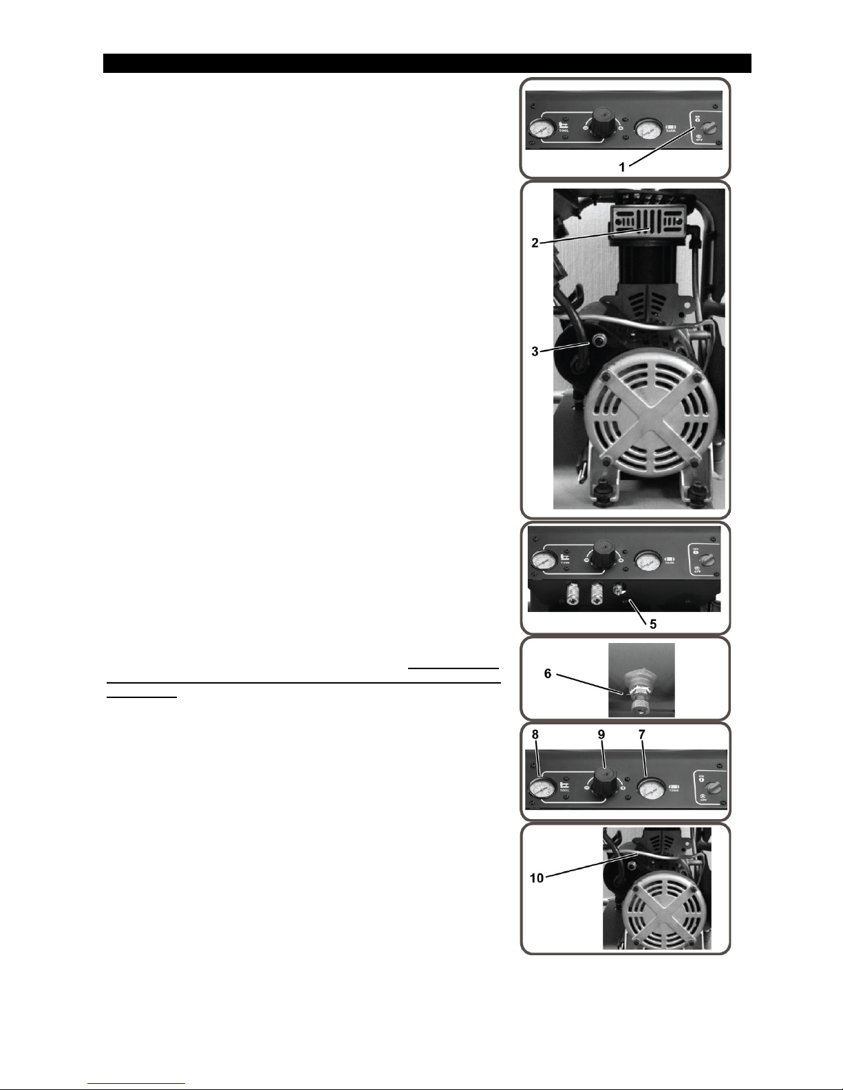
1) Motor/Pressure Switch:This switch is used to start or stop the air
compressor. Moving the switch to the ON (1) position will provide
automatic power to the pressure switch which will allow the motor to
start when the air tank pressure is below the factory set cut-in pressure.
When in the ON (1) position, the pressure switch stops the motor
when the air tank pressure reaches the factory set cut-
safety purposes, this switch also has a pressure release valve located
on the side of the switch designed to automatically release compressed
air from the air compressor pump head and its discharge line when the
air compressor reaches cut-out pressure or is shut off. This allows the
motor to restart freely. Moving the switch to the OFF (0) position will
remove power from the pressure switch and stop the air compressor.
2) Motor Thermal Overload:Motor has a protective breaker located
on the pump. Excessive amperage draw will result in the breaker
tripping to protect the motor and operator. Reset the breaker by pushing
the black plastic stem back into the housing. Reset switch if it is tripped.
3) Air Intake Filter:This filter is designed to clean air coming into the
pump. To ensure the pump continually receives a clean, cool, dry air
supply, this filter must always be clean and ventilation opening free
from obstructions. The filter can be removed for cleaning by using
warm, soapy water. Rinse the filter and air dry.
4) Air Compressor Pump:To compress air, the piston moves up and
down in the cylinder. On the downstroke, air is drawn in through the air
intake valve while the exhaust valve remains closed. On the upstroke,
air is compressed, the intake valve closes and compressed air is forced
out through the exhaust valve, into the discharge line, through the
check valve and into the air tank.
5) Safety Relief Valve:This valve is designed to prevent system
fa
ilures by relieving pressure from the system when the compressed air
reaches a predetermined level. The valve is preset by the manufacturer
and must not be modified in any way. To verify the valve is working
properly, pull on the ring. Air pressure should escape. When the ring is
released, it will reseat.
6) Air Tank Drain Valve:The drain valve is used to remove moisture
from the air tank(s) after the air compressor is shut off.
to open the drain valve when more than 0.7 bar
the air tank! To open the drain valve, turn the knob counter-clockwise.
Tilt tank to ensure that all condensation drains through valve.
7) Air Tank Pressure Gauge:The air tank pressure gauge indicates
the reserve air pressure in the air tank(s).
8) Outlet Pressure Gauge:
The outlet pressure gauge indicates the air
pressure available at the outlet side of the regulator. This pressure is
controlled by the regulator and is always less or equal to the air tank
pressure.
9) Pressure Regulator:The air pressure coming from the air tank is
controlled by the regulator knob. Turn the pressure regulation knob
clockwise to increase discharge pressure, and counter-clockwise to
decrease discharge pressure. Follow tool operating instructions for
recommended pressure range.
10) Discharge Line: Please note that the discharge line is very hot.
HOT SURFACES: Do not remove protective shroud. High
temperature after sustained use.