Seneca R-GWR-IP-1 User manual

INSTALLATION MANUAL
R-GWR SENSORS
Industrial sensor and home automation sensor with
digital/analogue input and anti-ooding sensor
EN
MI00549-2-EN 1/8
DOCUMENTATION
SENECA s.r.l.
Via Austria, 26 – 35127 – PADOVA – ITALY
Tel. +39.049.8705355 - 8705359 - Fax +39.049.8706287
For manuals in other languages and the conguration software,
visit www.seneca.it/products/r-gwr
R-GWR-IP-1
R-GWR-S-1

MODULE LAYOUT
2/8
Dimensions (LxHxD) 70 x 50 x 25 Weight 45 g Case Self-extinguishing UL94-V0 PC / ABS material
Dimensions (LxHxD) 80 x 65 x 45 Weight 150 g Case Self-extinguishing UL94-V0 PC / ABS material
LED MEANING
LED STATUS LED meaning
Tx (Red) Flashing Transmission of radio packets to the R-GWR gateway
Rx (Green) Flashing Reception of radio packets from the R-GWR gateway
80 mm 45 mm
65 mm
70 mm 25 mm
50 mm
WARNING: The full content of this manual must be read before any operation. The module must only be used by
qualied electricians. Specic documentation is available via QR-CODE shown on page 1.
Electrical and electronic waste disposal (applicable in the European Union and other countries with recycling).
The symbol on the product or its packaging shows the product must be surrendered to a collection centre
authorized to recycle electrical and electronic waste.
The module must be repaired and damaged parts replaced by the Manufacturer. The product is sensitive to
electrostatic discharges. Take appropriate measures during any operation.
PRELIMINARY WARNINGS
The word WARNING preceded by the symbol indicates conditions or actions that put the user's safety at risk.
The word ATTENTION preceded by the symbol indicates conditions or actions that might damage the
instrument or the connected equipment. The warranty shall become null and void in the event of improper use or
tampering with the module or devices supplied by the manufacturer as necessary for its correct operation, and if
the instructions contained in this manual are not followed.
N.B: THE LEDS, IN BOTH SENSORS, ARE PLACED INSIDE THE BOX. THEY ARE NOT VISIBLE FROM THE OUTSIDE.

TECHNICAL SPECIFICATIONS
STANDARDS
ETSI EN 301 489-1 v.2.2.3
ETSI EN 301 409-3 v.2.1.1
EN 60950
ETSI 300 220-2 v3.2.1
POWER SUPPLY
3 V lithium battery type: CR2: R-GWR-S-1 home automation sensor
CR123A: R-GWR-IP-1 industrial sensor
To check battery life, see user manual.
CONNECTIONS
Screw terminals, 2-way removable screw terminals, 3.5 mm pitch (*)
Anti-ooding probe connector (R-GWR-S-1 home automation sensor)
(*) With 1.5 mm2 max cable section
ENVIRONMENTAL
CONDITIONS
Operating temperature
Humidity
Storage temperature
Protection rating
From -25 °C to +70 °C
10% ÷ 90% non condensing.
From -40 °C to +85 °C
IP20 / IP40
ASSEMBLY Wall using screws or double-sided tape
RADIO TECHNOLOGY LoRa ®
FREQUENCY BAND
Frequency band: 863÷865 MHz,
Rated frequency: 863.11 MHz,
Bandwidth 25 KHz,
SENSITIVITY Up to -146 dBm
MAX RF POWER + 14 dBm
SENSOR PAIRING Maximum number of sensors that can be paired: 32
DIGITAL INPUT / ANALOG INPUT / COUNTERS
DIGITAL INPUT For potential-free contact
ANALOG INPUT Entry: 0 ÷ 30 V; precision: 0,5%
COUNTERS Number of counters: 1; Maximum frequency: 1 Hz
SENSOR FUNCTIONS
R-GWR-IP-1
INDUSTRIAL SENSOR
Temperature detection: -25 ÷ 70°C, Precision: 0.5°C between 5 ÷ 60°C
Moisture percentage detection: 0 ÷ 100%, Precision: 3% between 20 ÷ 80% R.H.
1 analogue/digital input
Analogue input: measurement range 0-30V; Precision: +/- 0.15 V
R-GWR-S-1
HOME AUTOMATION
SENSOR
Temperature detection: -25 ÷ 70°C, Precision: 0.5°C between 5 ÷ 60°C
Moisture percentage detection: 0 ÷ 100%, Precision: 3% between 20 ÷ 80% R.H.
Anti-tamper button
1 analogue/digital input
Analogue input: measurement range 0-30V; Precision: +/- 0.15 V
1 reed relay (to control the opening of compartments and rooms)
1 anti-ooding probe (optional)
3/8

4/8
PAIRING PROCEDURE
1. The R-GWR device can be paired with a maximum of 32 sensors.
2. A paired sensor is enabled for data exchange with the Gateway.
3. To pair one or more new sensors it is necessary to follow the procedure below:
4.
5. Power up the R-GWR gateway and the radio sensor
6. In the gateway press the “START NEW SENSOR PAIRING” button in the “Status” section of the web server.
7. The STS LED of the gateway will start ashing.
8. In the sensor you want to pair, press and hold the pairing button until the red LED lights up (transmission).
9. If the green LED of the radio sensor (radio reception) lights up, the association was successful and the new
sensor with its data will appear in the “Status” section of the R-GWR gateway web server.
10. Press the pairing buttons of each sensor you want to pair as in the previous point
11. Once all the sensors have been paired, press the “STOP NEW SENSOR PAIRING” button in the R-GWR
web server “status” section.
12. The STS LED of the R-GWR gateway stops ashing.
The procedure for replacing a sensor is given in the user manual.
WALL MOUNTING
To x the sensors to the wall follow the procedure below:
R-GWR-S-1 home automation sensor:
Use a Phillips screwdriver and remove the screws (reference 1 and 2 shown on page 5);
Use a Phillips screwdriver and remove the PCB fixing screw (if the battery is installed, remove the battery in order
to reach the PCB fixing screw);
Remove the PCB, taking care not to damage it;
Use the holes on the bottom of the sensor as references to drill the support;
Insert the supplied dowels;
Fix the sensor base with the supplied screws;
Reposition the printed circuit and fix it with the previously removed screw;
Replace the cover and tighten the screws firmly all the way.
R-GWR-IP-1 industrial sensor:
Use a Phillips screwdriver and remove the screws (reference 1 and 2 shown on page 5);
Use the holes on the bottom of the sensor as references to drill the support;
Insert the supplied dowels;
Fix the sensor base with the supplied screws;
Replace the cover and tighten the screws firmly all the way.
R-GWR-IP-1 industrial sensor:
R-GWR-S-1 home automation sensor:

5/8
BATTERY REPLACEMENT
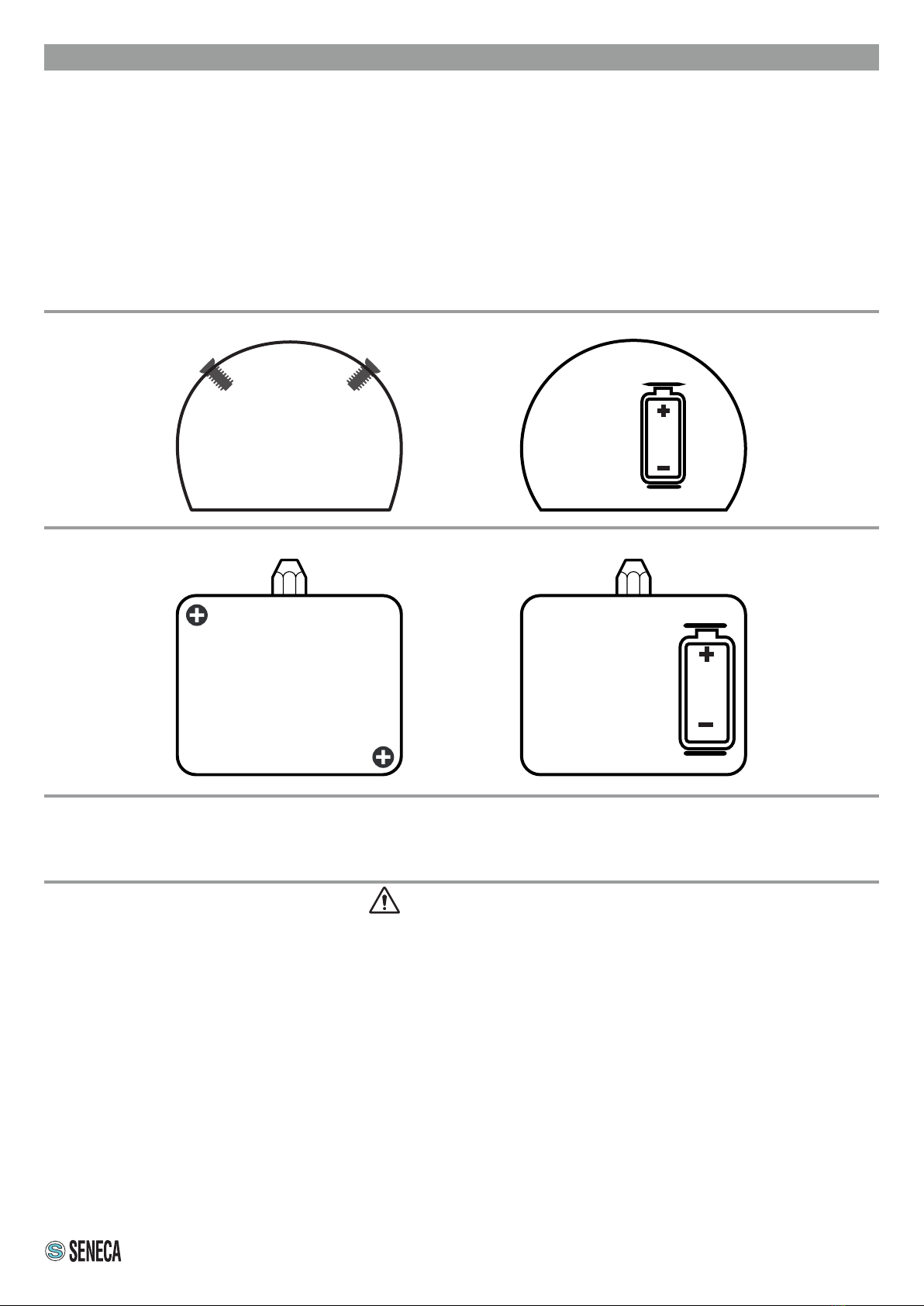
Use a Phillips screwdriver and remove the screws (reference 1 and 2).
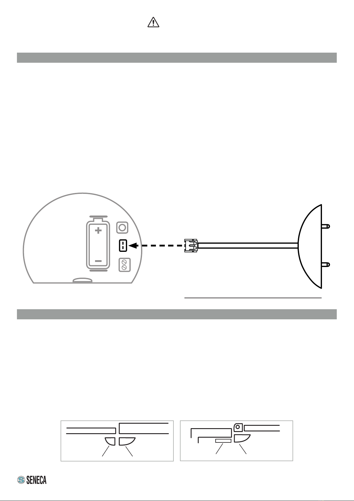
Open the top cover, remove the battery and insert a new battery (CR123A type for the R-GWR-IP-1 sensor and
CR2 type for the R-GWR-S-1 sensor) with the correct polarity (see following image).
Replace the cover and tighten the screws firmly all the way.
Do not overtighten the screws to avoid breaking the cover.
Pairing begins automatically and the Rx led starts flashing.
Note:
- Do not lose the cover and screws.
- The battery supplied at the time of purchase may have a shorter life span, as it is installed at the factory to
check performance
R-GWR-IP-1 INDUSTRIAL SENSOR
CAUTION
• Do not use sharp objects to remove the battery.
• Old batteries cannot be disposed of in household waste, it is mandatory to return them to the appropriate collection
place, prepared by the municipality or point of sale.
• Spent batteries contain heavy metals or material harmful to the environment and health.
• Since they also contain important elements such as iron, zinc, manganese and nickel, they can be recycled.
• We recommend using batteries of the same type inside a device, the use of batteries of different types could cause
liquid leakage or battery breakage, or damage the device in use.
• Always replace the battery or batteries of the device used with batteries of the size and type specied by the
manufacturer.
• Do not apply pressure or shocks to the battery, this might damage it and cause liquid leakage or breakage.
• Do not expose the instrumentation to extreme, high or low temperatures or pressures, this might cause an explosion or
leakage of ammable liquids or gases.
• In the presence of odours, swellings, cracks or loose or missing caps, the batteries must be considered “damaged”.
Damaged batteries can release dangerous chemicals and require a special disposal process.
• Contact the manufacturer's customer service for advice on treating damaged batteries.
1
2
1 2
R-GWR-S-1 HOME AUTOMATION SENSOR
(*) If it is necessary to switch off the R-GWR control unit for a long period, we advise you to switch off the sensors by removing the
batteries.
Failure to remove the battery would lead to its depletion due to multiple attempts by the single sensor to connect to the control unit.
N.B.: To remove the battery, follow the instructions above.

6/8
ELECTRICAL CONNECTIONS
DIGITAL INPUT
ANALOGUE INPUT
SENSOR OPERATION
1
2
4
3
5
1
3
2
HOME AUTOMATION SENSOR
INDUSTRIAL SENSOR
KEY:
1) Housing for the battery
2) Button used to pair the sensor and force communication with
the R-GWR control unit
3) Analogue / digital input connection terminal
4) Clamp used to connect the anti-ooding probe
5) Input dedicated to monitoring the opening of doors and/or
windows.
KEY:
1) Housing for the battery
2) Button used to pair the sensor and force communication with
the R-GWR control unit
3) Analogue / digital input connection terminal
4) Clamp for connecting the additional battery pack.
It is an ON/OFF terminal type input, through this contact you can
check the status of a device connected to the sensor and monitor
its switching on and off via the web server.
It is an input that allows you to monitor the operation of a machine
or device with a measurement range that can go from a minimum
of 0 VDC to a maximum of 30 VDC.
The polarity of the terminal must comply with the diagram shown
on the side.
Terminal 4
Terminal 4
4

7/8
ANTI-FLOOD PROBE ACCESSORY (ONLY FOR R-GWR-S-1 HOME AUTOMATION SENSOR)
Using this accessory, which can be ordered at www.seneca.it/prodotti/r-gwr in the accessories section, it is possible
to monitor the presence of water in the rooms where it is placed.
For correct operation, place the probe at oor level with the metal sensors facing downwards.
The procedure for connecting the anti-ooding sensor to the standard home automation sensor is shown below:
Use a Phillips screwdriver and remove the screws as per the battery replacement procedure.
Open the top cover and connect the two-pole male connector (reference 2) to the terminal (reference 1) as shown
in the image;
Close the sensor by replacing the cover with the pre-drilled one supplied with the anti-flooding probe accessory.
Do not overtighten the screws to avoid breaking the cover.
Pairing begins automatically and the Rx led starts flashing.
1
2
SENSOR PROBE
70 cm
CAUTION
Before using a sensor, it is necessary to set the conguration using the “SETUP” button via web
server. The setting procedure is described in the user manual.
MONITORING OF DOOR AND WINDOW OPENING
To install the sensor follow the procedure below:
1. Identify the installation point of both the sensor and the magnet (e.g.: door frame, upright, window frame),
evaluate the use of the type 1 or type 2 magnet depending on your requirements and clean the two identied
areas;
2. Apply the round Velcro patch onto the magnet;
3. Check it is positioned correctly and, to guarantee it works properly, leave a maximum distance of 10 mm
between the two elements;
4. Remove the Velcro protection lm from both the sensor and the magnet, apply in the two areas identied,
pressing lightly for a few seconds.
SensorType 2 magnet
SensorType 1 magnet

8/8
If the Tx Green LED does not light up, there may be four reasons:
1) the sensor is not yet paired with the R-GWR gateway;
2) The sensor is positioned beyond the maximum distance to allow communication with the R-GWR gateway;
3) the R-GWR gateway is off.
4) the sensor battery is low.
NB: it is always possible to force sending the data packet from the sensor by pressing the pairing button indicated
in the sensor operation diagram shown on page 6.
TROUBLESHOOTING
CONTACT INFORMATION
This document is the property of SENECA srl. Copies and reproduction are prohibited unless authorised.
The content of this document corresponds to the described products and technologies.
Stated data may be modied or supplemented for technical and/or sales purposes.
This manual suits for next models
1
Table of contents
Other Seneca Accessories manuals