Sure Electronics CPL-312C24 User manual
CPL-312C24
Operation and Specification SUREN
©2011 SUREN Systems, Ltd.. All rights reserved. SUREN™, HDIR™ are trademarks of SUREN. SUREN Part no.: N-ML00-0065-11-1 Rev.1 Printed in China
w w w. s u r e n s y s t e m s . c o m
TM
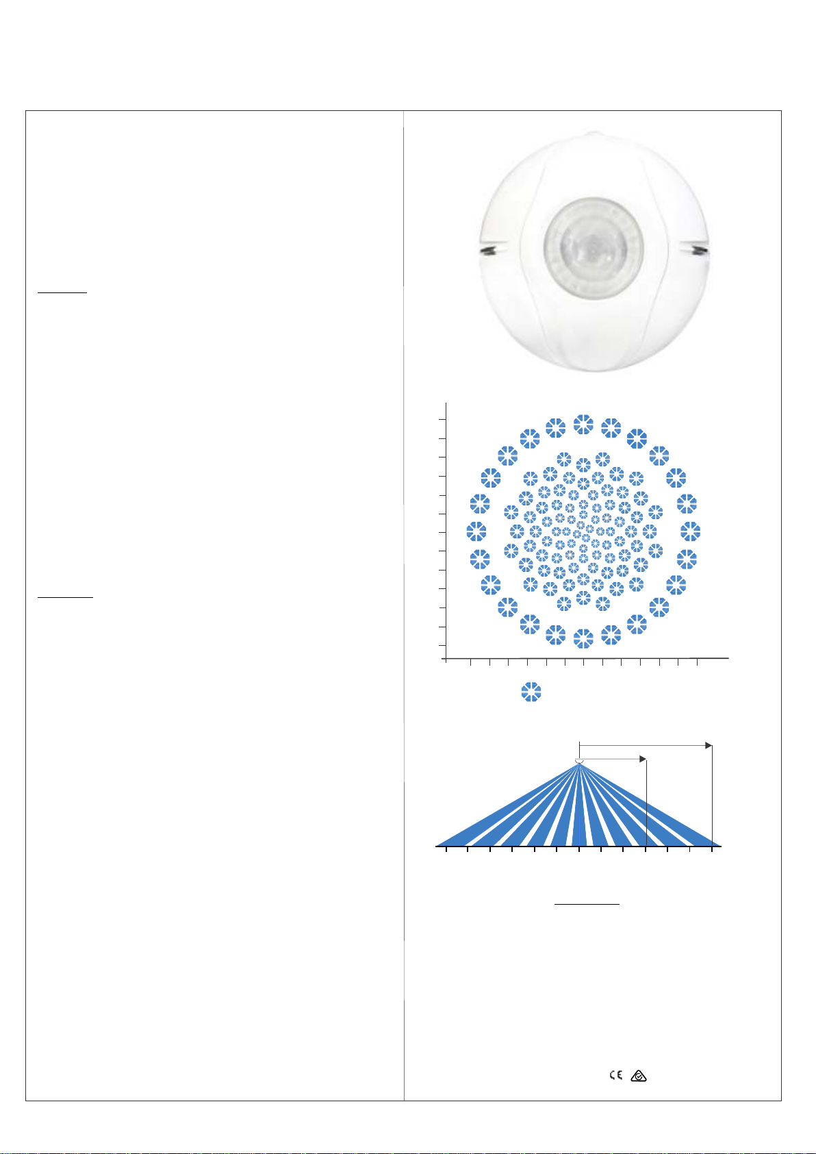
Patented HDIR Presence Sensor
CPL-312C24 is a motion sensor with SUREN's proprietary 8-element
pyros and multi-segment lens array. Mounted at a height of 2.4m, CPL-
312C24 not only offers detection of minor motion, e.g. hand movement,
within the 6m diameter area but also detection of people walking within
the area of 12m diameter.
CPL-312C24 can be surface mounted or flush mounted for an attractive,
un-obstructive appearance. One or many sensors can be connected
with Suren's (or compatible) power packs to control a wide range of load
types, including lighting or HVAC devices.
Operation
Initialization:
The sensor becomes operational 30 seconds after power is supplied.
Detection and Activation:
When a person enters a room, the sensor detects major body motion
and turns the light on. The light is kept on even as minor motion, e.g.
hand movement is detected. The sensor's Detection Sequence Logic
(DSL) minimizes false triggering by adjusting detection sensitivity
based upon sequence of presence events. The Sunset Sensor provides
additional control such that lighting is not activated when there is
sufficient brightness in the area.
De-Activation (Normal Occupancy Mode):
When motion is no longer detected, the sensor turns the light off after a
set time delay (Delayed-Off Time).
Walk-thru Mode:
The walk-through feature is useful in areas that are momentarily
occupied, e.g. hallway. If the sensor detects no movement for more than
10 seconds light was turned off, it will apply a Delayed-Off Time of 2.5
minutes. If the sensor detects movement less than 10 seconds after light
was turned off, it will next turn the light off based upon the set time delay.
Installation
Accessories:
·Brackets, screws and wall plugs for surface mount in solid ceiling
·Spring clips for flush mount in drop ceiling
·Infrared zone mask
Location:
·Determine the number of sensors required to cover the floor area
·Install the sensor near work area where walk-path cuts across radial
lines, not towards the sensor
·Do not install the sensor near ventilation outlet
Procedure:
·Prepare sensor mount. See illustration in the next page
·Connect the sensor as shown in the wiring diagram. Make sure
power supply is turned off
·Make sure there are no wiring exposed before mounting the sensor
·Mount the sensor and turn on the power supply
·Open the cover, review settings and change if necessary. See
Settings section
·Initiate test mode, replace the cover and conduct walk-test
Walk-Test:
·Toggle dip switch B3 (Off-On-Off) to enter test mode. If B3 is already
in the On position, moving it to the Off position will also activate test
mode
·Amber LED will flash once every second when the sensor is in test
mode
·During this time, the sensor will turn the light off after 5 seconds if
there are no movement
·Test movement at entry point, walk path and presence area
·Sensor will exit test mode after 15 minutes
LED Indicator:
·LED indicator can be enabled or disabled by dip switch B2
·Recommended for troubleshooting
·Red LED indicates motion detected by infrared sensor
TM
Patented HDIR Presence Sensor
CPL-312C24 is a motion sensor with SUREN's proprietary 8-element
pyros and multi-segment lens array. Mounted at a height of 2.4m, CPL-
312C24 not only offers detection of minor motion, e.g. hand movement,
within the 6m diameter area but also detection of people walking within
the area of 12m diameter.
CPL-312C24 can be surface mounted or flush mounted for an attractive,
un-obstructive appearance. One or many sensors can be connected
with Suren's (or compatible) power packs to control a wide range of load
types, including lighting or HVAC devices.
Operation
Initialization:
The sensor becomes operational 30 seconds after power is supplied.
Detection and Activation:
When a person enters a room, the sensor detects major body motion
and turns the light on. The light is kept on even as minor motion, e.g.
hand movement is detected. The sensor's Detection Sequence Logic
(DSL) minimizes false triggering by adjusting detection sensitivity
based upon sequence of presence events. The Sunset Sensor provides
additional control such that lighting is not activated when there is
sufficient brightness in the area.
De-Activation (Normal Occupancy Mode):
When motion is no longer detected, the sensor turns the light off after a
set time delay (Delayed-Off Time).
Walk-thru Mode:
The walk-through feature is useful in areas that are momentarily
occupied, e.g. hallway. If the sensor detects no movement for more than
10 seconds light was turned off, it will apply a Delayed-Off Time of 2.5
minutes. If the sensor detects movement less than 10 seconds after light
was turned off, it will next turn the light off based upon the set time delay.
Installation
Accessories:
·Brackets, screws and wall plugs for surface mount in solid ceiling
·Spring clips for flush mount in drop ceiling
·Infrared zone mask
Location:
·Determine the number of sensors required to cover the floor area
·Install the sensor near work area where walk-path cuts across radial
lines, not towards the sensor
·Do not install the sensor near ventilation outlet
Procedure:
·Prepare sensor mount. See illustration in the next page
·Connect the sensor as shown in the wiring diagram. Make sure
power supply is turned off
·Make sure there are no wiring exposed before mounting the sensor
·Mount the sensor and turn on the power supply
·Open the cover, review settings and change if necessary. See
Settings section
·Initiate test mode, replace the cover and conduct walk-test
Walk-Test:
·Toggle dip switch B3 (Off-On-Off) to enter test mode. If B3 is already
in the On position, moving it to the Off position will also activate test
mode
·Amber LED will flash once every second when the sensor is in test
mode
·During this time, the sensor will turn the light off after 5 seconds if
there are no movement
·Test movement at entry point, walk path and presence area
·Sensor will exit test mode after 15 minutes
LED Indicator:
·LED indicator can be enabled or disabled by dip switch B2
·Recommended for troubleshooting
·Red LED indicates motion detected by infrared sensor
Detection range
at 2.4m height
Detection Area:
0
m
m
06 3 3
6
3
3
6
6
Top view
Side view
PIR Optical View Pattern
Body motion
Minor motion
e.g. hand
movement
m
06 3 3 6
Power Supply:
24 V DC (Power pack PS-124
or PS-224 required)
Power Consumption:
0.22 W
Control Signal Output:
24 V DC, 15 mA
PIR Sensor:
Pyroelectric,8-element
Housing Material:
High-impact ABS
Dimension:
110mm Diameter x 56 mm
Height
Operating Temperature
Range:
o o
-40 to 55 C
RF Immunity:
20 V/m 10-1000 Mhz; 10
V/m 1-2 GHz
Approvals:
Specification
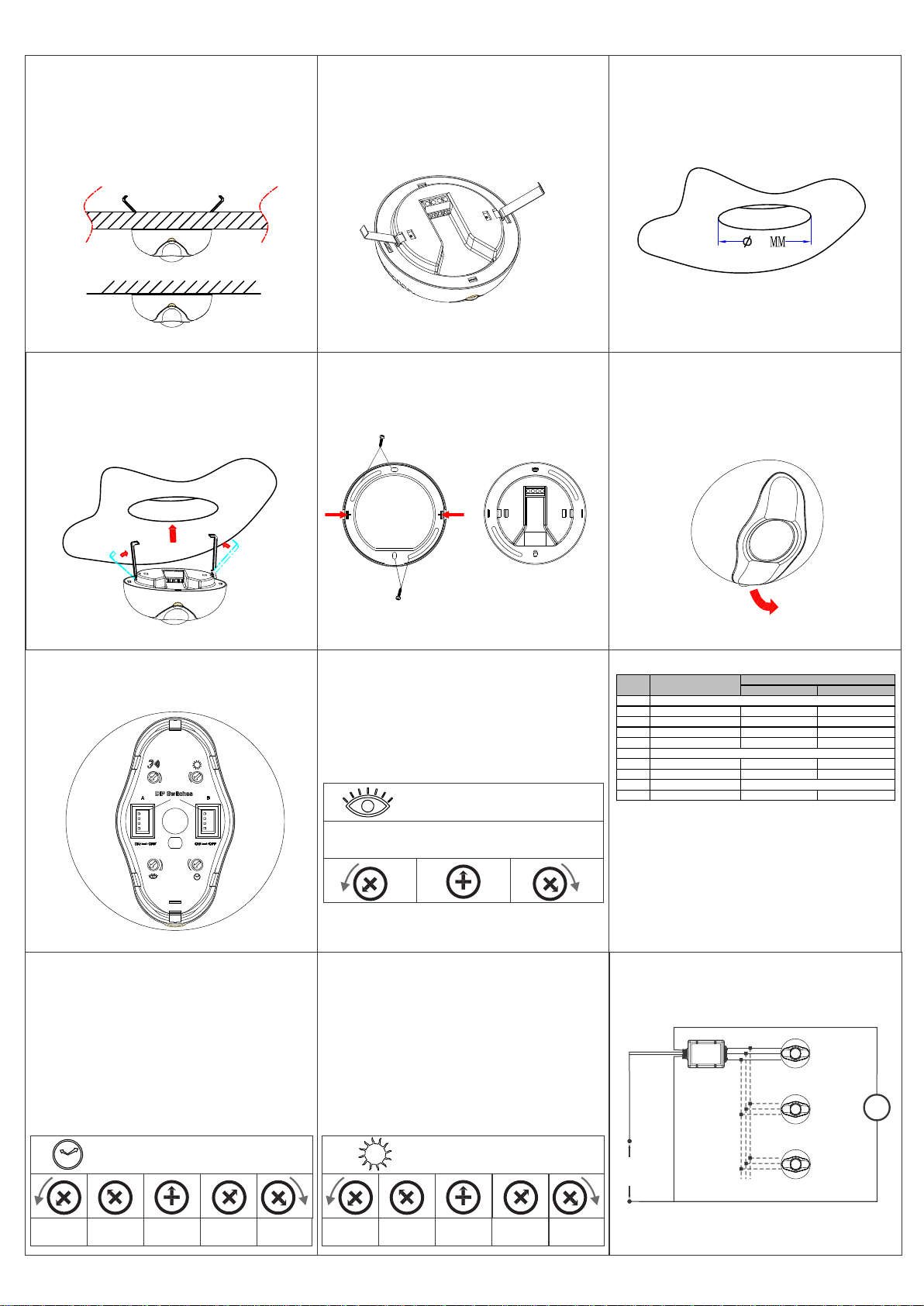
Drop-Ceiling Mounting: Base Preparation
Install the two retaining springs as shown.
Drop-Ceiling Mounting: Panel Preparation
Use a hole saw to cut a 85 mm circular hole in the
drop-ceiling panel at the desired location.
Drop-Ceiling Mounting: Sensor Installation
Press the retaining springs together, then push
the springs and the sensor base through the hole
until the sensor rim is seated against the panel.
Sensor Opening
Slide a fingertip under the tab at one end of the
cover. Pull gently to remove the cover.
Solid-Ceiling Mounting
Use the three screws (supplied with the sensor)
to fasten the base ring to the ceiling. Align the
sensor's two eyelets with the base ring's two
hooks. Press the sensor onto the base ring.
Sensor Mounting Choices
The sensor may be mounted either in a drop-
ceiling panel, or on a solid ceiling. In a drop-
ceiling panel, two metal springs serve to retain
the sensor in the panel. On a solid ceiling, the
sensor is mounted on a base ring (supplied with
the sensor).The base ring is fastened to the
ceiling by means of three screws.
5
8
Delayed-Off Time Adjustment
The sensor turns light off if motion is not detected
within the Delayed-Off Time interval. For less
disruption, adjust clockwise (CW). For better
energy savings, adjust counter-clockwise (CCW).
Sets the infrared range
Range setting
Full CCW = min.
Full CW = max.
Operation Control Console
All aspects of sensor operation can be adjusted
here.
Ambient Light
20Lux 40Lux 80Lux 160Lux 320Lux
Delayed-Off Time
30sec 5min 10min 20min 30min
2
11
Sunset Sensor Adjustment
The sunset sensor saves energy by not switching
the light on when there is sufficient daylight in the
room. It can be enabled or disabled by the dip
switch B1. When the sunset sensor is enabled, the
sensor goes into stand-by mode when the natural
light level exceeds the selected Lux level
inhibiting the light from turning on. To set the Lux
level, draw curtains or shades until the room is at
the darkness that light should be turned on. Adjust
the Lux level from low to high until lighting is
activated. Note that the sunset sensor is disabled
when the occupancy sensor is in test mode.
Infrared Adjustment
For maximum range and sensitivity, set fully
clockwise (CW). If reduced range and sensitivity
are required, then turn counter-clockwise (CCW)
and test.
Dip Switch Settings
Off On
A1 Not Used
A2 Not Used
A3 Not Used
A4 Walk-Thru/Normal Walk-Thru Enabled Normal Occupancy
B1 Sunset Sensor Enabled Disabled
B2 LED Indicator Enabled Disabled
B3 Test Mode
B4 Not Used
Off-On-Off / On-Off
Bank A
Bank B
Dip
Switch Function
Settings
Wiring Diagram:
Sensor 1
Sensor 2
....
Sensor N
Power
Pack
Note: more than one sensor can be connected
to a power pack.
Light
Live
Neutral
+
+
+
Line
85 - 277 V AC
50/60Hz
Load
-
-
-
Control
Control
Control
Other Sure Electronics Accessories manuals


