Important:
• After changing the factory setup (output signal and/or output scale) the original type number on the EE820 identification label loses
its validity; it does not match any longer the device setup.
• The return to factory setup function of EE-PCS restores the original adjustment/calibration of the device, but does not affect the user
setup for output signal and output scale.
DIGITAL VERSION
HARDWARE
The bus termination shall be realized with 120 Ohm resistor (slide switch on the board).
Very important:
For proper function the power supply must be strong enough to ensure supply voltage within the specified range (see technical data) at
any time and at all devices in the bus. This is particularly relevant when using long and thin cables which can cause high voltage drop.
Please note that a single EE820 requires peak current of 150 mA.
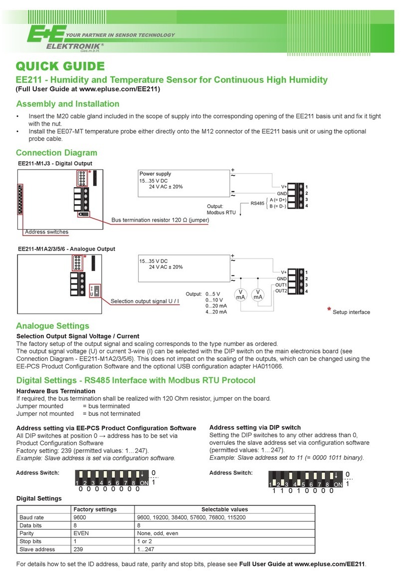
ADDRESS SWITCH
1
Address setting via EE-PCS Product Configuration Software:
All Dip-Switches at position 0 → address has to be set via Product Configuration Software
Modbus (Slave device): factory setting EE820: 67 (permitted values: 1…247).
BACnet (Master device): factory setting EE820: 67 (permitted values: 0…127).
Example: Slave address is set via configuration software.
ADDRESS SWITCH
1
Address setting via Dip-Switch:
Modbus (Slave device): Setting the Dip-Switch to any other address than 0, overrules the slave
address set via configuration software (permitted values: 1…247).
BACnet (Master device): Setting the Dip-Switch to any other address than 0, overrules the slave
address set via configuration software.
BACnet Note: permitted values are 0…127. The 8th bit of the Dip-Switch is ignored
(ID 127 = 0111 111).
To set address 0 via Dip-Switch, the 8th bit shall be set to 1 (ID 0 = 1000 0000).
Example: Slave address set to 11 (= 0000 1011 binary).
BACNET SETUP
Please see PICS (Product Implementation Conformance Statement) - available on www.epluse.com/EE820.
MODBUS SETUP
The measured values are saved as a 32 bit float value and 16 bit signed integer.
The EE820 factory setting for the slave-ID (Modbus address) is 67 as an integer 16 bit value.
This ID can be changed by the user in the register 60001 (0x00), permitted values are 1…247.
The serial number as ASCII-code is located at read register address 30001-30008 (16 bit per address).
The firmware version is located at register address 30009 (bit 15...8 = major release; bit 7...0 = minor release).
FLOAT (read register):
Function code /
Register number1) [Dec]
Register
address2) [HEX]
Parameter
name
31061 0x424 CO2average [ppm]
31063 0x426 CO2RAW [ppm]
1) Register number starts from 1 2) Register address starts from 0
INTEGER (read register):
Function code /
Register number1) [Dec]
Register
address2) [HEX]
Parameter
name
34031 0xFBE CO2average [ppm] * 1
34032 0xFBF CO2RAW [ppm] * 1
*1 is the scale 1:1 (e.g.: 800 is equivalent to 800 ppm)
INFO (read register):
Function code /
Register number1) [Dec]
Register
address2) [HEX]
Parameter
name
30001 0x00 Serial number (as ASCII)
30009 0x08 Firmware version
INTEGER (write register):
Function code /
Register number1) [Dec]
Register
address2) [HEX]
Parameter
name
60001 0x00 Slave-ID (modbus address)*
60002 0x01 Modbus protocol settings**
* If the ID is set via DIP-Switch the response will be NAK.
** For Modbus protocol setting please see Application Note Modbus AN0103 at www.epluse.com
MODBUS RTU EXAMPLE
Example of MODBUS RTU command for reading the CO2(float value) CO2= 1288,34375 ppm from the register 0x424
Device EE820; slave ID 67 [43 in HEX]
Reference document, chapter 6.3: http://www.modbus.org/docs/Modbus_Application_Protocol_V1_1b.pdf


