Seneca MyBoat User manual

1
USER MANUAL MI004913-E
User Manual

USER MANUAL MI004913-E
ACTIVATION CODE

USER MANUAL MI004913-E
TABLE OF CONTENTS
1 - INTRODUCTION:
-Content of the pack p.2
-Logical diagram of the MyBoat system p.3
-Product description p.4
-MyBoat control unit p.5
-Monitoring sensors p.6
-Sensor representation in the Home screen p.7
2 - INSTALLATION
-Installation of the MyBoat control unit p.8
-Replacing the sensor battery p.9
-Sensor installation p.10
3 - ACTIVATION
-Cloud account registration and MyBoat service activation p.16
-Product activation p.17
4 - MYBOAT MOBILE APP
-HOME screen p.20
-STATUS screen p.21
-HISTORY screen p.22
-SETTINGS menu p.23
5 - ADVANCED SETTINGS
-Procedure to replace a sensor p.30
-AdvancedcongurationoftheMyBoatcontrolunit p.31

02
USER MANUAL MI004913-E
1 - INTRODUCTION: CONTENT OF THE PACK
1 - INTRODUCTION: LOGICAL DIAGRAM OF THE MYBOAT SYSTEM
1
2
3
1 - MyBoat control unit
5 - Power cable with cigarette lighter plug
2 - Sensors (the image refers to a kit with 8 sensors)
6 - Batteries for each sensor (included and already installed)
4 - SIM card (optional, see leaet)3 - User Manual
7 - Control unit xing support 8 - Self-tapping screws for wall xing (x2)
22
2 2 2
2
52

03
USER MANUAL MI004913-E
1 - INTRODUCTION: CONTENT OF THE PACK
1 - INTRODUCTION: LOGICAL DIAGRAM OF THE MYBOAT SYSTEM
S1 S2 S3 S4 S5 S6 S7 S8
DIN1 DIN2 DIN3 DIN4
From 2 to 8 sensors (*)
Digital inputs
Relay digital outputs
Power supply
AUX 1 AIN 2
AUX 2
Analogue inputs
4 - SIM card (optional, see leaet)
(*) According to the KIT purchased, check the information on the side of the pack

04
USER MANUAL MI004913-E
1 - INTRODUCTION: PRODUCT DESCRIPTION
MyBoatisaexiblecontrolsystemconsistingofasmartcontrolunitandwirelessmonitoringsensorsforthe
remotecontrolandalarmmanagementinrealtimeofyachts,boatsingeneralandeet.Thesystemisbasedon
aCloudplatformoeredbySenecas.r.l.(https://cloud.seneca.it).Thepriceoftheproductincludesthesubscrip-
tiontotheMyBoatserviceforthersttwoyearsfromproductactivation.Forinformationandrenewalcostsofthe
service, go to
www.seneca.it/MyBoat
.
MyBoatisaserviceoeringmanyfunctionsusefultomonitoryourboatthroughimmediateconsultationandthe
practicaluseofbothbrowserandmobileapp.UsingtheMyBoatapp,availableintheAppleandAndroidstores,
youcancheckyourboatwhilemoving,verifythestateofthesensorsandbewarnedinrealtimeincaseofan
alarm(pushnotications,SMSoremail).
AswellasmanagingthecommunicationwiththesensorsandtheSENECAcloudplatform,thecontrolunitisset
fortheadvancedcongurationandoptionalremotecontrolof4digitalinputs,1timedrelayoutput(e.g.siren),1
non-timedrelayoutput(auxiliary),1analogueinputforservicebatterysensor(alreadywiredtothecontrolunit
powersupply)and1fuellevelanalogueinput.Fordetailsontheadvancedconguration,refertochapter5.
SENECA makes available various types of kits consisting of various sensors to monitor: the boat access points, the
state of the engine compartment, the state of the service, engine and general batteries, the current position of the
boat,thewaterlevelinthebilgesandthetemperaturebothinthecabinandinthebilge.
1 - INTRODUCTION: MYBOAT CONTROL UNIT
MyBoat 11-6
MyBoat 13-8
DOCK
BILGE1 BILGE2
The images and diagrams shown must be considered as indicative and not binding.
SERVICES
ENGINES ENGINES ENGINES HATCH 1 HATCH 2

05
USER MANUAL MI004913-E
1 - INTRODUCTION: PRODUCT DESCRIPTION
MyBoat control unit
The MyBoat control unit is a product
derived from SENECA MyAlarm3. Remote
alarm, telemetry and datalogging industrial
unit.
Technical characteristics:
• DisplayLCD128x32Dots
• RechargeableLi-Iobuerbattery,upto
8 hours’ autonomy
• ReplaceableGSM/GPRS/GPSantenna
on SMA connector
• SlotforminiSIM(15x25mm)
• GPSinternalmodulewithbuilt-inan-
tenna(externalA-GPSantennaavaila-
ble as an option)
• ON/OFFkeyanddisplayscrollkey
• StatusLED:devicepower/status,GSM/
GPRS status
• SlotformicroSDcard(foranyrm-
wareupdateanddeviceconguration
toaccessthe2Gnetworkthrougha
SIMsuppliedbythebestknownpro-
viders)
• USB micro port (reserved)
Advanced technical characteristics:
• 4 digital inputs to control electrical
devices
• 1 analogue input for supply voltage
reading
• 1 analogue input for fuel check
• 1 timed relay digital output (e.g. siren
or bilge pump)
• 1 non-timed relay output
Power supply for cigarette lighter plug
1 - INTRODUCTION: MYBOAT CONTROL UNIT
MyBoat control unit
Assembly detail onto DIN rail
forwalltting.Forcorrect
installation,followinstructions
on page 06.

06
USER MANUAL MI004913-E
Thesensorsarewirelessradiode-
viceswithIP20casethatcommuni-
catewiththeMyBoat
control unit using 868 Mhz radio
frequency.Theyarettedwith3V
CR2 batteries guaranteeing their
operation for about 1 year (*). With
the MyBoat app, you can monitor
the state of the batteries of the
individual sensors, to foresee their
replacement.
The sensors integrate the anti-tam-
pering function and can be 3 types:
• magnetic for access control
• level for bilge control
• with“faston”connectorsand
fuse to control the battery volt-
age.
Frontviewofamagneticsensor Bilgewaterleveldetector
Access control sensor magnet
1 - INTRODUCTION: MONITORING SENSORS
Type S sensors:
1 - INTRODUCTION: SENSOR REPRESENTATION IN THE HOME SCREEN
(*) Estimated life under normal operating conditions
BackviewwithIDlabel
Frontviewofalevelsensor
Engine battery status and charge and generator
battery detector Access control sensor type 2 magnet

07
USER MANUAL MI004913-E
1 - INTRODUCTION: MONITORING SENSORS
1 - INTRODUCTION: SENSOR REPRESENTATION IN THE HOME SCREEN
Main screen
Boat access control
Engine access control
Bilge 1 control
Generator battery control
Engine battery control
S1
S2
S3
S4
S5
S6
S7
S8
Bilge 2 control
Hatch 1 control
Hatch 2 control
ENABLED DISABLED ALARM
S1
S2
S3
S4
S5
S6
S7 S8
C1
C1
Monitoring the status of the service
battery takes place via the MyBoat
controlunitanditspowersupply
connector. With this it is possible to
detect the status and voltage of the
service battery it is connected to.
ICON COLOUR KEY
N.B.:
Thewarningaboutcabinaccessoren-
ginecompartmentopeningisalwaysin
real time.
Temperature detection takes place every
15 minutes. In case of variation in sta-
tus, the alarm is given in real time.
Battery voltage detection takes place
every 15 minutes. In case of variation in
status, the alarm is given in real time.
Thebilgewaterlevelsensorsignalsthe
alarminrealtime.Ifthereisnowaterin
the bilge, the alarm is deactivated after
15 minutes.
Ifasensordoesnotcommunicatewith
the control unit for over 100 minutes, all
thealarmsoftheinvolvedsensorwillbe
activated.

08
USER MANUAL MI004913-E
2 - INSTALLATION: INSTALLATION OF THE MYBOAT CONTROL UNIT
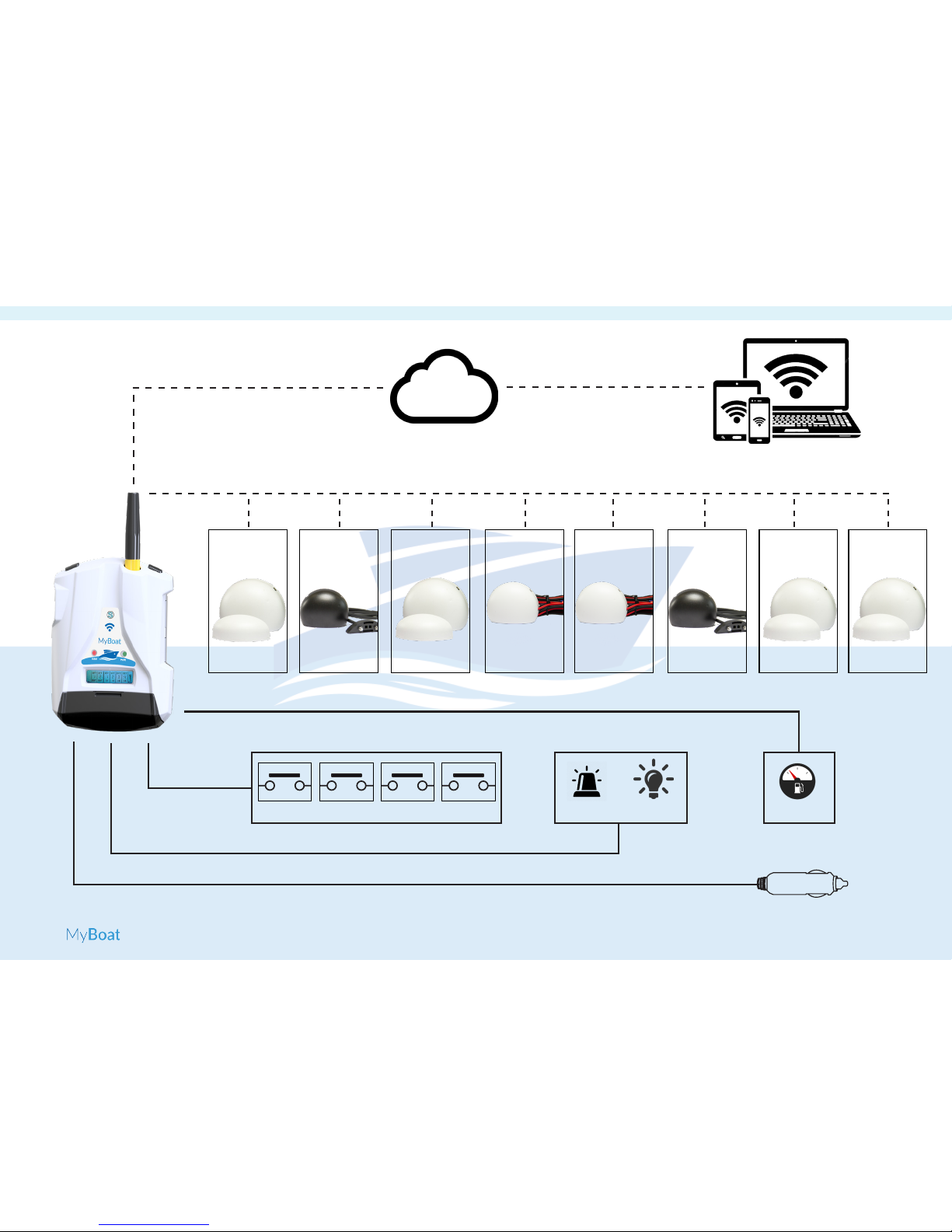
For optimum reception of the GPS
signal given by satellites, it is better
to place the MyBoat horizontally on
a surface in an area not covered
by metal structures. If this is not
possible,anoptionalexternalanten-
nawith3mcable(codeA-GPS)is
available.
2 - INSTALLATION: REPLACING THE SENSOR BATTERY
Figure 2
Theupdateofthecontrolunitrm-
wareispossibleviathemicroSD
cardsupplied.Followthefollowing
procedure:
1. CopytheleFW.BINinthemain
folder of the micro SD card;
2. Switchthecontroluniton(***).
3. Insert the micro SD card into
the MyBoat control unit;
4. Waitforthemessageconrming
theupdateofthermware;
5. Press“OK”andwaitforinstal-
lationtocompletewiththeunit
restarting;
6. Thecontrolunitwritesthenew
rmwareontheashmemory
during this phase.
N.B. In order to guarantee the
MyBoatcontrolunitworkscorrect-
ly, THE CONTENT OF THE SD CARD
MUST NOT BE REMOVED.
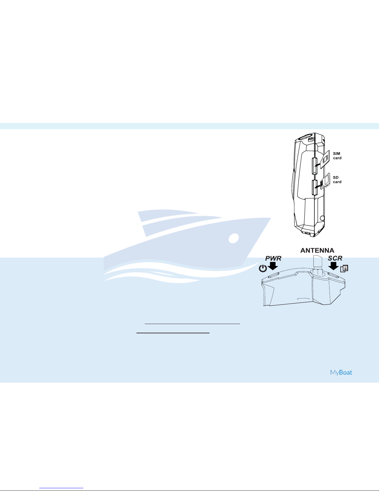
MyBoatisttedwithanON/OFF
PWR key positioned in the LH top
corner (Figure 3).
Figure 3
N.B.:
First startup procedure:
FW update procedure:
Switchingonandscrollkeys:
1. Insert the mini SIM card into the
switched-oMyBoatcontrolunit
(*);
2. InserttheSDcard(seegure2);
3. ConnecttheGSM/GPRSantenna
(**);
4. Connectthepowersupplyto
theterminalblockfollowingthe
instructions on page 29;
5. Insert the cigarette lighter plug
toswitchtheMyBoatcontrol
unit on.
Toconrmtherststartupprocedure
is correct, the GSM LED will start
ashing3timesasecond.
(**)ConnectanyA-GPSoptionalantennafollowingthe
proceduresuppliedwiththeantenna.
(*) Ensure you have removed the locking PIN during
theswitch-on phase using another device, and at the
sametimecheckdataconnectionisworkingproperly.
(***)Ensurethecontrolunitispoweredviatheciga-
rette lighter cable supplied.
Toswitchito,keepthePWRkey
pressedforafewseconds.
ThedeviceisttedwithaSCRkey,
in the RH top corner. Pressing this
key displays the parameters.

09
USER MANUAL MI004913-E
2 - INSTALLATION: INSTALLATION OF THE MYBOAT CONTROL UNIT
screw2
screw1
All sensors are factory-set and sup-
pliedwithabattery.
To replace the batteries in the
sensors,followthefollowinginstruc-
tions:
• Withacrossheadscrewdriv-
er,removethetwofastening
screwsfromthedomeasshown
in Figure 1;
• Open the dome paying attention
to the orientation as in Figure 2;
• Insertthebatterysuppliedwith
thepositivepoleasshownin
Figures 3 and 4;
• Close the sensor dome again
andfastenthescrews.
Figure 1 Figure 3
Figure 2 Figure 4
2 - INSTALLATION: REPLACING THE SENSOR BATTERY

10
USER MANUAL MI004913-E
2 - INSTALLATION: SENSOR INSTALLATION
S1 Boat access control
1. Remove the protection tab to
powerthesensor;
2. Identify the installation point of
both the sensor (e.g. door frame,
lintel) and the magnet (assess
whethertouseatype1ortype
2 magnet, according to require-
ments) and clean the 2 areas
identied;
3. Apply the round velcro patch onto
the magnet;
4. Check it is positioned correctly
and,toguaranteeitworksprop-
erly,leaveamaximumdistance
of10mmbetweenthetwoele-
ments;
5. Removethevelcroprotectionlm
from both the sensor and the
magnet,applyinthetwoareas
identied,pressinglightlyfora
fewseconds.
alarm disabled alarm enabled
22° Closed door
Open door Sensor S2Type 1 magnet
Sensor S2Type 2 magnet
N.B. If it is not possible to position
themagnetandsensoronaxis,use
thetype2magnetasshowninthe
gure.

11
USER MANUAL MI004913-E
alarm disabled alarm enabled
S2 and S6 Bilge 1 and 2 control
Figure 1 Empty bilge
Figure 2 Full bilge
cable supplied
cable in black sheath level
contact
sensor
2 - INSTALLATION: SENSOR INSTALLATION
1. Remove the protection tab to
powerthesensor;
2. Identify the installation points
of the sensor and level contact,
pulling the cable supplied (as
inFigure1)andcleanthetwo
areasidentied;
3. Remove the velcro protection
lmfromboththesensorand
thecontactandapplyinthetwo
areasidentied,pressinglightly
forafewseconds.
2 - INSTALLATION: SENSOR INSTALLATION
N.B.: Ensure that, once applied,
the level contact does NOT touch
thewaterinthebilge;

12
USER MANUAL MI004913-E
2 - INSTALLATION: SENSOR INSTALLATION
S3 Engine access control
alarm disabled alarm enabled
Engine compartment
open
Engine compartment
closed
Installation detail
Sensor S2 Type 1 magnet
2 - INSTALLATION: SENSOR INSTALLATION
1. Remove the protection tab to
powerthesensor;
2. Identify the installation point of
both the sensor (e.g. door frame,
lintel) and the magnet (assess
whethertouseatype1ortype
2 magnet, according to require-
ments) and clean the 2 areas
identied;
3. Apply the round velcro patch onto
the magnet;
4. Check it is positioned correctly
and,toguaranteeitworksprop-
erly,leaveamaximumdistance
of10mmbetweenthetwoele-
ments;
5. Removethevelcroprotectionlm
from both the sensor and the
magnet,applyinthetwoareas
identied,pressinglightlyfora
fewseconds.
Sensor S2Type 2 magnet
N.B. If it is not possible to position the
magnet and sensor on axis, use the
type2magnetasshowninthegure.

13
USER MANUAL MI004913-E
alarm disabled alarm enabled
S4 and S5 Engine and service battery control
+-
Battery
8mm fork
Fuse holder
S4/S5sensor
2 - INSTALLATION: SENSOR INSTALLATION
1. Remove the protection tab to
powerthesensor;
2. Identify the installation point
of the sensor according to the
length of the cable to connect to
the battery and clean the area
identied;
3. Remove the velcro protection
lmfromthesensor.Applytothe
areaidentiedpressinglightlyfor
afewseconds;
4. Connectthecablewiththe8mm
forks to the battery terminals,
paying attention to polarity as
showninthesidegure.
2 - INSTALLATION: SENSOR INSTALLATION
12.8 V
12.8 V
0.0 V12.8 V

14
USER MANUAL MI004913-E
Open hatch
alarm disabled alarm enabled
S7 and S8 Hatch 1 and 2 control
OPEN
Closed hatch
SensorS7/S8 Magnet
2 - INSTALLATION: SENSOR INSTALLATION
1. Remove the protection tab to
powerthesensor;
2. Identify the installation point of
both the sensor (e.g. door frame,
lintel) and the magnet (assess
whethertouseatype1ortype
2 magnet, according to require-
ments) and clean the 2 areas
identied;
3. Apply the round velcro patch onto
the magnet;
4. Check it is positioned correctly
and,toguaranteeitworksprop-
erly,leaveamaximumdistance
of10mmbetweenthetwoele-
ments;
5. Removethevelcroprotectionlm
from both the sensor and the
magnet,applyinthetwoareas
identied,pressinglightlyfora
fewseconds.
Installation detail
Sensor S2Magnet 2
If it is not possible to position the
magnet and sensor on axis, use the
type2magnetasshowninthegure.

15
USER MANUAL MI004913-E
2 - INSTALLATION: SENSOR INSTALLATION

16
USER MANUAL MI004913-E
3 - ACTIVATION: CLOUD ACCOUNT REGISTRATION AND MYBOAT SERVICE ACTIVATION
To use the MyBoat monitoring
system you need to create a SENE-
CA Cloud account and activate the
MyBoat service.
The MyBoat KIT includes the cost
of the usage fee for a period of 24
monthsfromthedateofrstacti-
vation.
Formoreinformationandrenewal
costs visit the site:
www.seneca.it/en/myboat
The activation procedure is available
fromboththeHTML5webbrowser
and the MyBoat mobile app.
Activation by WEB browser
• Insert the SIM (*) and turn on
the MyBoat control unit;
• Go to https://cloud.seneca.it
to register your SENECA Cloud
account (if not previously regi-
stered for other services);
• After activating your account
andloggingin,selectthe“Cloud
Services”buttonandclickon
the“ADD”buttonatthetop
right;
• Enterthe“ActivationCode”of
5+10 characters available on
the back cover of this manual
(**)andselectthe“ADD”but-
ton again;
• Theserviceisnowactiveandit
is possible to access the status
of the MyBoat system from both
thewebbrowserandtheMyBo-
at mobile app.
Toviewthestatusoftheboatfrom
awebbrowser:
• access the SENECA Cloud at
https://cloud.seneca.it
• select“CloudServices”.
• select“OPEN”closetothecrea-
ted service
The same functions as the mobile
app are available.
Activation by MyBoat mobile App
• Insert the SIM (*) and turn on
the MyBoat control unit
• Install the MyBoat app available
in the iOS and Android stores
usingthefollowingQRcodes:
• Registerandloginfortherst
time;
• Once you have logged in the
MYBoatappwillaskfortheacti-
vation code
• Enterthe“activationcode”of
5+10 characters available on
the back cover of this manual
(**);
• Nowtheserviceisactiveandit
is possible to access the sta-
tus of the MyBoat system both
fromawebbrowserandfroma
mobile app.
Toviewthestatusoftheboatfrom
the mobile app: launch the app and
loginwithyourCloudcredentials.
Thecredentialswillbesavedfor
later logins.
Add more users to the service
AddingnewuserstotheMyBoat
service is a task that can only be
performedbyawebbrowser.Itis
possibletodenemulti-levelusers
withdierentauthorizationsdepen-
dingonthetypeofuser(owner,
maintainer, guest):
• ADMIN: displays information,
sends commands, changes
MyBoat

17
USER MANUAL MI004913-E
3 - ACTIVATION: CLOUD ACCOUNT REGISTRATION AND MYBOAT SERVICE ACTIVATION
Fleet management
Through the Cloud platform console
you can manage multiple MyBoat
servicesassociatedwithonecloud
account (one account for kind of
boats).
1. After logging in https://cloud.
seneca.it,selectthe“Cloud
Services”buttonandselectthe
“ADD”buttonatthetopright;
2. Enterthe“Activationcode”of
5+10 characters on the back
cover of the manual associated
withtheKITyouwanttoadd
(**)andselectthe“ADD”but-
ton again;
3. Fromnowontheserviceisacti-
ve and it is possible to access
the status of the MyBoat system
bothfromthewebbrowserand
from the MyBoat mobile app of
the same name.
Restore to factory defaults:
To return your MyBoat monitoring
systemtofactorysettings,follow
these instructions:
• Access your cloud account ht-
tps://cloud.seneca.it via your
webbrowser
(*)nelcasoincuisiutilizziunaSIMdierente
da quella fornita nel KIT, assicurarsi di aver
rimosso il PIN di blocco nella fase di accensio-
ne tramite altro dispositivo.
(**) l’operazione richiede meno di 1 minuto
durante il quale avviene la sincronizzazione del
dispositivo con la piattaforma Cloud.
settings
• EDITOR: displays information,
sends commands
• USER: displays information
• NONE: none
Howto:
• Accessing your Cloud account
fromawebbrowserhttps://
cloud.seneca.it
• Select“Users”.
• Select“ADD”
• Set the user information and
select SAVE to create the user
After creating the credentials you
canwaitfortheusertoconrmhis
data or:
• Selectthe“MANAGEMENT”but-
ton (user related)
• Select the ADVANCED menu
• Select“ActivateUsermanually”
• Select the ADVANCED menu
again
• Select“ManagePermissions”.
• Itwillbesucienttoassignto
thenewusertheroletypefor
each Service by selecting the
relevant button.
To add more users repeat the ope-
ration.
• Select“CloudServices”
• Selectthe“MANAGEMENT”
buttonfortheServiceyouwish
to reset.
• Selectfromthe“ADVANCED”
menu the item Remove Service
“servicename”.
• Proceedingwiththeremovalof
theservice,allsettings/infor-
mationrelatedtoitwillbereset
irreversibly.TheServicewill
nolongerbeassociatedwiththe
account and the activation code
can be used again on another
cloud account.
TheMyBoatserviceisnowbackto
factory default.

18
USER MANUAL MI004913-E
3-ACTIVATION: CONNECTION INSTRUCTIONS OF THE DEVICE TO CLOUD SENECA
SWITCH ON
POWER UNIT GSM SEARCH CONNECTED
TO GSM
CONNECTED
TO CLOUD SHUTDOWN
STATUS REPORTS MEANING DURATION
GSM SEARCH
GSM LED Yellow ashing
Fast and no GSM signal
indication on the display
The control unit is sear-
ching to the GSM network A few seconds
CONNECTED TO GSM
GSM LED Yellow slow
ashing.
Appearance of notches with
GSM signal on the display
The control unit is correctly
connected to the GSM
network
A few seconds
CONNECTED TO CLOUD
GSM LED Yellow ashing
Fast and presence of GSM
signal notches on display
The control unit is correctly
connected to the GPRS
network and the Seneca
cloud
Until the control unit is
turned off
3-CTIVATION: TROUBLESHOOTING
Other manuals for MyBoat
2
Table of contents
Popular Boating Equipment manuals by other brands

DockStar
DockStar Smart Thruster installation guide

Sea-doo
Sea-doo GTX DI 5659 Operator's guide

bamar
bamar RLG EVO Series instruction manual

Vetus
Vetus RimDrive RD125 installation instructions

Ronstan
Ronstan RF6 instruction manual

Old Town Canoe Co.
Old Town Canoe Co. 01.1332.2406 installation instructions