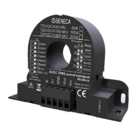
Seneca T201DC100 User manual

MI00353-2-EN ENGLISH 1/5
This document is property of SENECA srl. Duplication and reprodution are forbidden, if not authorized. Contents of
the present documentation refers to products and technologies described in it. All technical data contained in the
document may be modified without prior notice Content of this documentation is subject to periodical revision.
INSTALLATION AND USER’S GUIDE
Language manual
English
Product
T201DC100
Description
Passive transducer of direct current
100 Adc, for 4 – 20 mA current loop
Series of product
T
Contents:
1.0 Disclaimer
2.0 Description and
general specifications
2.1 Description
2.2 General specification
3.0 Technical specification
3.1 Input
3.2 Output and supply
3.3 Accuracy
3.4 Environmental condition
3.5 Connector
3.6 Box
3.7 Reference standards
3.8 Dimensions
4.0 Preliminary use instructions
5.0 Electrical connections
5.1 Output current for loop 4 ..20 mA
5.2 Current input.
5.3 Connection to the DIN rail
6.0 DIP-SWITCH settings
Pag.
4
4
2
2
2
6
Manufacturer
SENECA s.r.l.
Via Austria, 26 – 35127 – PADOVA – ITALY
Tel.+39.049.8705355 - 8705359 - Fax +39.049.8706287
Web
Manuals and configuration software are available at www.seneca.it
Mail

MI00353-2-EN ENGLISH 2/5
1.0 DISCLAIMER
Before execution any operation it is advised to read all the content of this
manual. Only electrical-skilled technicians can use the module described in this
installation manual. It’s installer's responsibility to assure that the installation is
in compliance to the security standards regulated from the law.
Only the Manufacturer is authorized to repair the module or to replace
damaged components.
The warranty is void in case of errors resulting from improper use,
modifications or repairs carried out by Manufacturer-unauthorised personnel
on the module.
3.0 TECHNICAL SPECIFICATIONS
3.1 Input
Connection
Passing wire
Hole diameter
21 mm; 0,8 Inch
2.0 DESCRIPTION AND GENERAL SPECIFICATIONS
2.1 Description
The T201DC100 is an isolated and passive, contact-less loop powered direct current
transducer. The T201DC100 has functions and look very similar to a standard current
transformer, but it is enabled to measuring the continuous current component that flowing
through it. For its electrical endurance, ease of use and compact dimensions, the
T201DC100 fits every kind of current measurement up to 100 Adc.
2.2 General specifications
- Suitable for solar panels, batteries, battery charger,power units and generic DC load.
- No shunt, no power consumption from the measure circuit
- High accuracy rating: class |0.2|
- Loop-powered 4 – 20 mA, 6 to 28 V, protected from reverse polarity and
transient up to 120 V, surge up to 1.5 J.
- Eight scales unipolar or bipolar selectable via dip switches
- Damping filter available to improve the stability of reading
- Reading of current pulsed or alternating currents with superimposed components
- Built-in microprocessor system fault check
- Over-temperature protection
- "single wire" possible wiring by powering with the device from the measuring current itself
and closing to the system common return.
- Possibility of mounting on the DIN rail through the support provided in the sales package.
SENECA s.r.l.
Via Austria, 26 – 35127 – PADOVA – ITALY
Tel. +39.049.8705355 - 8705359 - Fax +39.049.8706287
Manuals and configuration software are available at www.seneca.it

MI00353-2-EN ENGLISH 3/5
3.2 Output and power supply
Type
Passive current loop 4 – 20 mA
Terminals
Removable screw terminal pitch 5 mm for max 2.5mm² cables
Limits
Internal fault / Over-temperature: 3,5 mA
Under-range / Over renge: 3,6 / 21,0 mA
Correct measure: 3,8 / 20,5 mA
Min. - Max. loop voltage
6 V - 28 V
Other protections
Polarity reversal
Loop current limiting on hardware fault
Over-temperature protection
Range
- Unipolar 0 – 10 A, Bipolar -10 – 0 – +10 A
- Unipolar 0 – 25 A, Bipolar -25 – 0 – +25 A
- Unipolar 0 – 50 A, Bipolar -10 – 0 – +50 A
- Unipolar 0 – 100 A, Bipolare -25 – 0 – +100 A
AC superimposed (f 35
Hz)
- Allowable peak value: -30 – +120 A
- Full-wave rectified: -20 – 80 A
- Half-wave rectified: -10 – 40 A
Over-voltage category
Bare conductor
CAT. III 300V
Insulated conductor
CAT. III 600V
3.4 Environmental condition
Index protection
IP20
Operating temperature
-20 °C – +70 °C
Humidity
10 – 90% a 40 °C non-condensing
Storage temperature
- 40 – +85°C
3.3 Accuracy
Maximum errors
- Input section: 0,1 % + 14 mA
- Output section: 0.05 % + 4 µA
TempCo
< 150 ppm/K
Error due to EMI
< 50 µA, test on bare wire Ø 10 mm
Response time
- Without damping filter: 100 ms
- With damping filter: 600 ms
3.5 Connections
Connections
Removable screw terminal pitch 5 mm for loop 4 – 20 mA
Tightening torque 7.0 Lb•inch = 0.8 N•m
21 mm through hole for wire
3.6 Box
Dimension
97 x 68 x 26 mm without screw terminals
Box
PA6, Black color

MI00353-2-EN ENGLISH 4/5
3.8 Dimensions
5.0 ELECTRICAL CONNECTIONS
Remove power supply before wiring.
5.1 Output current loop 4 – 20 mA
A maximum voltage supply of 28 V
can be connected directly to the loop
4 – 20 mA of the T201DC100.
3.7 Standards
Standards
EN61000-6-4 (electromagnetic emission, industry).
EN64000-6-2 (electromagnetic immunity, industry).
EN61010-1 (safety).
Notes:
- Use with copper conductor.
- Use in Pollution Degree 2 Environment
- Power Supply must be Class 2
4.0 PRELIMINARY INSTRUCTION FOR USE
The T201DC100 can be installed in any position and place in accordance to expected
environmental conditions. Use the included holder bracket when fixing to a DIN rail.
High-strength static magnetic fields may change the output value: keep away from
permanent magnets, electromagnets or iron bulks that cause such a modification
of the surrounding magnetic field; try a different orientation if zero error was greater
than expected.
+
-
U = 28 V
max
U
I
mA
N.C.
N.C.
+
97 mm
26 mm
68 mm
36.7 mm
21 mm

MI00353-2-EN ENGLISH 5/5
5.2 Connection for reading input current
To measure the current flowing through the cable,
plug the cable into the center hole of T201DC100
(as shown in the figure).
The maximum current that can be measured using
T201DC100 is 100A.
To increase the sensitivity of current measurement,
insert the wire several times through the center
hole T201DC100, creating a series of turns. The
sensitivity of current measurement is proportional
to the number of turns. Example:
Choose the end scale and wrap the wire 5 times
around the center hole obtaining 4 turns. The initial
end scale will be result 5 times smaller: the
measure proves to be more sensitive
Place the coils with symmetry in order to maintain
the sensitivity of the device.
The current direction is
shown in the figure above.
5.3 Installation on DIN rail
DIN rail Two accessories provided for DIN rail mounting
Disposal of Electrical & Electronic Equipment (Applicable throughout the European Union and other European
countries with separate collections programs). This symbol, found on your producr or on its packaging, indicates that
this product should not be treated as household waste when you wish to dispose of it. Instead, it should be handed
over to an authorised collection point for the recycling of electrical & electronic equipment. By ensuring this product
is didposed of correctly, you will help prevent potential negative consequences to the environment and human
health, which could otherwise be caused by inappropriate disposal of this product. The recycling of materials will
help to conserve natural resources. For more detailed information about the recycling of the product, please contact
your local city office, waste disposal service of the retail store where you purchased this product.
6.0 DIP-SWITCH SETTINGS
Set the dip-swich to choose the unipolar or bipolar scale and to enable or disable the filter.
Bipolar scales
1
2
3
4
Scale
-10–10
A
-25–25
A
-10–50
A
-25–100
A
Unipolar scales
1
2
3
4
Scale
0–10
A
0–25
A
0–50
A
0–100
A
Filter
1
2
3
4
Filter
Disable
Enable
KEY
ON
Table of contents
Other Seneca Transducer manuals
Popular Transducer manuals by other brands

Mindray
Mindray P8-2TU Operator's manual

Balluff
Balluff BTL5-T1 Series manual

halstrup-walcher
halstrup-walcher P82R instruction manual

Emerson
Emerson Fisher 546NS instruction manual

Airmar Technology Corporation
Airmar Technology Corporation Tilted Element DT800V-0 Owner's guide & installation instructions

EarthQuake
EarthQuake Q10B user manual

S+S Regeltechnik
S+S Regeltechnik AERASGARD KLQ-W Series Operating Instructions, Mounting & Installation

Simrad
Simrad ES120-7C - REV D Dimensions

Simrad
Simrad ES38B - INSTALLATION REV B installation manual

Satec
Satec RPT091 quick guide

Balluff
Balluff BTL5-P1 Series user guide

Gemco
Gemco 958 Series installation manual