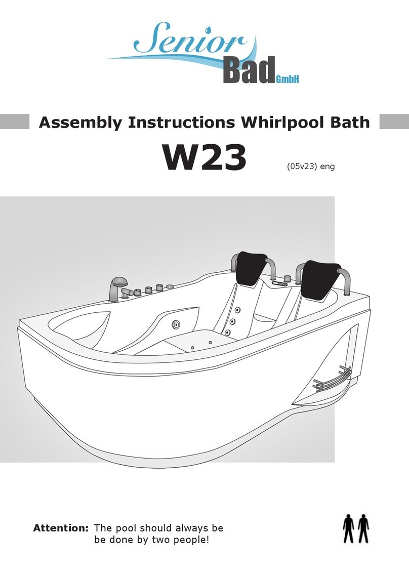
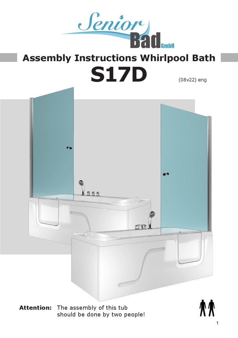
Senior Bad K55 User manual

Assembly Instructions Whirlpool Bath
K55 (07v20) eng
Attention:The pool should always be
be done by two people!
Senior
BadGmbH

2
Foreword
Dear customer, we are pleased that you have chosen this product. Please observe all
instructions before assembly and use and strictly follow the procedure below!
Please check the product for completeness rst. If there is any damage, please send us a
message with a short description and photos of the aected area. A responsible employee
will contact you as soon as possible and nd a solution together with you.
You have a 2-year legal warranty on all products.
Important information
Please note: The product is designed exclusively for private use. Our products are sub-
ject to constant further development. This may result in changes to the design and the
use of other components. We try to keep the following pages up to date. If you have any
questions regarding the design, please contact us at +49 35795 - 179 600 or by e-mail at
kundenservice@seniorbad.de. We are very grateful for any suggestions for improvement.
Please read the operating instructions carefully rst!
If you still have questions about the assembly, we will be happy to help you personally.
Complaints resulting from incorrect installation or use are excluded from the warranty!
Seals, hand showers, shower hoses and castors are wearing parts, therefore a warranty
period of 6 months applies here. The costs for replacement are not covered. Illuminants are
completely excluded from the warranty.
• Installation and assembly work should only be carried out by a skilled worker.
• Make sure that the bathtub is properly earthed. We recommend that any electrical
connections be made by trained professionals.
• The permissible water pressure should be approx. between 4 and 6 bar.
• From a hardness level of 10° (German hardness) we recommend the installation of a
softening device.
• Complaints based on limescale deposits are excluded from the warranty!

3
Sealing areas under/behind the bathtub
Sealing is compulsory - silicone is not enough!
The areas behind and under the bathtub must be tiled. Sealant joints - like silicone joints
- are not waterproong, but only maintenance and beauty joints! Only the use of bathtub
sealing tapes or e.g. sheet sealants comply with this DIN.
Waterproong according to DIN 18534
„This standard is therefore not only addressed to the waterproong specialist, but also to
those who are responsible for the overall planning and execution of the building and its
components, because the eect and durability of the waterproong depend on the coordi-
nated planning of all those involved.“
You as the installer are responsible for reliable waterproong alongside the planner and
tiler. „The waterproong must full its function for the intended service life with sucient
reliability.“
Waterproong must be planned so that it functions for the entire duration of use. In a
domestic bathroom, this can be an average of 20 to 25 years. In practice, this means laying
tiles or a membrane waterproong under the bath is mandatory. Note that the sealing area
at the transition from the oor to the wall must be at least 10 cm high.
Parameter
Rated voltage Frequency Total consumption Lighting
230V 50/60Hz 25W / with Whirlpool + 900W 10W
Fan Radio Frequency range Radio Whirlpool
5W 10W 88-108MHz 900W
The maximum water lling height is 34cm.

4
Please note:
1. The pool should be connected by an approved tradesman.
2. The pool should be assembled by a professional in accordance with these assembly
instructions. The power connection for the pool must be made by a certied electrician.
This person must also ensure sucient earthing to prevent accidents and malfunc-
tions.
3. Please have an electrician regularly check the function of the FI circuit breaker.
4. The statics of the oor must ensure that it can withstand the total weight of the pool
including water and one person.
5. The feet of the pool must stand on a rm, stable surface. The oor must be level.
6. Any damage found during unpacking must be reported immediately to the dealer, pref-
erably by taking photos and sending them to him.
Attention: This pool is not intended for permanent installation. It must be ensured that the
pool is installed in such a way that it is freely accessible for any maintenance or repair work.
Ensure that the bathroom oor is fully tiled and that there is a oor drain. The pool must not
be sunk into the oor!
Tools for the construction
Tools are not included in the package.
Check completeness!
Check that all the parts listed in the next section are complete. If you do not nd something
immediately, please look again carefully. Small parts in particular are easily overlooked due
to the large number of parts and the mass of the packaging.
Please do not dispose of the packaging until you are sure that it does not contain any small
parts.
Spirit level Drill/screwdriver Measuring tape Phillips / slotted
screwdriver
Open-end spanner

5
Product components
E
A Bath tub made of sanitary acrylic with removable apron/panel
B Right rear panel: The right rear panel is tted with the glass shelf.
C Shower panel: The panel is equipped with the back massage, the tting, the rain show-
er and optionally with the control display.
Please note that the shower panel has only been pre-assembled by the factory to
make it easier for you to assemble. It is absolutely necessary that you check all screw
connections and tighten them if necessary. This applies to the nozzles, the hoses on
the tting and the clamps.
DLeft rear panel *
*Please note that points B and D are reversed in the left-hand version.
A
BCD
Glass shelf

6
AB
16
B4
4x30
C
B5
x5
16
x6
4x30
x2
x1
C18
16
B4
4x30
Self-tapping
screw
Glass shelf Screw Nut Underlay
washer metal
Underlay Sili-
cone washer
Screw Upper arch
prole
Lower arch
prole
4a narrow
corner prole
4b wide corner
prole
Side window Flat gasket
2 x thick
Middle prole Screw Upper door
roller
Lower door
roller
Screw
Door seal,
F-seal
Glass door Screw Magnetic bar

7
Connections for water, sewage, electricity, telephone
Right version
1 Hot water 1/2 inch
2 Cold water 1/2 inch
Connections can also be on the
opposite side
3 Grey area = possible area for the
drain pipes, in the wall area the
drain can be up to a max. height of
6 cm to the centre of the hole
Drainage via exible connection
HT40 (supplied)
Connection possible without
dismantling the skirt/panel.
4 ATTENTION: leave the 15 cm Ø
around the white siphon (dark grey
area) under the drain free.
5a 230V 16A socket (or xed socket)
only for variant with radio, cable
length of transformer 1.20 m
5b 230V 16A (or xed socket) only for
version with whirlpool, cable length
of water pump 1.60 m
6Telephone connection
20 cm
10 cm
225 - 230 cm
115-125 cm
50 cm
25 cm
4 cm
10 cm
72 cm
42 cm
1
5a
5b
2
4
0-6 cm
6
3

8
Connections for water, sewage, electricity, telephone
Left version
1 Hot water 1/2 inch
2 Cold water 1/2 inch
Connections can also be on the
opposite side
3 Grey area = possible area for the
drain pipes, in the wall area the
drain can be up to a max. height of
6 cm to the centre of the hole
Drainage via exible connection
HT40 (supplied)
Connection possible without
dismantling the skirt/panel.
4 ATTENTION: leave the 15 cm Ø
around the white siphon (dark grey
area) under the drain free.
5a 230V 16A socket (or xed socket)
only for variant with radio, cable
length of transformer 1.20 m
5b 230V 16A (or xed socket) only for
version with whirlpool, cable length
of water pump 1.60 m
6Telephone connection
20 cm
10 cm
225 - 230 cm
115-125 cm
50 cm 25 cm
4 cm
10 cm
72 cm
42 cm
1
5a
5b
2
3
4
0-6 cm
6

9
Setting up and aligning the tub
Remove the skirt/panel and place the bathtub where you want it to stand later. Align it with
the help of a spirit level. Then pull the tub out approx. 40-50 cm from the corner. This is
necessary so that you can mount it on the back later.
You can adjust the height of the individual feet. It is very important that the tub stands
straight, does not tilt and that all feet are on the oor. It is also highly recommended that you
ll the nished tub with water and check that the water drains well. Please take some time
to do this.
TIP:
To make it easier for you to push the heavy tub into the corner after setting it up, we recom-
mend that you apply a lubricant to all feet. Then the tub will „glide“ better into the corner on
the tiles.
Mount shelf
TIP:
Mount the glass shelf on the back wall BEFORE
you place the back wall on the tub and screw it in
place.
Glass shelf

10
Screw back panels to panel and tray
The joint sealing tape (sponge rubber seal) supplied is glued to the two long corner proles
and to the panel (see diagram below).
Now place the left rear panel, then the panel and then the right rear panel on the tub. First
secure everything loosely with 1-2 screws and then align the assemblies in the slotted holes
and screw them together completely.
16 16
B4
88
Foam rubber seal
2-3 mm from the outer
edge, stick along the
panel.
Screw Nut Washer metal Silicone washer
Foam rubber
Foam rubber
Foam rubber
Foam rubber
Foam rubber
Foam rubber
Foam rubber

11
The panel is now simply placed on the tray and xed with the B5 screws.
Attention: The marking points on the tub serve as orientation for the subsequent screwing
of the rear panels to the shower tray. The base of the tub must not be drilled through!
x5
4x30
B5
Self-tapping
screw

12
The front frame
Pre-assemble frame
First take the magnetic strip C18 and insert it into the recess of the prole C4 (wide). Now
screw the corner prole C4 (narrow) to the two arch proles C3 for the bottom and C2 for
the top. The corner prole is milled out at the bottom corner, otherwise the prole will not t
on the tub. The side where the corner is not milled out goes to the top of the arch prole C2.
When the 4 proles are screwed together, the outer frame of the front is in place.
x1 x1 x1 x1
C18
x6
4x30
C18 TIP:
Each connection is
screwed 2x. To make
it easier and quicker to
stabilise the frame, we
recommend using only
one screw at a time.
When the frame is in
place, it is easier to t the
second screw.
broad narrow
Upper arch
prole
Lower arch
prole
2 corner
proles
Screw Magnetic bar

13
Prepare door
The diagram shows the preparation of the door, which is completely uncomplicated. The
only thing to note is that the roller C12 (with push-button) should be at the bottom, the other
C11 at the top. The door seal C13 must be tted so that it faces outwards.
x2 x1 x1x1
Lower door
roller
Glass door
Upper door
roller
Door seal,
F-seal

14
Final assembly of the front and the door
Now place the front frame on the tub and screw the corner proles C4 (wide) and C4
(narrow) to the rear walls. Now push the side pane C5 into the groove of the corner
prole C4 (narrow). Now place the middle prole C7 on the other side of the pane, push
it on and screw it to C3 and C2 at the top and bottom.
Now cut the wide at gaskets C6 to length and then push them from the outside into
the corner prole C4 (narrow) and into the middle prole C7. The best way to do this is
to use a small wooden wedge to press the at gaskets in evenly and completely. When
screwing the prole C3 with the screw C1 to the tub, make sure that the middle prole
C7 is exactly perpendicular. To do this, align the prole C7 with a spirit level and only
then pre-drill the hole for the screw C1 and screw it in. Now hang the door at the top,
then press the button on the roller at the bottom and thus clamp the door in the guide.
x1
x1
x1 x1
x1 x2
TIP:
The distance be-
tween C7 and C4
(narrow) must be
approx. 67 cm at the
top and bottom.
narrow broad
Screw
Middle prole
Corner proles
Screw Upper arch
prole
Lower arch
prole
Screw
Side window Flat gasket
2 x thick

15
TIP:
If the magnetic lock does not close the door because the door is not exactly perpendicular,
you can adjust the height of the door precisely on the upper rollers C11. This also applies if
you cannot engage the lower roller C12 in the guide in prole C3 because it is then too tight
or even too loose.
Last but not least, when everything is aligned and plumb, simply place the lid on top of the
cabin and screw it to the back walls.
Hose connections
Now connect the hoses for the individual functions to the four-way distributor at the top of
the tting. Starting at the top and then going clockwise, connect the hoses in the following
order. First the rain shower, then the back massage, then the bath spout and nally the
hand shower. The armoured hoses for the shower water supply come to the dual connec-
tion at the bottom, with the cold water on the left at the blue point and the hot water on the
right at the red point.
x5
B5
Self-tapping
screw

16
View of the connections from behind
The sketch shows an overview of the water connections, which are located behind the
shower panel.
Single-lever connection Thermostat connection
Install drain pipes
Now push the tub into place and align it once again. The drain is in the oor, but the waste
pipe can also be attached to a drain in the wall, but not higher than 6 cm so that the drain
is still guaranteed. The HT 40 waste water pipe used for this purpose is included in the
delivery.
Kaltwasser Warmwasser
Wanneneinlauf
RückenmassageHandbrause
Regenbrause
4fach-Umsteller
z.B. für - Regenbrause
- Handbrause
- Rückenmassage
- Fußmassage oder
Wanneneinlauf
- On/Off
(zu sich hin ziehen)
- Wasserdruck
- Temperatureinstellung
(nach links / rechts drehen)
Ground
Tub Tub
Ground
Wall
4-way diverter
e.g. for - rain shower
- hand shower
- back massage
- foot massage
or bath ller
4-way diverter
e.g. for - rain shower
- hand shower
- back massage
- foot massage
or bath ller
Rain shower
On/O
Water pressure
Hand shower Back massage
Bath spout
Cold water
Cold water
Hot water
Hot water
Temperature setting
- On/O
(pull towards you)
- Water pressure
- Temperature setting
(turn to the left / right)

17
Reattach apron
When the tub is nished and professionally connected, the sides are faced again.
To do this, simply tilt the tub slightly and raise it to click the side parts underneath, now just
screw them in place and put the cover cap on the screw.
Sealing
It is necessary to draw a silicone joint between the tub and the C3 prole as well as be-
tween the front glass pane and the C3 prole from the inside (see illustration).
If you wish, you can of course also draw a silicone joint between the tub and the rear walls.
When doing so, however, it is essential that you leave the three drainage openings centrally
under the rear walls, the glass front next to the doors and the panel open. Please do NOT
seal these with silicone.
Attention:
Please seal the dashed areas
from the inside with silicone!
1. all around between the tub
and the aluminium proles
2. only in the front area be-
tween front glass and front
curved aluminium prole

18
Commissioning/leak test
For the leak test, please now connect the water and the waste water with the hose connec-
tions. It is important that the tub continues to stand away from the wall so that you can still
get behind the shower panel.
Before you put the line under water pressure, please note that the shower panel has only
been pre-assembled by the factory to make it easier for you to set it up. It is essential that
you recheck all screw connections and tighten them if necessary. This applies to the seat,
the nozzles and the clamps. Only when all this has been checked may you open the water.
Now test all the functions that have to do with water, one after the other. Check the hand
shower, then the rain shower and the back massage. It is best to do this in pairs. One
stands in front of or inside the shower cubicle, the other stands behind the shower cubicle
and looks at the hose connection and the function that is currently being tested. If a screw
connection is not properly tight, check whether the seal in the screw connection is properly
seated and whether it is screwed tight enough. After the tightness test, the electrical func-
tions can now be tested. When the plug is plugged in, you can test the light, radio, etc.
Operating display
Transmitter reset
Volume „+++“
Volume „---“
Light Paneel
Hands-free telephone
system (on/o)
Control unit on/o
Channel search (Radio)
Light
Fan
Radio on/o

19
Shower maintenance and cleaning
1. Clean the tub and shower enclosure with a mild liquid detergent and a soft cloth.
Caution: Never use acetone, cleaning agents containing ammonia or coarse-grained
scouring agents!
2. Clear the shower drain regularly of hair and the like to prevent clogging.
3. Use an acrylic care product for the bathtub and the panel to protect the surface from
scratches.
„Lotus eect set“ against dirt deposits, limescale/water stains
Contents:
1x NANO NT GLASS & CERAMIC (easy to clean)
1x NANO NT CLEANER
1x CLEANING WIPE
1x POLISHING CLOTH
1x PROTECTIVE GLOVES
Resistant to steam cleaners * Very durable long-term protection * Lasts for many
months, depending on use * Minimal care and cleaning eort * No more expensive
cleaning agents required * Dirt can no longer adhere or is easier to clean (easy-to-clean)
* Very easy to use
THE NANO NT GLASS & CERAMIC 2 COMPONENT SET is a coordinated cleaning and
surface nishing system that generates a very high-quality and long-lasting „easy-to-clean-
eect“ on glass and ceramic surfaces.
The applied material creates a thin lm on the surface that reduces the adhesion of dirt and
foreign substances and allows water to roll o better.
4. Small scratches can be polished with e.g. toothpaste and a soft cloth.
5. Make sure that the drains, which are located in the centre of the bathtub underneath
the rear walls, are always open. Otherwise, if they become blocked, the water will not
drain back into the inside of the tub. There is a risk that too much water will accumulate
and then run out over the protective wall.
6. Before using the whirlpool system for the rst time, it should be rinsed with disinfectant.
It is then sucient to repeat the disinfection after approx. 5 baths. Disinfection should
also be carried out if the whirlpool system is not used for a longer period of time.

20
You can order our „Lotus -Eect Set“ at:
E-mail: kundenser[email protected]
Online shop: www.seniorbad.de
Phone: +49 35795 - 179 600
Fax: +49 35795 - 179 699
Note
Each pool is assembled, connected, tested and repacked at the factory for testing purpos-
es. As our products undergo several checks during manufacture, small amounts of residual
water may be present in parts of the product.
Warranty and service
We grant a 2-year warranty for our products. A warranty period of 6 months applies to
included wear parts such as seals, hand showers, shower hoses, castors. The costs for
replacement are not covered. Spare parts can be ordered from our customer service.
Defects that can be traced back to calciferous or iron-rich water are excluded from the war-
ranty. Please describe the spare part exactly - preferably add the abbreviated designation
(letter / number) used in this booklet as well as the exact type of cabin (e.g. K55). We are
always open to your comments and suggestions.
Recycling
For the disposal of the product‘s electronics, the Waste Electrical and Electronic Equipment
Act (Waste Electrical and Electronic Equipment Act) applies. The „old device“ must then be
taken to an appropriate collection point.
We recommend that you remove the control unit, the lighting unit and the display and take
these parts to the electrical/electronic collection point. The remaining large „residue“ can be
treated as usual (local variant - such as bulky waste collection ...).
Senior
BadGmbH
Table of contents
Other Senior Bad Bathtub manuals
Popular Bathtub manuals by other brands
Whirlpool
Whirlpool Ariel ARL-702 installation manual

Kohler
Kohler K-1151 Homeowner's guide

American Standard
American Standard 3052OD.X0X Installation instructions and owner's manual
Kohler
Kohler K-1111-H2 Roughing-In Guide
Kohler
Kohler K-1158 Roughing-In Guide
Kohler
Kohler Hourglass K-1209-LA Roughing-In Guide

