Senju Sprinkler HF-RES User manual
www.senjusprinkler.com Document No. U028705 • 01-26-2022
Page 1 of 7
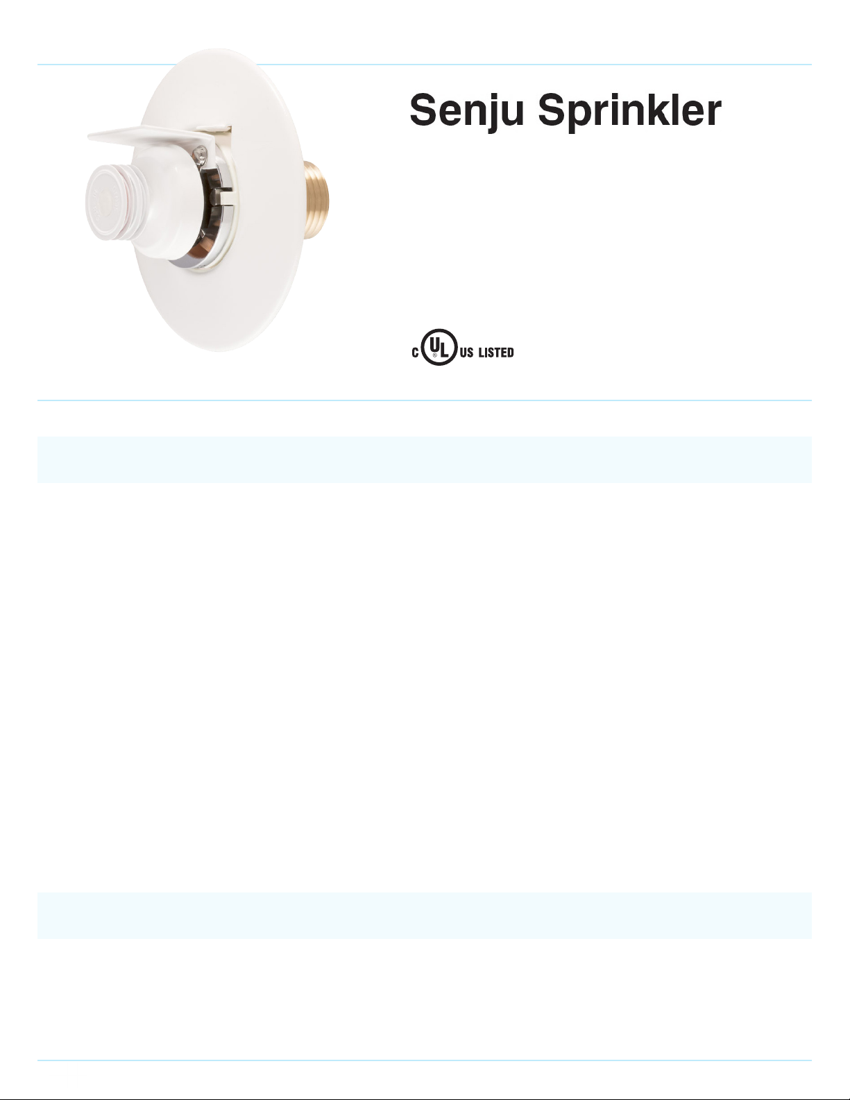
The Model HF-RES Residential Flush Horizontal Sidewall Sprinklers are automatic sprinklers of the compressed fusible
solder type. They are decorative, low prole, ush mount sprinklers. The Frame and Cover of the sprinkler hide the Deector
and Valve Cap assemblies. (Reference Figure 1) The Model HF-RES is designed for use in residential occupancies such
as homes, apartments, dormitories, and hotels. When aesthetics is the major consideration, the Model HF-RES should
be your rst choice.
They are to be used in wet pipe residential sprinkler systems for one- and two-family dwellings and manufactured homes
per NFPA 13D; wet pipe residential sprinkler systems for residential occupancies up to and including four stories in height
per NFPA 13R; or, wet pipe sprinkler systems for the residential portions of any occupancy per NFPA 13.
The Model HF-RES has a 4.2 (60.5 LPM / bar1/2) K-factor which provides very low design ow rates at reduced residual
pressures, enabling smaller pipe sizes and water supply requirements.
The ush design of the Model HF-RES features a separable escutcheon providing 3/16 inch (4.7 mm) of total adjustment.
This adjustment reduces the accuracy to which the xed pipe drops to the sprinklers must be cut to help assure a perfect
t installation.
The Model HF-RES has been designed with heat sensitivity and water distribution characteristics proven to help in the
control of residential res to improve the chance for occupants to escape or be evacuated. However, residential re
sprinkler systems are not a substitute for intelligent re safety awareness or re safety construction required by building
codes.
GENERAL DESCRIPTION
Residential Flush Horizontal Sidewall Sprinkler
(PTFE gasketed orice seal design)
Model HF-RES
K-Factor: 4.2 •SIN: SS4423
WARNINGS
The Model HF-RES Residential Flush Horizontal Sidewall Sprinklers described herein must be installed and maintained
in compliance with this document, as well as with the applicable standards of the National Fire Protection Association,
in addition to the standards of any authorities having jurisdiction. Failure to do so may impair the integrity of these
devices.

www.senjusprinkler.com Document No. U028705 • 01-26-2022
Page 2 of 7
• Approvals:
{cULus Listed
• Sprinkler Identication Number (SIN): SS4423
• Maximum Working Pressure: 175psi (12.1 bar)
• Discharge Coefcient (Nominal K-Factor):
{K = 4.2 GPM/psi1/2 (60.5 LPM/bar1/2)
• Temperature Rating:
{162°F (72°C)
• Horizontal Adjustment: 3/16 inch (4.7 mm)
• Finishes:
{Sprinkler and Escutcheon: White Painted,
Black Painted, Dark Brown Painted, Chrome Plated
• Physical Characteristics: Dezincication resistant
Copper Alloy body and PTFE gasketed orice seal design. Figure 1: Model HF-RES K = 4.2
Residential Flush Horizontal Sidewall Sprinkler
TECHNICAL DATA
FIGURE 1
MODEL K=4.2 RESIDENTIAL FLUSH HORIZONTAL
SIDE-WALL SPRINKLER
Year of Manufacture
Temperature Rating (162 F)
Listing Mark
Country Origin
I.D Number (SIN)
Marking
Four Wrench Slots
5-Cover (Copper)
7-Fusible Metal
2-Frame (Bronze)
1-Body (Copper Alloy)
6
6-Heat Collector (Copper)
8-Sub Deflector (Copper Alloy)
4-Gasket (PTFE)
3-Deflector (Copper Alloy)
COMPONENTS (MATERIALS) :
74
1/2" NPT
2- 7/16"
2
1 3 8 5
9-Valve Cap (Copper Alloy)
9
FIGURE 2
Normal Condition
Operation
W
ater Discharge
FIGURE 4
Ratchet
Socket HF-H
Protective Cap
FIGURE 3
53/64"
MOUNTING SURFACE
CENTER MARK
Min. 1/8" (3mm)
MAKE A SPACE HERE
2- 3/8" (60mm)
WALL HOLE
DIAMETER
DO NOT
OVER-TIGHTEN
BODY
REDUCER
REDUCER
CORRECT
INCORRECT
TOLERANCE LIMIT OF
BACK-WALL LEVEL
WALL
WALL SURFACE
WALL
FIGURE 5
Cap Removal Tool
Groove of cap
Step 2
Pull out
Step1
HF-RES Sprinkler
Protective Cap
FIGURE 6
ESCUTCHEON
MOUNTING
SURFACE
WALL
TOP OF
DEFLECTOR
FIGURE 7
ESCUTCHEON
ESCUTCHEON
THERE MUST
NOT BE SPACE
MOUNTING SURFACE
CORRECT
ESCUTCHEON
INCORRECT INCORRECT
WALL
Because of the above cited stipulations and the varied nature of residential type architecture, there will be some
compartment designs which cannot be fully sprinklered in accordance with the recommendations of NFPA 13, 13D,
or 13R, In the event of this condition, consult the authorities having jurisdiction for guidance and approval.
It is the responsibility of the installing contractor to provide a copy of this document to the owner or their representative,
and in turn, it is the obligation of the owner to provide a copy of this document to a succeeding owner.
The owner is responsible for maintaining their re protection system and devices in proper operating condition. The
installing contractor or sprinkler manufacturer should be contacted relative to any questions.
OPERATION
The Sprinkler assembly contains a small fusible solder element. When exposed to sufcient heat from a re, the solder
melts and enables the internal components of the sprinkler to be released. At this point the sprinkler activates with the
deector moving into its operated position (Reference Figure 2), permitting water to ow.
Figure 2: Operation Process (For illustrative purposes only)
FIGURE 1
MODEL K=4.2 RESIDENTIAL FLUSH HORIZONTAL
SIDE-WALL SPRINKLER
Year of Manufacture
Temperature Rating (162 F)
Listing Mark
Country Origin
I.D Number (SIN)
Marking
Four Wrench Slots
5-Cover (Copper)
7-Fusible Metal
2-Frame (Bronze)
1-Body (Copper Alloy)
6
6-Heat Collector (Copper)
8-Sub Deflector (Copper Alloy)
4-Gasket (PTFE)
3-Deflector (Copper Alloy)
COMPONENTS (MATERIALS) :
74
1/2" NPT
2- 7/16"
21 3 8 5
9-Valve Cap (Copper Alloy)
9
FIGURE 2
Normal Condition
Operation
W
ater Discharge
FIGURE 4
Ratchet
Socket HF-H
Protective Cap
FIGURE 3
53/64"
MOUNTING SURFACE
CENTER MARK
Min. 1/8" (3mm)
MAKE A SPACE HERE
2- 3/8" (60mm)
WALL HOLE
DIAMETER
DO NOT
OVER-TIGHTEN
BODY
REDUCER
REDUCER
CORRECT
INCORRECT
TOLERANCE LIMIT OF
BACK-WALL LEVEL
WALL
WALL SURFACE
WALL
FIGURE 5
Cap Removal Tool
Groove of cap
Step 2
Pull out
Step1
HF-RES Sprinkler
Protective Cap
FIGURE 6
ESCUTCHEON
MOUNTING
SURFACE
WALL
TOP OF
DEFLECTOR
FIGURE 7
ESCUTCHEON
ESCUTCHEON
THERE MUST
NOT BE SPACE
MOUNTING SURFACE
CORRECT
ESCUTCHEON
INCORRECT INCORRECT
WALL

www.senjusprinkler.com Document No. U028705 • 01-26-2022
Page 3 of 7
The Model HF-RES Residential Flush Horizontal Sidewall Sprinklers must only be installed and utilized in accordance with
the following described criteria, which are provided by the manufacturer.
DESIGN CRITERIA
Notes
Residential Fire Sprinkler Systems should only be designed and installed by those component and completely familiar with
automatic sprinkler system design, installation procedures, and techniques. Several criteria may apply to the installation and
usage of each sprinkler. Consequently, it is recommended that the sprinkler system designer review and develop a working
understanding of the complete list of criteria prior to initiating the design of the sprinkler system.
Questions concerning sprinkler installation and usage criteria, which are not covered by the following instructions, should be
submitted to your contracted company. Include sketches and technical details, as appropriate.
In some instances, the requirements of this document may concern specications which are more stringent and which take
precedence over those specied in NFPA 13, NFPA 13D, NFPA 13R, or by the authority having jurisdiction.
The spray from the sprinkler is distributed outward and downward from the sprinkler deector in a semicircle. Consequently,
the sprinklers must be located such that there will not be any blind spaces shielded from spray by partitions, room dividers,
overhangs or other parts of the dwelling structure.
The number of sprinklers within each compartment (as dened by NFPA 13D, 13R, or 13) must be kept as few as possible while
observing all guidelines relating to obstructions and spacing.
Use only the escutcheon provided with the Model HF-RES. The sprinkler must be secured in position by rmly fastening the
sprinkler system piping to the structure. If the sprinkler is not properly secured in position, reaction forces resulting from
sprinkler operation could alter its orientation and its water distribution pattern.
The sprinkler escutcheon cannot be used to hold the sprinkler in position.
Obstruction to Water Distribution
Locations of sprinklers must follow the obstruction rules of NFPA 13, 13D and 13R for Residential Sprinklers.
General Service Conditions
The Model HF-RES must only be utilized in wet pipe sprinkler systems.
Heat Source Criteria
Refer to NFPA 13D, 13R or 13 for the requirements relating to the prevention of possible activation of the Heat Responsive
Element of Model HF-RES, due to the exposure of a heat source other than an actual re.
Precautionary Warnings for Corrosive Environments
The Model HF-RES sprinklers should not be installed where they may be subjected to a corrosive environment including
the following:
1. Chlorine ion and Chloride environment
Stress corrosion cracking may be caused by exposure to environments with Chlorine ion and Chloride. Exposure to
this environment may result in sprinklers operating under non-re conditions or not operating when exposed to an
actual re.
2. Sprinkler system piping with Copper
Sprinkler systems should be constructed in compliance with the applicable standards and the requirements for
copper piping when copper piping is used in the sprinkler system. (Reference standards NFPA 13, ASTM B813, ASTM
B828, and CDA (Copper Development Association) – Solder Joint)
All residual ux must be removed from the interior and exterior of the copper piping by thoroughly ushing before
installation of the Sprinkler Heads. Otherwise, residues of ux may cause corrosion and/or leakage in the sprinkler
system.

www.senjusprinkler.com Document No. U028705 • 01-26-2022
Page 4 of 7
Hydraulic Design Criteria
The minimum required sprinkler ow rates for systems designed to NFPA 13D or 13R are given in Table A as a function of
temperature rating and the maximum allowable coverage areas. The sprinkler ow rate is the minimum required discharge
from the most hydraulically demanding sprinkler from each of the total number of “design sprinklers” as specied in NFPA
13D or 13R.
For systems designed to NFPA 13, the number of design sprinklers is to be the four most hydraulically demanding
sprinklers. The minimum required discharge from each of the four sprinklers is to be the greater of the followings:
• The ow rates given in Table A for NFPA 13D and 13R as a function of temperature rating and maximum allowable
coverage area.
• A minimum discharge 0.1gpm/sq.ft. [4.07(L/min)/sq.m] over the “design area” comprised of the four most hydraulically
demanding sprinklers for the actual coverage areas being protected by the four sprinklers.
Sprinkler Spacing Criteria
The minimum spacing between sprinklers is 8 feet (2.4m). The maximum spacing between sprinklers cannot go beyond
the coverage area calculated by using the specic hydraulic factors. (Ref. Table A)
Operational Sensitivity Criteria
For proper operational sensitivity, the model HF-RES must be installed under smooth, at, horizontal ceilings as outlined
in the applicable installation standard recognized by the approval agency (e.g. UL recognizes NFPA 13, 13D and 13R)
The distance from the Top of the sub-deector to the ceiling has to be within 4-6 inches.
The Model HF-RES must NOT be used above or below open-gridded type suspended ceilings; beneath softs or beams
exceeding 3 inches in height or joists, or ducts having a height of more than 3 inches located within the sprinkler coverage
areas.
Beams having a height of more than 3 inches may be located with their centerlines along the boundaries separating
adjacent sprinkler coverage areas.
Table A. NFPA 13D AND NFPA 13R HYDRAULIC DESIGN CRITERIA for Model SS4423
For systems with ceiling types smooth at horizontal, or beamed, or sloped, in accordance with NFPA 13D, 13R or 13 as
applicable.
Maximum
Coverage
Area(a)
Ft. x Ft.
(m x m)
Maximum
Spacing
Ft.
(m)
Ordinary Temperature Rating 162˚F (72˚C)
Flow(b) GPM
(LPM)
Pressure(b)
PSI (bar)
Top Sub
Deector to
Ceiling
Installation
Type
Minimum
Spacing Ft.
(m)
12 x 12
(3.7 x 3.7)
12
(3.7)
13
(49.2)
9.6
(0.66)
4 to 6 inches Flush 8
(2.4)
14 x 14
(4.3 x 4.3)
14
(4.3)
16
(60.6)
14.5
(1.00)
16 x 16
(4.9 x 4.9)
16
(4.9)
20
(75.7)
22.7
(1.56)
a. For coverage area dimensions less than the above mentioned, it needs to use the minimum required ow for the Next
Higher Coverage Area listed.
b. Requirement is based on minimum ow in GPM (LPM) from each sprinkler. The associated residual pressures are
calculated using the nominal K-Factor. Refer to Hydraulic Design Criteria Section for details.
www.senjusprinkler.com Document No. U028705 • 01-26-2022
Page 5 of 7
INSTALLATION
The Model HF-RES must be installed in accordance with the following instructions:
NOTES
Do not use sprinklers which have been subjected to potential mechanical damage. Do not use sprinklers which show deformation
or cracking in either the sprinkler or protection cap.
The Protective Cap must remain on the sprinkler during installation and until the ceiling installation is completed. The Protective
Cap must be removed to place the sprinkler in service.
Use a torque of 7 to 14 ft·lbs (9.5 to 19.0 N·m) to achieve a 1/2 inch NPT sprinkler joint. If you exceed the recommended maximum
torque, this could result in damage to the sprinkler inlet, which may lead to leakage from the sprinkler.
Use only HF-H model wrench socket for installation of HF-RES sprinklers. Use of any other wrench or socket is prohibited and
may cause damage to the sprinkler.
Do not attempt to compensate for insufcient adjustment in an Escutcheon Plate by under- or over-tightening the sprinkler.
Readjust the position of the sprinkler tting to suit.
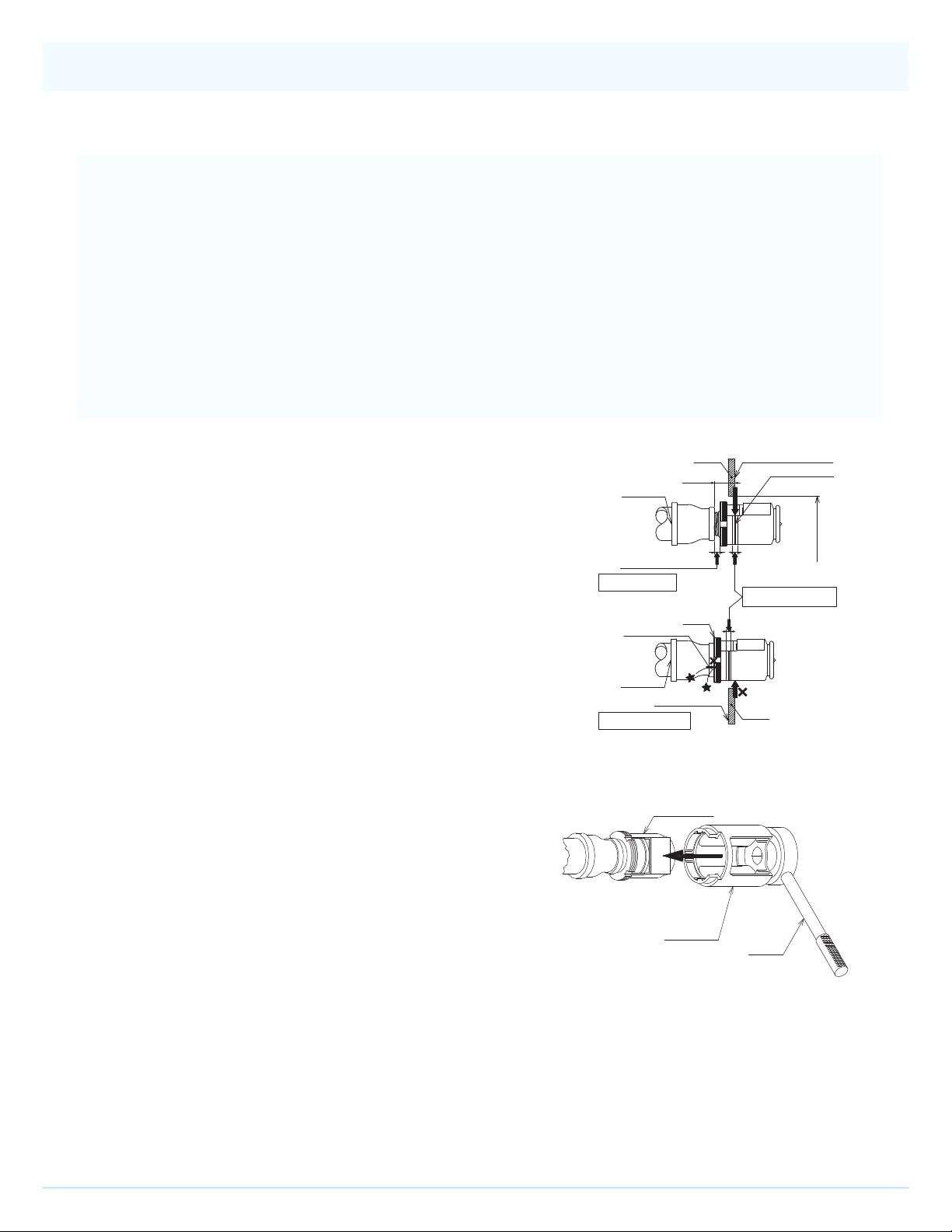
Installation Steps
Step 1: The sprinkler must be installed only in the sidewall position
with their centerline of waterway perpendicular to the back wall
and parallel to the ceiling. The word “TOP” on the sub-deector
has to face towards the ceiling with the front edge of the sub-
deector parallel to the ceiling.
Step 2: Install the sprinkler tting so that the distance from the
face of the tting to the mounting surface will be nominally 53/64
inch (21.0mm) as shown in Figure 3.
Step 3: With pipe thread sealant applied to the pipe threads, hand
tightens the Sprinkler into the sprinkler tting.
FIGURE 1
MODEL K=4.2 RESIDENTIAL FLUSH HORIZONTAL
SIDE-WALL SPRINKLER
Year of Manufacture
Temperature Rating (162 F)
Listing Mark
Country Origin
I.D Number (SIN)
Marking
Four Wrench Slots
5-Cover (Copper)
7-Fusible Metal
2-Frame (Bronze)
1-Body (Copper Alloy)
6
6-Heat Collector (Copper)
8-Sub Deflector (Copper Alloy)
4-Gasket (PTFE)
3-Deflector (Copper Alloy)
COMPONENTS (MATERIALS) :
74
1/2" NPT
2- 7/16"
21 3 8 5
9-Valve Cap (Copper Alloy)
9
FIGURE 2
Normal Condition
Operation
W
ater Discharge
FIGURE 4
Ratchet
Socket HF-H
Protective Cap
FIGURE 3
53/64"
MOUNTING SURFACE
CENTER MARK
Min. 1/8" (3mm)
MAKE A SPACE HERE
2- 3/8" (60mm)
WALL HOLE
DIAMETER
DO NOT
OVER-TIGHTEN
BODY
REDUCER
REDUCER
CORRECT
INCORRECT
TOLERANCE LIMIT OF
BACK-WALL LEVEL
WALL
WALL SURFACE
WALL
FIGURE 5
Cap Removal Tool
Groove of cap
Step 2
Pull out
Step1
HF-RES Sprinkler
Protective Cap
FIGURE 6
ESCUTCHEON
MOUNTING
SURFACE
WALL
TOP OF
DEFLECTOR
FIGURE 7
ESCUTCHEON
ESCUTCHEON
THERE MUST
NOT BE SPACE
MOUNTING SURFACE
CORRECT
ESCUTCHEON
INCORRECT INCORRECT
WALL
Figure 3: Installation
Figure 4: Ratchet & Socket
Step 4: Wrench tighten the Sprinkler using only the Socket
HF-H or Ratchet (3/8″drive) & Socket HF-H Combination (Ref.
Figure 4). Put the Sprinkler Socket over the sprinkler without
the sub-deector hit till the socket touches the body of the
sprinkler. Turn the socket till the wrench recess of the Socket
can be applied to the sprinkler wrenching area (Ref. Figure 4).
Special care must be exercised to avoid damage to the sprinkler
while you remove the socket wrench from the sprinkler as well.
FIGURE 1
MODEL K=4.2 RESIDENTIAL FLUSH HORIZONTAL
SIDE-WALL SPRINKLER
Year of Manufacture
Temperature Rating (162 F)
Listing Mark
Country Origin
I.D Number (SIN)
Marking
Four Wrench Slots
5-Cover (Copper)
7-Fusible Metal
2-Frame (Bronze)
1-Body (Copper Alloy)
6
6-Heat Collector (Copper)
8-Sub Deflector (Copper Alloy)
4-Gasket (PTFE)
3-Deflector (Copper Alloy)
COMPONENTS (MATERIALS) :
74
1/2" NPT
2- 7/16"
21 3 8 5
9-Valve Cap (Copper Alloy)
9
FIGURE 2
Normal Condition
Operation
W
ater Discharge
FIGURE 4
Ratchet
Socket HF-H
Protective Cap
FIGURE 3
53/64"
MOUNTING SURFACE
CENTER MARK
Min. 1/8" (3mm)
MAKE A SPACE HERE
2- 3/8" (60mm)
WALL HOLE
DIAMETER
DO NOT
OVER-TIGHTEN
BODY
REDUCER
REDUCER
CORRECT
INCORRECT
TOLERANCE LIMIT OF
BACK-WALL LEVEL
WALL
WALL SURFACE
WALL
FIGURE 5
Cap Removal Tool
Groove of cap
Step 2
Pull out
Step1
HF-RES Sprinkler
Protective Cap
FIGURE 6
ESCUTCHEON
MOUNTING
SURFACE
WALL
TOP OF
DEFLECTOR
FIGURE 7
ESCUTCHEON
ESCUTCHEON
THERE MUST
NOT BE SPACE
MOUNTING SURFACE
CORRECT
ESCUTCHEON
INCORRECT INCORRECT
WALL
Step 5: Use the “tolerance limit of back-wall level” indicator on the Protective Cap to check for proper installation depth
(Ref. Figure 3) Relocate the sprinkler tting as necessary. If desired the Protective Cap may also be used to locate the
center of the clearance hole by gently pushing the back wall material against the center point of the Cap.
Step 6: After the back wall has been completed with the 2-3/8inch (60mm) diameter clearance hole, use the Protective
Cap Removal Tool (Ref. Figure 5) to remove the Protective Cap and then push on the Escutcheon until its ange just
comes in contact with the back wall (Ref. Figures 6 & Figure 7).

www.senjusprinkler.com Document No. U028705 • 01-26-2022
Page 6 of 7
FIGURE 1
MODEL K=4.2 RESIDENTIAL FLUSH HORIZONTAL
SIDE-WALL SPRINKLER
Year of Manufacture
Temperature Rating (162 F)
Listing Mark
Country Origin
I.D Number (SIN)
Marking
Four Wrench Slots
5-Cover (Copper)
7-Fusible Metal
2-Frame (Bronze)
1-Body (Copper Alloy)
6
6-Heat Collector (Copper)
8-Sub Deflector (Copper Alloy)
4-Gasket (PTFE)
3-Deflector (Copper Alloy)
COMPONENTS (MATERIALS) :
74
1/2" NPT
2- 7/16"
21 3 8 5
9-Valve Cap (Copper Alloy)
9
FIGURE 2
Normal Condition
Operation
W
ater Discharge
FIGURE 4
Ratchet
Socket HF-H
Protective Cap
FIGURE 3
53/64"
MOUNTING SURFACE
CENTER MARK
Min. 1/8" (3mm)
MAKE A SPACE HERE
2- 3/8" (60mm)
WALL HOLE
DIAMETER
DO NOT
OVER-TIGHTEN
BODY
REDUCER
REDUCER
CORRECT
INCORRECT
TOLERANCE LIMIT OF
BACK-WALL LEVEL
WALL
WALL SURFACE
WALL
FIGURE 5
Cap Removal Tool
Groove of cap
Step 2
Pull out
Step1
HF-RES Sprinkler
Protective Cap
FIGURE 6
ESCUTCHEON
MOUNTING
SURFACE
WALL
TOP OF
DEFLECTOR
FIGURE 7
ESCUTCHEON
ESCUTCHEON
THERE MUST
NOT BE SPACE
MOUNTING SURFACE
CORRECT
ESCUTCHEON
INCORRECT INCORRECT
WALL
Figure 6: InstallationFigure 5: Protective Cap Removal
Do not continue to push on the Escutcheon such that it lifts a wall out of its normal position. If the Escutcheon cannot
be engaged with the Sprinkler, or the Escutcheon cannot be engaged sufciently to contact the back wall, relocate the
sprinkler tting as necessary.
Figure 7: Installation (Correct and Incorrect)
FIGURE 1
MODEL K=4.2 RESIDENTIAL FLUSH HORIZONTAL
SIDE-WALL SPRINKLER
Year of Manufacture
Temperature Rating (162 F)
Listing Mark
Country Origin
I.D Number (SIN)
Marking
Four Wrench Slots
5-Cover (Copper)
7-Fusible Metal
2-Frame (Bronze)
1-Body (Copper Alloy)
6
6-Heat Collector (Copper)
8-Sub Deflector (Copper Alloy)
4-Gasket (PTFE)
3-Deflector (Copper Alloy)
COMPONENTS (MATERIALS) :
74
1/2" NPT
2- 7/16"
21 3 8 5
9-Valve Cap (Copper Alloy)
9
FIGURE 2
Normal Condition
Operation
W
ater Discharge
FIGURE 4
Ratchet
Socket HF-H
Protective Cap
FIGURE 3
53/64"
MOUNTING SURFACE
CENTER MARK
Min. 1/8" (3mm)
MAKE A SPACE HERE
2- 3/8" (60mm)
WALL HOLE
DIAMETER
DO NOT
OVER-TIGHTEN
BODY
REDUCER
REDUCER
CORRECT
INCORRECT
TOLERANCE LIMIT OF
BACK-WALL LEVEL
WALL
WALL SURFACE
WALL
FIGURE 5
Cap Removal Tool
Groove of cap
Step 2
Pull out
Step1
HF-RES Sprinkler
Protective Cap
FIGURE 6
ESCUTCHEON
MOUNTING
SURFACE
WALL
TOP OF
DEFLECTOR
FIGURE 7
ESCUTCHEON
ESCUTCHEON
THERE MUST
NOT BE SPACE
MOUNTING SURFACE
CORRECT
ESCUTCHEON
INCORRECT INCORRECT
WALL
CARE & MAINTENANCE
The following instructions must be implemented for the maintenance and service of the Model HF-RES.
Notes
Wet pipe sprinkler systems must be maintained at a minimum temperature of 40°F / 4°C to prevent freezing and bursting of the
pipe and/or sprinklers.
Automatic sprinklers are not to be tested with a heat source. Operation of the heat responsive element can result.
Absence of an Escutcheon Plate may delay the time to sprinkler operation in a re situation.
Before closing a re protection system main control valve for maintenance work on the re protection system, which it controls,
permission to shut down the affected re protection system must be obtained from the proper authorities and all personnel who
may be affected by this action must be notied.
Do NOT enclose sprinklers within drapes, curtains, or valances.
Do NOT hang anything from the sprinklers.

www.senjusprinkler.com Document No. U028705 • 01-26-2022
Page 7 of 7
Do NOT cleanse the sprinklers with soap and water, detergents, ammonia, cleaning uids, or other chemicals. Remove dust,
lint, cobwebs, cocoons, insects, and larvae by gently brushing with a feather duster or gently vacuuming with a soft bristle (i.e.,
dusting) brush attachment.
Exercise suitable safety precautions in the use and storage of highly ammable materials. The rapid rate of re development and
spread of which can be caused by such materials can reduce the ability of the sprinkler system to aid in the control of a re in
which they are involved.
Sprinklers, which are found to be leaking or exhibiting visible signs of corrosion, must be replaced.
Automatic Sprinklers must be kept in a cool and dry place. Automatic sprinklers must never be painted, plated, coated, or
otherwise altered after leaving the factory. Modied or over heated sprinklers must be replaced.
Care must be exercised to avoid damage to the sprinklers-before, during, and after installation. Sprinklers damaged by dropping,
striking, wrench twist / slippage, or the like, must be replaced.
The model HF-RES must only be replaced with Horizontal Sidewall sprinklers which are listed for residential re protection
service and which have the same nominal K-factor, the same coverage area, and the same or lower ow ratings (as indicated
under “Hydraulic Design Criteria”).
When remodeling, such as by adding false beams or light xtures or changing the location of compartment walls, rst verity that
the new construction will not violate the installation requirements of the applicable standards of NFPA. Alter the new construction
and/or the sprinkler system to suit the requirements of this document and the applicable NFPA regulations.
The owner is responsible for the maintenance of the sprinkler system, including inspection and testing, its compliance with
this documents, as well as the standards of the National Fire Protection Association (e.g., NFPA 25), and the regulations of any
other authorities having jurisdiction. The owner should direct any questions regarding the above rules and regulations to the
installing contractors or the sprinkler manufacturer. It is recommended that automatic sprinkler systems be inspected, tested,
and maintained by a qualied Inspection Service in accordance with NFPA 25.
ORDER PROCEDURE
Sprinkler
• Model: HF-RES
SIN: SS4423, Residential Flush Horizontal Sidewall Sprinkler, K4.2, Temperature: 162°F (72°C)
• Finishes: White Painted, Black Painted, Dark Brown Painted, Chrome Plated
Escutcheon
• Escutcheon for HF-RES Flush Horizontal Sidewall, O.D. 3 inch (φ75mm), Order Separately from Sprinkler
• Finishes: White Painted, Black Painted, Dark Brown Painted, Chrome Plated
Tools and Accessories
• Socket HF-H
For use with a 3/8″drive ratchet (not included)
• Cap Removal Tool for HF
When placing an order, please contact a local distributor with the following information (Model Name and Finish).
This manual suits for next models
1
Table of contents
Other Senju Sprinkler Irrigation System manuals

Senju Sprinkler
Senju Sprinkler FR-QR User manual

Senju Sprinkler
Senju Sprinkler CN-RES User manual

Senju Sprinkler
Senju Sprinkler RC-QR User manual

Senju Sprinkler
Senju Sprinkler RC-QR-EC User manual

Senju Sprinkler
Senju Sprinkler ZN-UF User manual

Senju Sprinkler
Senju Sprinkler FR-RES User manual

Senju Sprinkler
Senju Sprinkler HF-RES User manual

Senju Sprinkler
Senju Sprinkler RC-QR User manual

Senju Sprinkler
Senju Sprinkler ZN-RES User manual

Senju Sprinkler
Senju Sprinkler CN-QR User manual


