Design
Criteria
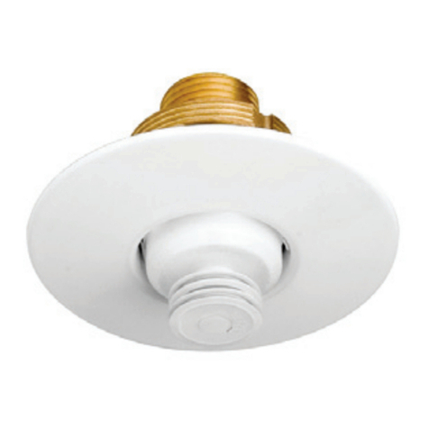
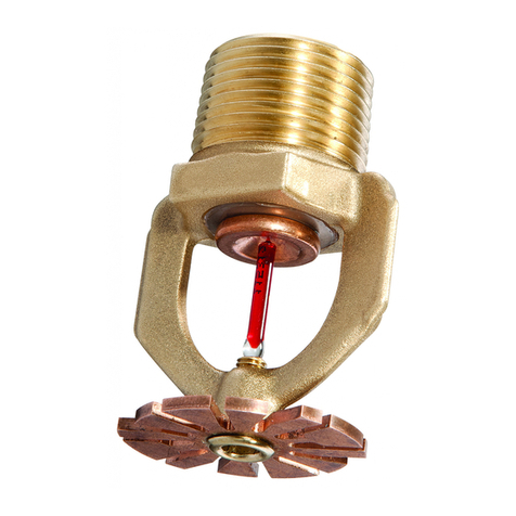
TYCO Series DS-C 3 mm bulb-type Dry
Type Concealed Pendent Sprinklers
(TY3535) are UL and C-UL Listed
as quick response, standard spray
sprinklers for use in accordance with
the current NFPA standard.
Series DS-C 5 mm bulb-type Dry Type
Concealed Pendent Sprinklers (TY3555)
are UL and C-UL Listed as standard
response, standard spray sprinklers
for use in accordance with the current
NFPA standard.
Series DS-C Dry Type Sprinklers are
only listed when installed with Series
RFII Concealed Cover Plates having
a factory-applied painted or metallic
nish.
Series DS-C Dry Type Sprinklers must
not be used in applications where the
air pressure above the ceiling is greater
than that below. Down drafts through
the Support Cup could delay sprinkler
operation in a re situation.
Sprinkler Fittings
Install 1 inch NPT Series DS-C Dry Type
Concealed Pendent Sprinklers in the 1
inch NPT outlet or run of the following
ttings:
•
malleable or ductile iron threaded
tee ttings that meet the dimen-
sional requirements of ANSI B16.3
(Class 150)
•
cast iron threaded tee ttings that
meet the dimensional requirements
of ANSI B16.4 (Class 125)
Do not install Series DS-C Dry Type
Concealed Pendent Sprinklers into
elbow ttings. The Inlet of the sprinkler
can contact the interior of the elbow.
The unused outlet of the threaded tee
is plugged as shown in Figures 5 and 6.
You can also install Series DS-C Dry-
Type Sprinklers in the outlet.
The conguration shown in Figure 5 is
only applicable for wet pipe systems
where the sprinkler tting and water-
lled pipe above the sprinkler tting are
not subject to freezing and where the
length of the Dry Type Sprinkler has the
minimum exposure length depicted in
Figure 7. Refer to the Exposure Length
section.
For wet pipe system installations of
1 inch NPT Series DS-C Dry Type
Sprinklers connected to CPVC piping,
use only the following TYCO CPVC
ttings:
• 1” x 1” NPT Female Adapter
(P/N 80145).
• 1” x 1” x 1” NPT Sprinkler Head
Adapter Tee (P/N 80249).
For dry pipe system installations, use
only the side outlet of maximum 2-1/2
inch reducing tee when locating Series
DS-C Dry Type Sprinklers directly
below the branch line. Otherwise, use
the conguration shown in Figure 6 to
assure complete water drainage from
above Series DS-C Dry Type Sprinklers
and the branch line. Failure to do so
may result in pipe freezing and water
damage.
NOTICE
Do not install Series DS-C Dry Type
Sprinklers into any other type fitting
without first consulting the Technical
Services Department. Failure to use the
appropriate fitting may result in one of
the following:
•
failure of the sprinkler to operate properly
due to formation of ice over the Inlet
Plug or binding of the Inlet Plug
•
insufficient engagement of the Inlet
pipe-threads with consequent leakage
Drainage
In accordance with the minimum
requirements of the National Fire
Protection Association for dry pipe
sprinkler systems, branch, cross, and
feed-main piping connected to Dry
Sprinklers and subject to freezing
temperatures must be pitched for
proper drainage.
Exposure Length
When using Dry Type Sprinklers in wet
pipe sprinkler systems to protect areas
subject to freezing temperatures, use
Table A to determine a sprinkler’s appro-
priate exposed barrel length to prevent
water from freezing in the connecting
pipes due to conduction. The exposed
barrel length measurement must be
taken from the face of the sprinkler
tting to the surface of the structure or
insulation that is exposed to the heated
area. Refer to Figure 7 for an example.
For protected area temperatures
between those given above, the
minimum recommended length from
the face of the tting to the outside of
the protected area may be determined
by interpolating between the indicated
values.
Do not attempt to add additional insu-
lation around the barrel in the heated
area as a method to minimize conden-
sation. This will reduce the calculated
“Exposure Length”.
Clearance Space
In accordance with Section 8.4.9.2 of
the 2010 edition of NFPA 13, where dry
sprinklers are connected to wet pipe
sprinkler systems protecting insulated
freezer structures, the clearance space
around the sprinkler barrel of Dry Type
Sprinklers must be sealed. Due to
temperature differences between two
areas, the potential for the formation
of condensation in the sprinkler and
subsequent ice build-up is increased. If
this condensation is not controlled, ice
build-up can occur that might damage
the dry type sprinkler and/or prevent
proper operation in a re situation.
Use of the Model DSB-2 Dry Sprinkler
Boot, described in technical data sheet
TFP591 and shown in Figure 8, will
provide the recommended seal.
NOTICE
For applications where a bore greater
than 1-3/4 inches in diameter has
been cut through the entire height of
an insulated freezer ceiling creating a
cavity above the sprinkler support cup
(Figure 8), the cavity must not be lled.
TFP515
Page 4 of 8
