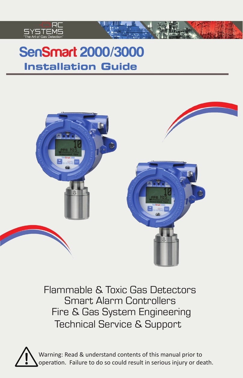
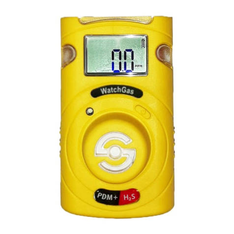
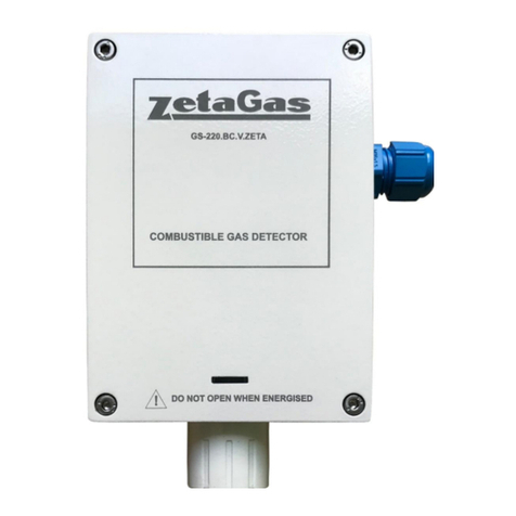
Sens SG-A1 User manual

Research and production
enterprise
SENSOR
Gas Detector
SENS SG-A1
USER MANUAL
SENS.413347.015RE
USER MANUAL, CONFIGURATION DATA SHEET
OKP 42 1514
FEACN CU 9027 10 100 0

SENS.413347.015RE
2

SENS.413347.015RE
3
TABLE OF CONTENTS
Introduction…………………………………………………………………………………….
4
1 PURPOSE……………………………………………………………………………......
4
2 NAME ……………………………………………………………….……………………..
4
3 TECHNICAL SPECIFICATIONS………………………………………………………
5
4 MARKING…………………………………………………………………………………….
8
5 INFORMATION ABOUT MANUFACTURER…………………………………………….
9
6 COMPLETENESS……………………………………………………………………………
9
7 DESIGN DESCRIPTION, OPERATION PRINCIPLE, PROVISION OF
EXPLOSION PROTECTION……………………………………………………………
9
7.1 Description of design…………………………..................................................
9
7.2 Operation principle…………………………………………………………………
10
7.3 Provision of explosion protection………………………………………………….
12
8 INSTRUCTIONS ON INSTALLATION, COMISSIONING, OPERATION,
MAINTENANCE AND REPAIR…………………………………………………………
13
8.1 Safety measures instructions ……………………………………………………
13
8.2 Operational limitations ………………………………………….........................
13
8.3 Putting product into operation …………………………….………………………
14
8.4 Operational procedure …………………………………………………….…………
18
8.5 Maintenance …………………………………………………………………………
56
8.6 Repair ………………………………………………...................................…..
61
9 TRANSPORTATION AND STORAGE………………………………………………….
62
10 UTILIZATION………………………………………………………………………………
62
11 MANUFACTURER'S
WARRANTY……………..………………………………..…………...........................................
62
Annex A Models of gas detector………………………..………………………………….
63
Annex B. Reference regulatory documents…………………………..……………………
67
Annex C. List of components…………………………………………………………………
69
Annex D. General view, overall and installation dimensions,
security sealing………………………………………………………..
70
Annex E. Models of cable entries……….………………………………………………
71
Annex F. Drawing of explosion protection means…..…………………………..……..
72
Annex G. Checking diagram………………………………………………………………
75
Annex H. Status byte of gas detector……………………………………………………
76
Annex I. Byte of relay configuration………………..………………………………….
77
Annex J. List of equipment required for maintenance………………………………..
78
Annex K. Commands of HART protocol, list of gas detector parameters……........
79

SENS.413347.015RE
4
This user manual (UM) is designed for studying of device, technical specifications and
operation principle of gas detector SENS SG-A1 (hereinafter referred as gas detector).
UM contains technical data, information on maintenance, methodology for verification
and calibration, as well as other information necessary for correct operation, storage,
transportation and keeping constant operational capability of gas detector.
Gas detector corresponds to requirements of CEHC.413347.015 TU.
Abbreviations and designations used in this User Manual:
SSRS - state standard reference sample;
SENS Line –three-wired line of power and communication for SENS measuring system;
VM - CEHC.413347.010 MP. Gas Detector SENS SG-A. Verification methodology;
LFL - lower flammability limit;
TLV - threshold limit value;
VGM - verification gas mixture;
PT - primary transducer.
1 PURPOSE
1.1 Gas detector is designed for automatic continuous measurement of
underexplosive concentration of combustible gases and vapors, as well as for signaling on
exceeding of specified signaling triggering thresholds.
Gas detector is designed for stationary installation, provides local light indication and
signaling, provides, depending on model, output of information about measured concentration
value using built-in digital indicator, as well as using analogue current output in the form of
unified analog current output signal as per GOST 26.011 and using digital serial interfaces:
- three-wired line of power and communication of measuring system SENS, SENS
protocol;
- RS-485, Modbus protocol;
- HART, HART protocol Revision 6.
Gas detector, depending on the model, provides switching of contacts of two signal
relays when specified threshold of concentration are exceeded or failure occurs.
Models of gas detector are shown in table A.1 of Annex A.
Gas detector may come with cable entries of different models in accordance with figure
E.1 of Annex E.
1.2 Gas detector can be installed at objects in zones of 1 or 2 classes as per GOST
31610.10, in explosion-hazardous zones, with possible appearance of mixtures of combustible
gases and vapors with air - category IIB as per GOST R IEC 60079-20-1, including
temperature group T4 in accordance with GOST 31610.0.
1.3 Range of application - implementation of production control over compliance with
industrial safety requirements, set by legislation of Russian Federation, on operation of
hazardous production object, control of underexplosive concentration of combustible gases.
2 NAME
Name, designation of gas detector, set by Manufacturer and used for purchase order.
«Gas detector SENS SG-A1-I-C3H8-D12» SENS.413347.015 TU.
Gas detector SENS SG-A1 with built-in digital indicator. Interfaces: CEHC, RS-485,
(4...20) mA, HART, relay; calibration gas - propane, cable entries - D12.
«Gas Detector SENS SG-А1-09-CH4-D18-UKBK» SENS.413347.015 TU.
Gas Detector SENS SG-A1. Interfaces: CEHC, (4...20) mA; calibration gas - methane;
cable entries - D18, with armored cable mounting device UKBK.
Note - Interfaces in accordance with Annex A, cable entries in accordance with Annex E.

SENS.413347.015RE
5
3 TECHNICAL PARAMETERS
3.1 Type - stationary, automatic, electric, single-channel continuous action gas detector,
with upper measurement limit of combustible gases and vapors concentration up to 100%
LFL. Gas detector is a self-contained gas analysis instrument.
3.2 Principle of measurement - infrared absorption.
3.3 Sampling method is diffusive.
3.4 Calibration gas propane (C3H8) or methane (CH4), depending on model of gas
detector.
Detectable components:
- combustible gases butane (С4Н10), hexane (С6Н14) for gas detector models with
propane calibration gas;
- combustible gas methane (CH4) for gas detector models with methane calibration gas.
List of components to which gas detector responds, as well as list of undetectable
components is listed in Annex C.
3.5 Operating position - vertical, with primary transducer compartment downwards.
3.6 Operating mode - continuous.
3.7 Gas detector is subject to verification. Time between verifications is two years.
3.8 Operational conditions
3.8.1 Operational conditions are listed in table 3.1.
Table 3.1
Parameter name
Value
Climatic modification as per GOST 15150:
UHL1*, but within temperatures range from
minus 40C to plus 60 C and with upper limit
of relative humidity up to 98 %
Atmospheric pressure, kPa
from 80 to 120
Resistance to sinusoidal vibration effect
as per GOST IEC 60079-29-1-2013
3.8.2 Atmosphere type II as per GOST 15150.
3.8.3 Concentration of mechanical and corrosive admixtures in a controlled medium
should not exceed TLV level in accordance with GOST 12.1.1005.
3.9 Class of human protection against electric shock - 0I as per GOST 12.2.007.0.
3.10 Technical parameters of gas detector are given in table 3.2.

SENS.413347.015RE
6
Table 3.2
Parameter name
Value
Explosion protection marking
1Ex d IIB T4 Gb
DC power supply voltage:
-nominal
9 V
-acceptable
(4,5…30) V*
Power consumption, not more than
2,5 W
Power supply voltage at which failure alarm is activated
(5±0,4) V
Number of configurable alarm signaling thresholds
5
Output signals
SENS Line:
-protocol
SENS
-maximal cross-section of conductors connectable to terminals
2,5 mm²
RS-485 (only for gas detector models with RS-485 interface):
-protocol
Modbus RTU (Slave)
-data rate, Kbit/s
2.4; 4.8; 9.6; 14.4;
19.6; 28.8; 38,4
-number of gas detectors connectable to RS-485 line, not more than
247
-maximal cross-section of conductors connectable to terminals
2,5 mm²
4...20 mA (only for gas detector models with interface 4...20 mA):
-load resistance
(250...500) Ohm
-maximal cross-section of conductors connectable to terminals
2,5 mm²
HART (only for gas detector model with HART interface):
-protocol version
HART Revision 6
Relay (only for gas detector model with relay):
- maximal switchable DC voltage
42 V
- maximal switchable DC voltage (effective value)
30 V
-maximal switchable DC (effective value of AC)
0,5 A

SENS.413347.015RE
7
Cont. of table 3.2
Parameter name
Value
-maximal resistance of closed contacts
0,8 Ohm
-maximal current leakage with 60 V voltage at opened terminals
4 µA
Time of gas detector continuous operation, without null and sensitivity
adjustments, at least
3 months
Self-test duration time after initial power-up, not more than
120 seconds
Protection degree as per GOST 14254
IP66
Mass, kg, not more than
3 kg
*when using CEHC interface, maximal power supply voltage is 18 V.
Metrological specification of gas detector is shown in table 3.3.
Table 3.3
Parameter name
Value
Measurement range for the verification component
(0...100) % of LFL
Time settling for output signal t(90), not more than
60 seconds
Limits of accepted main inaccuracy for measurements:
- absolute within measurement range from 0 to 60% of LFL,
% LFL, not more than
- relative within measurement range over 60 to 100% of LFL, %
LFL, not more than
±3
±5
Output signal variation (), % LFL, not more than
±3
Limits for acceptable additional measurement inaccuracy in case
of temperature variation within ranges:
- (from minis 10 to plus 40) °С, % LFL, not more than
- (from minus 40 to minus 10) °C and (from plus 40 to plus 60)
°C,
% LFL, not more than
±5
±10
Limits of acceptable additional measurement inaccuracy in case
of ambient air pressure variation within range from 80 to 120 kPa
and with pressure variation for each 3.3 kPa, LFL %, not more
than
±1.5
Limits of acceptable additional measurement inaccuracy in case of
ambient relative humidity variation within range from 0 to 98%,
LFL %, not more than
±5
at temperature plus 40 °С and
relative humidity 50 %
3.11 Electrical insulation between all circuits of gas detector and housing must withstand
within 1 minute testing DC voltage with a nominal value of 500 V and frequency (50±5) Hz.
Electrical insulation shall withstand within 1 minute testing DC voltage with a nominal
value of 500 V and frequency (50±5) Hz between:
- circuits "A(D+)", "B(D-)" of RS-485 interface and other circuits of gas detector;
circuits "lout", "lin" of analogue current output and other circuits of gas detector;
circuits "R1", "R2" of each signal relay and other circuits of gas detector.

SENS.413347.015RE
8
3.12 Resistance of insulation between all circuits specified in 3.11, at least:
- 20 MOhm under normal ambient conditions;
- 5 MOhm at maximal value of operational conditions temperature;
- 1 MOhm at maximal value of relative operational conditions humidity.
3.13 Gas detector reliability rates
Mean time between failures with maintenance regulated by this User Manual, at least
15000 hours. Mean time between failures is set for operational conditions specified in table
3.1, for range of operational power supply voltages and maximal length of CEHC line specified
in table 3.2.
The following is considered to be a criterion for failure of gas detector:
- mismatch of metrological indications with ones listed in table 3.3;
- mismatch of power consumption with ones listed in table 3.2;
- mismatch of parameters of built-in technical condition and gas detector failure
indication control means with requirements specified in this user manual.
Assigned lifetime of gas detector - 15 years.
Service life of primary transducer until replacement, in accordance with primary small-
sized transducer Manufacturer documentation.
3.14 Firmware
Gas detector SENS SG-1A has a firmware. Firmware version is shown in table of
configuration parameters table of gas detector Configuration datasheet. Firmware is identified
on demand via digital serial interfaces.
4 MARKING
Marking of gas detector contains:
- Manufacturer's registered trademark (logo);
- name and designation of gas detector;
- year of manufacturing;
serial number of gas detector as per Manufacturer's numbering system;
- explosion protection marking;
- name of certification authority and number of certificate of compliance with requirements
of TR CU 012/2011;
- image of special "Explosion proof" mark;
- Image of single mark for products turnover in the market of the Customs union member-
states;
–warning inscription "ОТКРЫВАТЬ, ОТКЛЮЧИВ ПИТАНИЕ!" (DO NOT OPEN WHEN
ENERGIZED!);
- IP code;
- operational temperatures range;
- marking of conformity to GOST IEC 60079-29-1 «IEC 60079-29-1».
5 INFORMATION ABOUT MANUFACTURER
Manufacturer: NPP SENSOR LLC,
Building 5, Promishlennaya Street, Zarechny, Penza oblast, Russia, 442960
Mailbox: P.O. Box 737, Zarechny, Penza oblast, Russia, 442965
Phone / fax: +7(8412) 652100, service department - +7(8412) 652155.
Webpage: www.nppsensor.ru

SENS.413347.015RE
9
6 COMPLETENESS
Completeness of gas detector is shown in table 6.1
Table 6.1
Name
Designation
Quantity
Gas Detector SENS SG-A1.
CEHC.413347.015-XX.XX
1 pcs
User Manual
SENS.413347.015RE
1 copy*
Configuration data sheet
CEHC.426456.005PS
1 copy
Verification method
SENS.413347.010MP
1 copy**
Magnetic key
SENS.301111.020
1 pcs
Plug
SENS.713141.203
1 pcs
Ring 024-027-19-2
GOST 9833-73
1 pcs
Packing rings
for D12 cable entry
SENS.754177.041-01
2 sets.
SENS.754177.041-02
Accessories
adapter for supplying of VGM to gas detector
SENS.301536.048
1 copy**
*for a batch delivered to one address; additional copies are available on customer's request;
**supplied with separate purchase order.
7 DESIGN DESCRIPTION, OPERATION PRINCIPLE, PROVISION OF EXPLOSION
PROTECTION
7.1 Description of design
General view, overall and installation dimensions of gas detector are shown in figure 1 of
Annex D.
Gas detector consists of housing (1) with compartment for installation of PT (2) and two
cable entries (3) cover (4), electronic unit (5). Electronic unit is mounted in the housing using
captive screws (6). Housing has tails (7) for mounting of gas detector. Grounding clamp (8)
designed for connection of grounding conductor is located on the housing. On the cover tail
there is a stopper screw (21) preventing it from unscrewing.
The face panel of gas detector contains:
- "FAILURE" indicator;
- "THRESHOLD" indicator;
- "POWER" indicator;
- three-digit digital indicator "% LFL" (only for gas detector models with built-in digital
indicator);
- area of magnetic key exposure for resetting of alarm locking signaling (9).
Tightness of gas detector is provided by design of its housing and use of rubber packing
rings located in cable entries.
Electrical connection of gas detector to external circuits is performed using screw
terminal clamps located on the electronic unit and accessible after removing of housing top
cover and extraction of electronic unit.
Electronic unit contains screw terminal clamps:
- «4…20 mA HART» (10), for connection of circuits of analogue current output (4…20)
mA HART;
- «SENS» (11), for connection of circuits of SENS interface line or power supply circuits
of gas detector models -00…-18;
- «RS-485» (12), for connection of circuits of RS-485 interface;
- "Relay 1" (13), for connection of circuits switched by signal relay 1;

SENS.413347.015RE
10
- "Relay 2" (14), for connection of circuits switched by signal relay 2.
Screw terminal clamp "4...20 mA" contains circuits:
- "lin", for load connection (current flowing in);
- "lout", for load connection ((current flowing out).
Screw terminal clamp "SENS" contains circuits:
- "+", for connection of positive power supply conductor;
- "L", for connection of signal conductor of SENS line;
- "-", for connection of common (negative) power supply conductor.
Screw terminal clamp "RS-485" contains circuits:
- "B", for connection of B (D-) signal conductor of RS-485 cable;
- "A", for connection of A (D+) signal conductor of RS-485 cable;
- "Com" for connection of "Common' conductor of RS-485 cable.
Electronic unit contains "SENSOR" (15) connector for connection of PT cable.
Primary transducer (16) is located in compartment for PT installation. The compartment
is covered with protective cap (20). And is fixed by stopper screw 22 from self-unscrewing.
7.2 Operation principle
7.2.1 Principle of Gas Detector operation is based on the absorption of radiation in the
infrared specter part by the detectable gases and subsequent transformation of the measured
concentration of gas or vapor into a digital output signal. With passage of infrared radiation
through the analyzed medium, radiation is partly absorbed, which leads to change of optic
sensor signal in proportion to amount of gas or vapors.
7.2.2 Gas detector operates in automatic mode when power is supplied, in accordance
with specified configuration parameters.
Gas detector performs measurement of concentration and forms output analog unified
current signal 4...20 mA which is proportional to the measured concentration (only gas
detector models with interface 4...20 mA). Upon request from devices performing display and
processing of information, gas detector transmits digital signal HART to "current loop" line,
which corresponds to measured value of concentration (only gas detector models with HART
interface).
Upon request from devices performing display and processing of information, gas
detector transmits digital signal to RS-485 line, which corresponds to measured value of
concentration (only gas detector models with RS-485 interface).
Upon request from devices performing display and processing of information, gas
detector transmits digital signal to SENS line, which corresponds to measured value of
concentration (only gas detector models with SENS interface).
Gas detector implements output of information about measured value of concentration
using built-in digital indicator (only gas detector models with built-in digital indicator).
When specified threshold value of gases or vapors concentration is exceeded, a
corresponding bit is set in the status byte of gas detector in accordance with Annex H. Status
byte is transmitted by gas detector to the SENS line, received and analyzed by other devices:
switching units, power and switching units (BK and BPK type), light, sound signaling devices
(VS type), multichannel signaling devices (MS-K, VS-K type), which use the fact of change or
existence of specified bit, in accordance with their settings, to switch circuits of actuating
devices, turning on or off light and/or sound signaling.
Gas detector provides switching of contacts of two signal relays in case of specified
concentration exceeding, initiation of failure or other events (only gas detector models with
relay).
7.2.3 Gas detector at the installation location, using indicators on face panel, provides
light indication and signaling:

SENS.413347.015RE
11
- value of measured concentration (only gas detector models with built-in digital
indicator);
- error code in accordance with table 8.5 (only gas detector models with built-in digital
indicator);
- availability of power supply voltage;
- exceeding of measurement range;
- operation mode - special;
- alarm, in case of specified concentration thresholds exceeding;
- failure, in cases:
- reducing of gas detector power supply voltage below specified level;
- loss of connection with primary transducer;
- negative results of self-test.
Note - Special mode - self-test, verification, emulation mode, error occurrence, power
supply voltage drop below normal.
"FAILURE" indicator with yellow glowing color indicates failures of gas detector, results of
self-test or exceeding of measurement range.
Operation modes of "FAILURE" indicator:
-no glow - no gas detector failures, positive results of self-test;
- constant glow - failure - no connection with primary transducer or negative results of
self-test;
- rapid interrupted glow (glow and pause durations are approximately equal to 0,5 s) -
failure - power supply voltage below normal;
-interrupted glow (three glow pulses, then 1.5 s pause, repeated) - exceeding of
measurement range (100% LFL by verification component).
"THRESHOLD" indicator with red glowing color informs the operator about exceeding of
gas or vapors concentration thresholds specified for alarm signaling.
Operation modes of "THRESHOLD" indicator:
- no glow - value of concentration is below specified thresholds for alarm signaling;
- interrupted glow - value of concentration above specified threshold of alarm non-locking
signaling;
- constant glow - value of concentration above specified threshold of alarm locking
signaling.
"POWER" indicator with green glowing color informs the operator about availability of
electric power supply and operation mode of gas detector.
Operation modes of "POWER" indicator:
- no glow - no power supply of gas detector;
- constant glow - power is supplied to gas detector;
- interrupted glow - gas detector is in special operation mode.
Interrupted simultaneous synchronous glowing of all indicators (glow and pause durations
are approximately equal to 1 s) means that gas detector is in self-test mode or checking
indication devices operational capability.
Reset of gas detector is performed by touching of exposure area on the face panel with
magnetic key. Thus a return of gas detector to initial state is performed, after triggering of alarm
locking signaling.
7.3 Provision of explosion protection
Gas detector is explosion-proof equipment, complies with requirements of GOST
31610.0, GOST IEC 60079-1, and GOST IEC 60079-29-1, and has «flameproof enclosure» d
«type of explosion protection. Explosion protection marking of gas detector «1Ex dIIB T4
Gb».

SENS.413347.015RE
12
Type of explosion protection "flameproof enclosure "d" is achieved by housing of
electrical circuits into flameproof enclosure which has a high degree of mechanical strength,
withstands pressure of explosion and eliminates transfer of explosion into explosive area.
Drawing of explosion protection means for explosion protection type "flameproof
enclosure "d" is shown in figure F.1 of Annex F.
Couplings of parts providing "d" type of explosion protection are shown on drawing of
explosion protection means and marked with "EXPLOSION" word.
Explosion-proof feature and tightness of cable entry is achieved by strong compression
of outer cable insulation by packing ring (5) (figure E.1 of Annex E) along its whole length
threaded bushing (4) must be screwed with force specified in figure E.1 of Annex E.For
connection of gas detector a cable with round cross-section is applied, with outer diameter:
(5…8) mm, (8…10) mm, (10…12) mm, (12…14) mm, (14…16) mm, (16…18) mm. Depending
on outer diameter of applied cable, a corresponding packing ring (5) is applied. Packing ring
has marking corresponding to diameter of clamped cable:
- for D12 cable entry: «5-8», «8-10», «10-12»;
- for D18 cable entry: «12-14», «14-16», «16-18».
Housing of gas detector has external grounding clamp. Grounding clamp is secured
against self-unscrewing by application of spring washer and manufactured in accordance with
GOST 21330.
Maximal temperature of outer surface corresponds to temperature class T4.
Gas detector marking includes warning inscription "ОТКРЫВАТЬ, ОТКЛЮЧИВ
ПИТАНИЕ" (DO NOT OPEN WHEN ENERGIZED).
8 INSTRUCTIONS ON INSTALLATION, COMMISSIONING, OPERATION,
MAINTENANCE AND REPAIR
8.1 Safety measures instructions
8.1.1 Installation, commissioning, operation, maintenance and repair of the valves shall
be performed in accordance with requirements of:
GOST 31610.17;
GOST 31610.19;
GOST IEC 60079-29-2.
as well as other acting regulatory documents regulating requirements for provision of fire and
explosion safety, safety measures, ecological safety on organization and operation of electrical
installations.
8.1.2 Only persons who studied User Manual and documents listed in article 8.1.1 as well as
given proper instructions are allowed to install, operate, do maintenance and repair.
8.1.3 Installation and deinstallation shall be only performed with power supply disconnected.
8.1.4 Ingress of moisture inside cable entries is not allowed during installation.
8.1.5 Grounding shall be performed in accordance with the requirements of regulatory
documents using grounding devices shown on drawing.
8.1.6 When working with cylinders containing pressurized verification gas mixtures, it is
necessary to observe safety requirements in accordance with Federal rules and regulations
document "Rules of industrial safety of hazardous production facilities that use equipment working
under excess pressure", approved by the order of Rostechnadzor dated 25.03.2014, No.116.
8.1.7 It is not allowed to discharge VGM in the atmosphere of working premises during
maintenance of gas detector.
8.2 Operational limitations
Operation of gas detector is not allowed when:
- it has mechanical damages;

SENS.413347.015RE
13
- media are corrosive to the materials of housing;
- power supply voltage mismatching;
- ambient air temperature and humidity not corresponding to operational conditions;
- explosion protection means inappropriate.
During operation, gas detector should be protected from shocks, drops, vibration exposure. It
is prohibited to paint parts of gas detector. It is prohibited to subject gas detector to exposure of
high temperatures and metal spray when welding.
It is not recommended to place gas detector in atmosphere of saturated vapors of petroleum
products for more than 4 hours. When exposed to vapors of petroleum products with concentrations
200% LFL or more, zero recovery time may increase significantly.
When designing system that use SENS SG-A1 gas detector within SI SENS, please consider
the following. Performance of SENS system is determined by time of response (T) of actuating
mechanisms, signaling devices to reaching of specified threshold values by parameters of
measured medium (by concentration) or to occurrence of other events, such as switching of gas
detector to special mode, initiation of failure or exceeding of measurement range.
The response time is determined by number of SENS devices in SENS line and is calculated
using the formula:
T = (600 + 72 • D + 191 • S + 560 • A) ms,
where D - number of sensors (gas detectors SENS SG-A1, level gauges, temperature sensors
SENS PT, pressure sensors SENS PD, etc.);
S - number of displaying instruments (signaling devices MS-K-500-...);
A - number of adapters (LIN-RS232, LIN-RS485, LIN-USB and etc.).
Note - Specified value of T is maximal, real response time - 0...T. Number of signaling
devices is considered to be equal to one, regardless of their number in SENS line, if signaling
devices are configured for "hibernation" mode.
If calculated T time it too large, then to reduce it, apply multiple separated from each
other SENS lines.
Example. SENS system has two gas detectors SENS SG-A1, one multi-channel
signaling device MS-K-500-3 and one adapter LIN-USB. Time T is determined using formula
and is equal to:
T = (600 + 72 • 2 + 191 • 1 + 560 • 1) = 1495 ms ≈ 1.5 s.
8.3 Putting product into operation
8.3.1 In case of big temperature difference between storage conditions and operational
conditions, gas detector received from the warehouse shall be held in operational conditions
for at least four hours.
8.3.2 After prolonged storage or transportation in wet conditions gas detector shall be
dried in normal conditions for at least eight hours.
8.3.3 Before installation of gas detector, carefully read this user manual, perform visual
inspection and check for marking, cable entries fittings, housing integrity, terminal for
connection of external circuits.
8.3.4 The gas detector shall be visually inspected before installation and beginning of
operation. Please draw your attention to:
- absence of mechanical damages, state of protective varnish-and-paint and
electroplated coatings;
- completeness of device according to User Manual;
- absence of detachable or loosely fastened elements;
- marking of explosion protection, warning inscriptions;

SENS.413347.015RE
14
- availability of cable entry and cover packing means in accordance with explosion
protection means drawing;
- availability of marks on product acceptance in "Certificate of acceptance" section of
this user manual.
It is prohibited to handle gas detector with damages of outer enclosure, cables,
grounding circuit, with missing plate of explosion protection marking.
8.3.5 Checking of operational capability
8.3.5.1 Assemble checking circuit in accordance with figure 8.1. To access screw
terminal clamps of gas detector electronic unit, perform actions specified in 8.3.6.4.
ATTENTION! CHECKING OF GAS DETECTOR OPERATIONAL CAPABILITY MUST
BE PERFORMED OUTSIDE OF EXPLOSIVE AREA.
8.3.5.2 During checking atmosphere in place of gas detector installation shall not contain
flammable gases or vapors.
Iin Iout
“4...20 mA/
HART”
“Relay 1” “Relay 2”
+ L
“SENS”
-
“RS485”
BАCom
+
-
DC power supply unit
Upit –9V for models -00…-18
МS-K-500-3
+
-
L
R1 1±5% kOhm
B
ARS485-USB
Interface converter USB
Signaling device
R2 220±5% Ohm
Measuring
resistance coil
P331 (100 Ohm)
Multimeter Agilent
34401A in DC voltage
measurement mode
only for gas detector models with RS485 interface
to PC
only for gas detector model with analogue current output
HART
modem
only for gas detector model
with HART interface
USB
to PC
only for gas detector
models with relay
Gas Detector
Ohmmeter 2
Ohmmeter 1
only for gas detector models with SENS interface
For gas detector models -00…-18 positive conductor of power supply unit is
connected to “+” circuit of “SENS” screw terminal clamp of electronic unit,
negative conductor of power supply unit is connected to “-” circuit of “SENS”
screw terminal clamp of electronic unit.
Figure 8.1

SENS.413347.015RE
15
8.3.5.3 Supply power to checking circuit. Within approximately 60 s after supply of
power voltage gas detector remains in self-test mode. At the same time on the front panel of
instrument there should be interrupted synchronous glowing of all indicators (glowing and
pause durations are approximately equal to 1 s). Err is displayed on display of signaling
device MS-K-500-3 during this time, current in the 4...20 mA interface circuit is equal to
3.5±0.2 mA, Modbus holding register with 0 address is set to zero (see table 8.7), data
transmitted over HART: primary variable (Concentration, % LFL) is equal to 0xFFFFFFFF
(value of primary variable is equal to "NAN" in "Configuration of HART Gas Detectors" PC
program); secondary variable (value of current in line 4...20 mA) is equal to 3,5 mA.
Note - Current in 4...20 mA interface circuit, depending on indications of voltmeter
connected in parallel to measuring resistance coil, is calculated using formula shown in notes
below.
After self-test procedure, in case of failures absence and positive results of test, gas
detector is switched to measurement mode.
At the same time, indicators on face panel must be in the following state:
"THRESHOLD" - no glow;
"FAILURE" - no glow;
"POWER" - constant glow;
- indicator "% LFL% displays concentration value (only gas detector models with built-in
digital indicator).
After stabilization, indications read using all available interfaces, must be within
inaccuracy range determined by specifications of gas detector.
Note - Nominal static function of gas detector conversion using DC output signal I, mA, is
as follows: I = IN+ Kn• (CD- CN),
where: IN- lower threshold of DC output signal range, equal to 4 mA;
CD- actual value of verification component concentration in % LFL;
CN- lower limit of measurement range equal to 0% LFL;
Kn- nominal coefficient of conversion mA/% LFL, calculated using formula:
NV
NV
пCC II
K
where: IV, IN- upper and lower thresholds of DC output signal range, equal to 20 mA and 4
mA respectively;
СV, СN- upper and lower limits of measurement range equal to 100% LFL and 0% LFL
respectively.
Indications of gas detector via analogue current output (C, % LFL) are determined in
accordance with diagram shown in figure 8.1, as per formula:
н
nks
ksizmks C
КRUU
C
0.
where: Kn- nominal coefficient of conversion mA/% LFL;
UKS.IZM - voltage drop measure on the measurement resistance coil, mV;
UKS0 - voltage drop at measurement resistant coil corresponding to current INand equal
to 400 mV;
RKS - nominal resistance of measurement resistance coil equal to 100 Ohm.
8.3.5.4 Perform checking of operational capability for relay 1 and relay 2 in accordance
with 8.5.3.3. To control state of relay contacts, use ohmmeter 1 and ohmmeter 2.
8.3.5.5 It is recommended to check zero calibration and sensitivity of gas detector in
accordance with 8.5.3.4 and 8.5.3.5.

SENS.413347.015RE
16
8.3.5.6 Configure gas detector in accordance with specific application as per subsection
8.4. Configuration of gas detector may be performed by Manufacturer in accordance with
customer requirements. At the same time, it is necessary to check correspondence of
configuration parameters, listed in configuration data sheet of gas detector, to specific
application and, if necessary, correct them in accordance with subsection 8.4
Note - It is necessary to draw attention to correct setting of gas detector address in
SENS system (for gas detector model with SENS interface) and in RS-485 Modbus protocol
network (for gas detector model with RS-485 interface), as installation of gas detector with
same addresses in one segment of SENS line and one segment of RS-485 Modbus protocol
network is not allowed.
8.3.5.7 For cases if composition of atmosphere includes combustible gases or vapors,
check of gas detector is performed using VGM No.1 (high purity nitrogen, grade 1, with volume
fraction of nitrogen, %, at least 99.999 as per GOST 9293) and VGM adapter, in accordance
with check diagram shown in figure G.1 of Annex G as follows:
- supply VGM No.1 to gas detector, using rotameter, set flow rate of VGM 0.4 to 0.6
l/min;
- perform operations as per 8.3.5.3, 8.3.5.4;
- stop supply of VGM No.1 to gas detector;
- perform actions as per 8.3.5.5.
8.3.5.8 Turn off power supply, disassemble checking circuit.
8.3.6 Installation
8.3.6.1 Before installation
8.3.6.2 Selection of installation place
Selection of installation place should be performed in accordance with GOST IEC 60079-
29-2-2013, explosion protection marking and requirements of actual regulatory documents,
depending on application object.
Gas detector must be installed vertically, with compartment for primary transducer
downwards.
Do not install gas detector in places where elements of product design may be exposed
to damaging mechanical impacts.
It is required to install gas detector in place with access for maintenance.
8.3.6.3 Mounting of gas detector
Gas detector is mounted on the flat surface using bolts (pins) and housing tails (7) (see
figure D.1 of Annex D).
8.3.6.4 Wiring and sealing
Loosen stopper screw (21), remove cover (4). Remove two captive screws (6), remove
electronic unit (5) from gas detector housing. For convenience of wiring, disconnect cable of
PT from "SENSOR" connector (15).
ATTENTION! FOR WIRING USE ROUND-SECTION CABLE WITH OUTER DIAMETER:
- for D12 cable entry: 5-8, 8-10, 10-12 mm;
- for D18 cable entry: 12-14, 14-16, 16-18 mm.
Connection and sealing of gas detector shall be performed by following methodology in
accordance with figure E.1 of Annex E:
- remove bushing (4), remove plug (1) designed for sealing of gas detector during
storage and transportation. Insert cable that has a length sufficient for connection to screw
terminal clamp of electronic unit, into housing of device.
Note - tighten bushing (4) in unused cable entry for strong compression of the plug (1).

SENS.413347.015RE
17
- remove outer cable sheath for 20 ... 30 mm, remove wire conductors insulation for 4 to
6 mm;
- consequently put on the cable threaded bushing (4), push-bushing (3) and packing ring
(5). Connect stripped ends of conductors for screw terminal clamp, in accordance with marking
shown in figure 8.1.
ATTENTION! PACKING RING (5) SHALL COMPRESS OUTER CABLE INSULATION
ALONG FULL LENGTH OF THE RING. MARKING OF PACKING RING (5) MUST MATCH
CABLE DIAMETER!
- install threaded bushing (4) with torque shown in figure E.1 of Annex E. Cable must not
shift or turn in the rubber packing.
Install electronic unit into the housing of gas detector, tighten two captive screws, install
cover, and then fix cover with stopper screw.
Grounding of gas detector shall be performed in accordance with requirements of
regulatory documents. External grounding clamp (5) is designed for it (figure D.1 of Annex D).
Clamp includes bolt, flat and spring washers.
To prevent unauthorized access, gas detector can be protected by security seal. Security
sealing procedure is shown in figure D.1 of Annex D.
8.4 Operational procedure
8.4.1 General information
Operation of gas detector mainly includes viewing of parameters controlled by
transducer, inputting of data necessary for its operation and configuring of its parameters.
Output of information on measured concentration is performed:
- using three-digit digital indicator for gas detector model with built-in digital indicator;
- via digital interface of SENS line (SENS protocol) for gas detector model with SENS
interface;
- via digital interface RS-485 (Modbus protocol) for gas detector model with RS-485
interface;
- via digital interface HART (HART Revision 6 protocol) for gas detector model with
HART interface;
- via analogue current output 4...20 mA as per GOST 26.011-80 for gas detector model
with analogue current output;
Input of data required for operation and configuration of gas detector parameters can be
performed via digital interface of SENS line (for gas detector model with SENS interface), via
digital interface RS-485 (for gas detector model with RS-485 interface), via digital interface
HART (for gas detector model with HART interface).
List of critical failures of gas detector is shown in table 8.1.
Table 8.1.
Failure description
Cause
Actions
Gas detector is not
operable
Mismatching power
supply voltage
Check and bring into accordance.
Gas detector supply and
(or) control circuits open.
Tighten cable wires in terminal
clamps of gas detector. Comply
with requirements of 8.3.6.4.
Required functions are
not provided.
Mismatching technical
parameters.
Incorrect gas detector
connection, open or
short control circuits.
Bring into accordance with
application diagram, figure 8.1.
Incorrect configuration
Bring into accordance with 8.4

SENS.413347.015RE
18
Failure description
Cause
Actions
(programming)
Unknown
Please consult service department
of the Manufacturer
List of possible personnel (user) mistakes causing emergency operation mode of
equipment and actions to prevent specified mistakes are given in table 8.2.
Table 8.2.
Mistake description,
personnel actions
Possible consequences
Actions
Incorrect attachment of
cover or cable entry, or
incorrect assembly (or
missing) of cable entry
parts of gas detector.
Required level of explosion
protection is not provided.
Inflammation and medium
explosion in explosive area
is possible.
Disconnect power supply and
solve non-conformity.
Ingress of water into cavity of
cable entry or housing.
Failure of device and
automation system provided
by it, for example, forced
ventilation system. As a
result, initiation of explosive
atmosphere, ignition,
explosion and fire are
possible.
1. In case of early detection: turn
off gas detector power supply,
dry cavity of cable entry to the
complete removal of moisture.
2. In case of late detection
(imitation of corrosion, presence
of water on clamps, changing
structure of parts material
surface), gas detector has to be
repaired by Manufacturer.
8.4.2 Operation of gas detector via digital interface of SENS line (SENS protocol).
8.4.2.1 General information
Operation of gas detector is performed mainly using multi-channel signaling devices MS-
K-500-3 or PC with the use of adapters LIN-RS232, LIN-USB and corresponding software.
Detailed description of MS-K-500-3 signaling device operation procedure is given in its
user manual.
Gas detector operation via PC is provided by "ARM SI SENS" program, and configuration
program is "Configuration of sensors and secondary devices". Detailed description of
operation procedure using a PC and software is given in the corresponding user manuals.
Following instruction is operation procedure using multi-channel signaling device MS-K-
500-3.
Gas detector operation is performed by buttons of MS-K-500-3 signaling device;
corresponding information is displayed on the instrument indication board. During operation,
short-press (duration less than 1 second) and long-press of buttons are distinguished.
In operation mode during viewing of parameters, transition from one parameter to
another is performed by short-press of right-button of MS-K-500-3 signaling device, and
transition to viewing of parameters of the next SI SENS device is performed by short- or long-
press of the left button.

SENS.413347.015RE
19
Interface between gas detector and signaling device MS-K-500-3 is organized in a menu.
Composition of menu items differs depending on operator's access rights. There are two levels
of operator's access - "user" and "administrator" (change parameters mode).
"User" access level mode is designed for viewing of displayed concentration, as well as
configuration parameters.
"Administrator" access level mode is designed for viewing of displayed concentration, as
well as for changing of configuration parameters.
Quick-access menu and configuration menu of gas detector is available for each of levels
(see below).
Menu scrolling is performed as follows:
Current menu item is displayed on the display of signaling device. Moving to next or
previous menu item is performed by short-press of right or left button respectively. Selection of
current menu item (enter) is performed by short-press of the right button.
Quick exit from menu (current menu item) without saving changes is performed by
simultaneous pressing of the left and right buttons.
Exit from menu (current menu item) is performed as follows:
Short-press right button several times to scroll to menu item or subitem End. if any
changes were made in the selected menu subitems, then short-press of the right-button shows
a request on the display –SAV? (save?). Long-press of the right button is used for save and
exit changes, the display consequently shows messages –YES, SAVE (yes, saved). Short-
press or no press of right button is used for exit without saving changes, the display shows
message –no (not saved).
Typing of address and other digital parameters is performed as follows:
When inputting numeric parameter, current digit order is flashing. To scroll between digit
orders, short-press left or right button respectively. When inputting fractional numeric values,
short-press of left button with flashing highest figure is used to move to input the position of
separator of the integer and fractional parts –dot, this dot starts to flash.
Long-press of left or right button performs scrolling between digit order values, ascending
or descending respectively, as well as changes position of separator between integer and
fractional parts. Typing of negative numbers is performed by selection of "-" sign for extreme
highest figure.
Entering of the typed numeric value is performed by short-press of the right button with
extreme smallest figure.
Selection menu item parameter is performed as follows:
Current value of selected parameter is flashing on the display. Scrolling of parameters
values, forward or backwards, is made by long-press of left or right button. Selection (input) of
the current value parameter is made by short-press of the right button.
8.4.2.2 Viewing parameters
Composition of displayed parameters depends on the access rights.
Parameters which can be set for displaying in operating mode:
- Cn - Concentration, % LFL. Concentration of components which is used for
measurement and signaling. Parameter is available for displaying both for user and
administrator;
- CH - Concentration, %, volumetric fraction. Concentration value, sent by PT for
verification component without any intermediate mathematical conversions. Parameter is
available for displaying only for administrator. CH parameter is used for zero setting and
calibration of sensitivity during maintenance, verification of gas detector, as well as in
emulation mode.
8.4.2.3 Quick-access menu
Structure of quick-access menu is shown in figure 8.2.

SENS.413347.015RE
20
Set.u CH
User
settings
Enter quick-access menu (USEr)
End
Hold
End
Exit to operation mode of viewing parameters
Cn bt EndСН
Viewing parameters
in hold mode
Figure 8.2
Entering quick-access menu from operation mode of viewing parameters is performed by
long-press of right button of multi-channel signaling device MS-K-500-3. The display will
shows menu designation USEr and first quick-access menu item SEt.u.
Quick-access menu contains items:
-SEt.u - User settings. Item is available only for administrator and displayed in emulation
mode (see below). Item contains subitem CH - Concentration, %, vol. fraction - initial value of
concentration entered by operator;
-Hold - Viewing parameters in hold mode. Fast hold and viewing of values of all
measured or calculated parameters corresponding to last measurement. Contains subitems:
- CH - Concentration, %, volumetric fraction.
In measurement mode - value of concentration sent by PT for verification component. In
emulation mode - initial value of concentration entered by operator in accordance with item
SEt.u.
- Cn - Concentration, % LFL. Calculated value of component concentration which is used
for measurement and signaling.
-bt - Bits. Status byte of gas detector in accordance with Annex H.
Status byte of gas detector is only displayed with administrator access level mode.
8.4.2.4 Menu of gas detector configuration
Structure of gas detector configuration menu is shown in figure 8.3.
Table of contents
