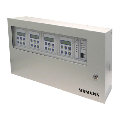
Siemens Water Technologies Series User manual

ACUTEC™35
GAS DETECTION
SYSTEM
BOOK NO. WT.050.130.000.UA.IM.1108

WT.050.130.000.UA.IM.1108
ACUTEC™ 35 SYSTEM
EQUIPMENTSERIALNO._____________________________
DATEOFSTART-UP________________________________
START-UPBY____________________________________
Prompt service available from nationwide authorized service contractors.
ORDERING INFORMATION
In order for us to fill your order immediately and correctly, please order material by description and part number, as shown
in this book. Also, please specify the serial number of the equipment on which the parts will be installed.
WARRANTY
Seller warrants for a period of one year after shipment that the equipment or material of its manufacture is free from defects
in workmanship and materials. Corrosion or other decomposition by chemical action is specifically excluded as a defect
covered hereunder, except this exclusion shall not apply to chlorination equipment. Seller does not warrant (a) damage
causedbyuseofthe items forpurposes other than those forwhichtheywere designed, (b) damage caused by unauthorized
attachments or modifications, (c) products subject to any abuse, misuse, negligence or accident, (d) products where parts
not made, supplied, or approved by Seller are used and in the sole judgement of the Seller such use affects the products’
performance, stability or reliability, and (e) products that have been altered or repaired in a manner in which, in the sole
judgementofSeller,affects theproducts’performance,stabilityorreliability.SELLER MAKES NO OTHER WARRANTY OF
ANY KIND, AND THE FOREGOING WARRANTY IS IN LIEU OF ALL OTHER WARRANTIES, EXPRESS OR IMPLIED,
INCLUDING ANY WARRANTY OF MERCHANTABILITY OR OF FITNESS OF THE MATERIAL OR EQUIPMENT FOR
ANY PARTICULAR PURPOSE EVEN IF THAT PURPOSE IS KNOWN TO SELLER. If Buyer discovers a defect in mate-
rial or workmanship, it must promptly notify Seller in writing; Seller reserves the right to require the return of such defective
parts to Seller, transportation charges prepaid, to verify such defect before this warranty is applicable. In no event shall
such notification be received by Seller later than 13 months after the date of shipment. No action for breach of warranty
shall be brought more than 15 months after the date of shipment of the equipment or material.
LIMITATION OF BUYER’S REMEDIES. The EXCLUSIVE REMEDY for any breach of warranty is the replacement f.o.b.
shipping point of the defective part or parts of the material or equipment. Any equipment or material repaired or replaced
under warranty shall carry the balance of the original warranty period, or a minimum of three months. Seller shall not be
liable for any liquidated, special, incidental or consequential damages, including without limitation, loss of profits, loss of
savings or revenue, loss of use of the material or equipment or any associated material or equipment, the cost of substitute
material or equipment, claims of third parties, damage to property, or goodwill, whether based upon breach of warranty,
breach of contract, negligence, strict tort, or any other legal theory; provided, however, that such limitation shall not apply
to claims for personal injury.
Statements and instructions set forth herein are based upon the best information and practices known to Siemens Water
Technologies Corp., but it should not be assumed that every acceptable safety procedure is contained herein. Of necessity
this company cannot guarantee that actions in accordance with such statements and instructions will result in the complete
elimination of hazards and it assumes no liability for accidents that may occur.
1.010-42
Water Technologies
1901 West Garden Road, Vineland, NJ 08360
s

WT.050.130.000.UA.IM.1108
ACUTEC™ 35 SYSTEM
Introd.
INTRODUCTION
TheSiemens Water TechnologiesSeries 50-130Acutec™35Gas Detec-
tionsystemisanon-linemonitoringsystemforthedetectionofchlorine
(Cl2), sulfur dioxide (SO2), or ammonia (NH3) gas in ambient air. Alarm
contacts are provided to transfer at user selectable setpoints. Monitor
modules provide a digital readout of gas level and a 4-20 mA output.
Single or Dual Units are available, using any combination of gas detec-
tors and monitors or alarm units.
OneReceiverModuleisconnectedtoeachgasSensor/Transmitterwitha
two-conductorcable,andprovidesinformationonthegasconcentration
in the sensor area. Receivers are powered by the Power Supply Module
supplied with the Gas Detector system.
TheSeries50-130Sensor/Transmitterconsistsofanelectrochemicalgas
sensor and an electronic amplifier that transmits a gas concentration
signal to a Receiver Module located in the Control Unit. An optional gas
generator may be ordered which enables the Receiver to automatically
test the sensor every 24 hours.
NOTE:Whenorderingmaterialalwaysspecifymodelandserialnum-
ber of apparatus.
Table Of Contents
Very Important Safety Precautions .......................... SP-1,-2
Regional Offices ..................................................... 1.010-1
Technical Data........................................................ Section 1
Installation............................................................. Section 2
Operation............................................................... Section 3
Service................................................................... Section 4
Parts Illustrations.................................................... Section 5
Spare Parts List....................................................... Section 6

ACUTEC™ 35 SYSTEM
WT.050.130.000.UA.IM.1108 SP-1
VERY IMPORTANT SAFETY PRECAUTIONS
Thispagetitled“VeryImportantSafetyPrecautions”provides,inbrief,informationofurgentimportance
relative to safety in the installation, operation, and maintenance of this equipment.
WARNING
TO AVOID POSSIBLE SEVERE PERSONAL INJURY AND EQUIPMENT DAMAGE, OBSERVE THE FOLLOWING
PRECAUTIONS:
GASES DETECTED ARE HAZARDOUS SUBSTANCES, AND IF BREATHED IN HIGH CONCENTRATIONS CAN
CAUSE DEATH. THE OPERATION OF THIS DETECTOR MUST BE CHECKED AND VERIFIED FREQUENTLY ON
A REGULAR SCHEDULE.
TO AVOID INJURY FROM ELECTRICAL SHOCK, TURN POWER SOURCES OFF BEFORE SERVICING EQUIPMENT.
TO AVOID POSSIBLE SEVERE PERSONAL INJURY OR DAMAGE TO EQUIPMENT, THIS PRODUCT SHOULD
ONLY BE USED WITH POWER SUPPLIES THAT HAVE A SINGLE HOT WIRE WITH RESPECT TO EARTH. THE
WIRE CONNECTED TO POWER SUPPLY TERMINAL “N” MUST BE NEUTRAL. POWER AND EARTH GROUND
MUST BE PROPERLY CONNECTED AS SHOWN.
THE GENERAL SENSOR RESPONSE TEST, AS DESCRIBED IN THIS MANUAL, MUST BE PERFORMED WHEN-
EVER A NEW SENSOR IS INSTALLED.
AFTER ANY MAINTENANCE THE DETECTOR SHOULD BE TESTED FOR RESPONSE TO ASSURE NORMAL
OPERATION.
REPLACE SENSOR IMMEDIATELY IF SENSOR FAILS GAS TEST.
HANDLE BATTERIES WITH CARE, BEING CERTAIN NOT TO SHORT TERMINALS, AS SEVERE ARCING OR
EXPLOSION COULD OCCUR.
TO ENSURE PROPER AND SAFE OPERATION OF THIS EQUIPMENT, USE ONLY SIEMENS WATER TECH-
NOLOGIES LISTED PARTS EXCEPT COMMERCIALLY AVAILABLE PARTS AS IDENTIFIED BY COMPLETE
DESCRIPTION ON PARTS LIST. THE USE OF UNLISTED PARTS CAN RESULT IN EQUIPMENT MALFUNC-
TIONS CAUSING POSSIBLE SEVERE PERSONAL INJURY.
THIS EQUIPMENT SHOULD BE INSTALLED, OPERATED AND SERVICED ONLY BY TRAINED, QUALIFIED
PERSONNEL WHO ARE THOROUGHLY FAMILIAR WITH THE ENTIRE CONTENTS OF THIS INSTRUCTION
BOOK.

ACUTEC™ 35 SYSTEM
WT.050.130.000.UA.IM.1108 SP-2
VERY IMPORTANT SAFETY PRECAUTIONS (CONT’D)
DO NOT DISCARD THIS INSTRUCTION BOOK UPON COMPLETION OF INSTALLATION. INFORMATION
PROVIDED IS ESSENTIAL TO PROPER AND SAFE OPERATION AND MAINTENANCE.
ADDITIONAL OR REPLACEMENT COPIES OF THIS INSTRUCTION BOOK ARE AVAILABLE FROM:
Siemens Water Technologies Corp.
1901 West Garden Road
Vineland, New Jersey 08360
Phone: (856) 507-9000
Fax: (856) 507-4125
NOTE
Minorpartnumberchangesmaybe incorporatedintoSiemensWaterTechnologiesproductsfromtime
totimethatarenotimmediatelyreflectedintheinstructionbook.Ifsuchachangeapparentlyhasbeen
made in your equipment and does not appear to be reflected in your instruction book, contact your
local Siemens Water Technologies sales office for information.
Please include the equipment serial number in all correspondence. It is essential for effective commu-
nication and proper equipment identification.

WT.050.130.000.UA.IM.1108
ACUTEC™ 35 SYSTEM
REGIONAL OFFICES
INSTALLATION, OPERATION, MAINTENANCE, AND SERVICE INFORMATION
Direct any questions concerning this equipment that are not answered in the instruction book to the
Reseller from whom the equipment was purchased. If the equipment was purchased directly from
Siemens Water Technologies Corp., Vineland, NJ, contact the office indicated below.
UNITED STATES
1901 West Garden Road
Vineland, NJ 08360
TEL: (856) 507-9000
FAX: (856) 507-4125
CANADA
If the equipment was purchased directly from Siemens Water Technologies Canada, Inc., contact the
nearest office indicated below.
ONTARIO QUEBEC
250 Royal Crest Court 243 Blvd. Brien
Markham, Ontario Bureau 210
L3R3S1 Repentigny, Quebec
(905) 944-2800 (450) 582-4266
1.010-1

WT.050.130.000.UA.IM.1108
ACUTEC™35 SYSTEM
1
SECTION 1 – TECHNICAL DATA
List Of Contents
PARA./DWG. NO.
Technical Data........................................................ 1.1
Interferences.......................................................... 1.2

WT.050.130.000.UA.IM.1108
ACUTEC™35 SYSTEM
2
1.1 Technical Data
Gas Ranges
Gas Standard
Range Minimum
Range Maximum
Range
Chlorine 0 - 10 ppm 0 - 5 ppm 0 - 50 ppm
Sulfur Dioxide 0 - 20 ppm 0 - 10 ppm 0 - 100 ppm
Ammonia 0 - 100 ppm 0 - 50 ppm 0 - 500 ppm
Gas sensors are shipped factory set to standard ranges, but may be
calibrated to other ranges as shown.
Setpoints Adjustable, 5 - 100% of Range
Enclosure Ratings NEMA4X (except battery enclosure)
Distance, Transmitter to Receiver 1000 ft. (maximum)
Operating Temperature 0 to 105 °F, continuous
-10 to 120 °C, intermittent
Humidity 0 - 99%, non-condensing
Power 85 - 255 VAC, 50/60 Hz, 15 W
Contacts Alarm (configurable): 3 SPDT
Trouble: 1 SPDT
Power Failure: 1 SPDT
Contact Rating 10 A at 120 VAC, 5 A at 250 VAC,
Resistive
Battery Back-up (optional) 12 V, 4 A/hr, 6 Hrs minimum
Analog Output (optional) 4-20 mA, Isolated, 1000 ohms
maximum
Sensor Life 2 years (maximum)
Gas Generator Life 1 year
NOTE: The Auto-Test option is for indoor use only, and should only
be used with detectors set to the standard range or lower, as shown
in the GAS RANGES table. If used with higher ranges, the generator
may not produce enough gas to test the sensor.

WT.050.130.000.UA.IM.1108
ACUTEC™35 SYSTEM
3
1.2 Interferences
Electrochemical sensors are, by nature, not 100% selective; therefore,
they can exhibit response to other gases present in ambient air.
The following tables list the possible interferences that may occur when
usingthedifferent gassensors. The tablesindicatetherelative response
of the sensor to 1 ppm of the listed gas, expressed in terms of relative
ppm signal. For example: exposure of a chlorine sensor to a gas sample
containing1ppmofnitrogendioxide(NO2)wouldproduceasignalequal
to 0.4 ppm of chlorine. A negative sign (-) indicates an interference that
can cause low gas measurements if there is a mixture of the measured
gas and another gas.
CHLORINE
Interference Gas Response
Bromine 1.0
Fluorine 1.0
Chlorine Dioxide 1.0
Ozone 1.0
Nitrogen Dioxide 0.4
Hydrogen Sulfide -0.1
Hydrogen Cyanide -0.05
Methyl Mercaptan -0.04
Sulfur Dioxide -0.01
SULFUR DIOXIDE
Interference Gas Response
Nitrogen Dioxide 0.8
Hydrogen Cyanide 0.15
Nitric Oxide 0.04
Acetylene 0.02
Ethanol 0.05
Hydrogen 0.005
Bromine -0.1
Fluorine -0.1
Chlorine Dioxide -0.1
Ozone -0.1

WT.050.130.000.UA.IM.1108
ACUTEC™35 SYSTEM
4
AMMONIA
Interference Gas Response
Methyl Mercaptan 7
Hydrogen Sulfide 2
Hydrogen 0.1
Nitrogen Dioxide -0.2
Chlorine -0.2

WT.050.130.000.UA.IM.1108
ACUTEC™35 SYSTEM
5
SECTION 2 – INSTALLATION
List Of Contents
PARA./DWG. NO.
Overview................................................................ 2.1
General Installation ................................................ 2.2
Mounting Power Supply and Receiver Modules........ 2.3
Electrical Connections............................................. 2.4
Installation of Power Supply Module....................... 2.5
Illustrations
Dimensions
Single Point Detection System.............................. 50.130.100.001
Dual Point Detection System ................................ 50.130.100.002
Sensor/Transmitter............................................... 50.130.100.003
Battery Back-up.................................................... 50.130.100.004
Installation Wiring
Single Point Detection System........................... 50.130.130.001
Dual Point Detection System ............................. 50.130.130.002

WT.050.130.000.UA.IM.1108
ACUTEC™35 SYSTEM
6
2.1 Overview
The Series 50-130 Gas Detection System consists of modular com-
ponents that can be used in a variety of configurations to fit specific
application requirements. Following is a brief description of the
major system components. More detailed information follows later
in this manual.
• BASE UNIT: Includes a Power Supply Module housed in a NEMA 4X
enclosure.Single-PointUnitsacceptsoneReceiverModule,andDual-
Point Units accept two Receiver Modules. All units are provided with
an audible horn.
• POWER SUPPLY MODULE: Provides power for one or two Receiver
Modules, for the audible horn, and for charging an external Battery
Back-up. The power supply accepts 85 to 255 volts, ac (50/60 Hz)
and mounts on a DIN rail.
• DETECTOR RECEIVER MODULE: Receives a signal from a one Sensor/
Transmitter, canbe set fortwoalarmlevelsandprovides three alarm
contacts. The Receiver Module mounts on a standard DIN rail. Re-
ceiver Modules include a Reset/Acknowledge button, provide power
for Sensor/Transmitters, and control Autotest Generators.
• MONITORRECEIVERMODULE:SameastheDetectorModule,butalso
includes a digital display of gas level and a 4-20 mA output.
• SENSOR/TRANSMITTER:Consistsofanelectrochemicalgassensorcon-
nected to a NEMA 4X transmitter, which sends a signal to a Receiver
Module.
• AUTOTEST GENERATOR: An electrochemical gas generator which
attaches to Sensor/Transmitters and automatically tests sensor
response daily.
NOTE: The Auto-Test option is for indoor use only, and should only
be used with detectors set to the standard range or lower, as shown
in Section 1.1 – Technical Data. If used with higher ranges, the gen-
erator may not produce enough gas to test the sensor.
• BATTERY BACK-UP: The Battery Back-up option for gas detection sys-
tems consists of a separate wall-mounted enclosure which houses a
battery and a control circuit board. The battery is a sealed, lead-acid
type and is rated four ampere-hours.

WT.050.130.000.UA.IM.1108
ACUTEC™35 SYSTEM
7
2.2 General Installation
NOTE: Power supply or Receiver modules may be shipped with pro-
tective transparent plastic covers. These covers should be peeled
off and discarded.
System enclosures, Battery Back-up units, and Sensor/Transmitters are
alldesignedforsurfacemountingusingscrewsorboltsinsertedthrough
therecessedmountingholesateachcorneroftheenclosures.Mounting
hole dimensions are shown on the appropriate diagram. Included with
each system enclosure are mounting hole templates which can be used
to mark hole centers on walls or mounting panels. Mounting recesses
are suitable for #8 machine screws or wood screws.
Referto paragraph3.4.1, Sensor Installation,forspecificinformationon
locating gas sensors.
Enclosures are supplied with conduit hubs and seal rings for water-tight
connection of 1/2” NPT threaded conduit. Plastic cable glands may also
be purchased to connect cables without conduit.
Install the 1/2” conduit hubs in any enclosure knockout labeled PG16.
Note that some knockouts have more than one designation, such as
PG11/16. Those with two designations will have concentric circles
for knockouts. The inner circle marks the lower PG number while the
outer circle marks the higher number. Place a thin bladed screwdriver
intothe circularslotorthedesiredknockoutsizeandtap firmly witha
hammer (see Figure 2.1). Place the seal over the hub threads on the
outside of the enclosure and attach the hub with the supplied nut.
Figure 2.1
The Acutec™ unit should not be exposed to direct sunlight. Continuous
ambient temperature should not exceed 105 °F. When this temperature
is likely to be approached, it is recommended that relays be used in the
non-energizedmode,andthedisplaybesettonormalintensity(Monitor
Units only). See Section 3 for details.

WT.050.130.000.UA.IM.1108
ACUTEC™35 SYSTEM
8
2.3 Mounting Power Supply and Receiver Modules (See Dwg. 50.130.000.001)
Power Supply and Receiver Modules are mounted to a standard 35 x 7.5
mm DIN rail in the detection system enclosure. The spring loaded clip
with the loop holds the module to the rail. To install modules, first slide
the bottom of the module under the rail. Then pull the loop out with a
small screwdriver while lowering the top of the module onto the rail. To
remove modules, reverse this procedure.
2.4 Electrical Connections (See Dwgs. 50.130.130.001 And 50.130.130.002)
Field wiring required for the Detection System includes connection of
ac power, connection of two-conductor cable between the Receiver and
the Sensor/Transmitter, connection of the Battery Back-up unit (when
purchased), and connection of the audible horn to Receiver Modules. A
25-footlengthoftwo-conductor cable is supplied foreachSensor/Trans-
mitter. Longer lengths of up to 1000 feet may be used when required.
Theacinputpower is connectedtothelower leftof the PowerModule,
as shown in the Installation Wiring drawings. A ground terminal is pro-
vided on the mounting track for connection of earth ground. For safe
operation and to avoid noise interference, it is important that earth
ground be connectedtothis terminalfirst, and then tothepower input
earth ground terminal on the Power Supply Module, as shown.
WARNING: TO AVOID POSSIBLE SEVERE PERSONAL INJURY OR DAM-
AGE TO EQUIPMENT, THIS PRODUCT SHOULD ONLY BE USED WITH
POWER SUPPLIES THAT HAVE A SINGLE HOT WIRE WITH RESPECT TO
EARTH. THE WIRE CONNECTED TO POWER SUPPLY TERMINAL “N”
MUSTBENEUTRAL.POWERANDEARTHGROUNDMUSTBEPROPERLY
CONNECTED AS SHOWN.
NOTE: Field wiring must conform to local electrical codes.
The wiring drawings show internal wiring of the systems. Sensor/Trans-
mitter connections are shown in paragraph 3.4.1, Sensor Installation.
All terminal blocks are plug-in type, and can be unplugged allowing re-
placement of modules without removing individual wires.
Electrical connection is made between the Battery Back-up unit and
the Power Supply Module. The circuit board mounted on the battery
contains a two-position plug-in terminal block marked plus and minus.
The plus terminal is connected to terminal B+ of the power supply and
the minus terminal is connected to B- of the power supply.
!

WT.050.130.000.UA.IM.1108
ACUTEC™35 SYSTEM
9
2.5 Installation of Power Supply Module
The Power Supply Module used in the gas detection system operates
on ac supplies of 85 volts to 255 volts, at 50/60 Hz. No adjustments or
modifications are required of the user.

WT.050.130.000.UA.IM.1108
ACUTEC™35 SYSTEM
10
NOTE: ( ) INDICATES DIMENSIONS IN MILLIMETERS.
SINGLE POINT DETECTION SYSTEM - DIMENSIONS
50.130.100.001
ISSUE 3 8-08
7-3/16”
(183)
6-9/16”
(167)
4-5/16”
(110)
7-1/16”
(179) 6-1/2”
(165)
s

WT.050.130.000.UA.IM.1108
ACUTEC™35 SYSTEM
11
NOTE: ( ) INDICATES DIMENSIONS IN MILLIMETERS.
DUAL POINT DETECTION SYSTEM - DIMENSIONS
50.130.100.002
ISSUE 3 8-08
9-7/16”
(240)
10”
(254) 4-3/8”
(111)
7-1/16”
(179) 6-1/2”
(165)
s

WT.050.130.000.UA.IM.1108
ACUTEC™35 SYSTEM
12
NOTE: ( ) INDICATES DIMENSIONS IN MILLIMETERS.
A ACCESSORY ITEM FURNISHED ONLY IF SPECIFICALLY LISTED IN QUOTATION.
WHEN THE GAS GENERATOR IS USED, THE UNIT MUST BE MOUNTED AS SHOWN.
SENSOR/TRANSMITTER - DIMENSIONS
With Generator
50.130.100.003
ISSUE 2 7-98
3-3/4”
(95)
3-1/8”
(79)
3-3/4”
(95)
1-1/8”
(29)
1-1/16”
(27)
3-1/8”
(79)
2-5/8”
(67)
1-3/8”
(35)
3/4”
(19)
2-1/4”
(57)

WT.050.130.000.UA.IM.1108
ACUTEC™35 SYSTEM
13
NOTE: ( ) INDICATES DIMENSIONS IN MILLIMETERS.
BATTERY BACK-UP - DIMENSIONS
50.130.100.004
ISSUE 2 7-98
4-3/8”
(111)
3-3/4”
(95)
3-1/2”
(89)
7-1/8”
(181)
6-1/2”
(165)

WT.050.130.000.UA.IM.1108
ACUTEC™35 SYSTEM
14
SINGLE POINT DETECTION SYSTEM - INSTALLATION WIRING
50.130.130.001
ISSUE 2 11-08
NOTE: SWIRING BY SIEMENS WATER TECHNOLOGIES.
FIELD WIRING MUST CONFIRM TO LOCAL ELECTRICAL CODES.
This manual suits for next models
1
Table of contents
Other Siemens Gas Detector manuals