sauermann SGTP-CO User manual

USER MANUAL
SGTP-CO
CARBON MONOXIDE DETECTOR

User manual
2

User manual
3
Table of Contents
1Description........................................................................................................................................................4
2Warning............................................................................................................................................................4
3Caution.............................................................................................................................................................5
4Product overview ...............................................................................................................................................6
5Activation & deactivation....................................................................................................................................7
6Mode................................................................................................................................................................8
6.1 Measuring mode........................................................................................................................................8
6.2 Display mode.............................................................................................................................................8
6.3 Alarm Activation & Setting Alarm set points.................................................................................................8
7Event log...........................................................................................................................................................9
8Calibration ........................................................................................................................................................9
8.1 Fresh air calibration....................................................................................................................................9
8.2 Remaining calibration day.........................................................................................................................10
8.3 Standard gas calibration...........................................................................................................................10
8.4 Return to measuring mode.......................................................................................................................11
8.5 Calibration gas concentration ...................................................................................................................11
9Tests...............................................................................................................................................................12
9.1 Self test...................................................................................................................................................12
9.2 Bump Test...............................................................................................................................................12
10 Sensor and battery replacement ....................................................................................................................13
10.1 Sensor replacement..................................................................................................................................13
10.2 Battery replacement .................................................................................................................................13
11 Specifications ..............................................................................................................................................14
12 Certificates..................................................................................................................................................15
13 Limited Warranty .........................................................................................................................................15

User manual
4
1Description
SGTP-CO is a portable single gas detector designed to detect the presence of CO gas in the ambient
environment. SGTP-CO has a replaceable gas sensor and battery, giving an unlimited lifetime of operation.
When activated, SGTP-CO continuously monitors ambient air for the presence of carbon monoxide (CO)
and alerts the user to potentially unsafe exposure with LED, vibrating, and audible alarms in the event that
gas concentration exceeds alarm set points.
The SGTP-CO is designed for use in hazardous areas and offers reliable and durable monitoring in a
compact, lightweight package. It is also designed to withstand the harshest industrial working conditions
and is simple to operate.
2Warning
Any unauthorized attempt to repair or modify the product, or any other cause of damage beyond the
range of the intended use, including damage by fire, lightening, or other hazard, voids liability of the
manufacturer
Activate this product only if sensor, visual, detection, and audible cover are clear from contaminants
such as dirt and debris that could block the area where gas is to be detected.
Do not clean and rub the LCD screen of the products with a dry cloth or hands in hazardous
environment to prevent the static electricity.
Perform cleaning and maintenance of the products in fresh air that is free of hazardous gases.
Test the response of a sensor regularly by the gas concentration exceeding alarm set point
Test LED, audio and vibration manually.
Gas concentration measurements by the sensor can vary based on the environment (temperature,
pressure and humidity). Therefore, calibration of SGT-P should be performed in the same (or similar)
environment of the device’s actual use.
If the temperature changes sharply during use of the device (e.g., indoors vs outdoors), the value
of the measured gas concentration can suddenly change. Please use the SGT-CO after the gas
concentration value has stabilized.
Severe vibration or shock to the device may cause a sudden reading change. Please use SGT
CO after the value of gas concentration has stabilized. Excessive shock to SGT-P can cause
the device and/or sensor to malfunction
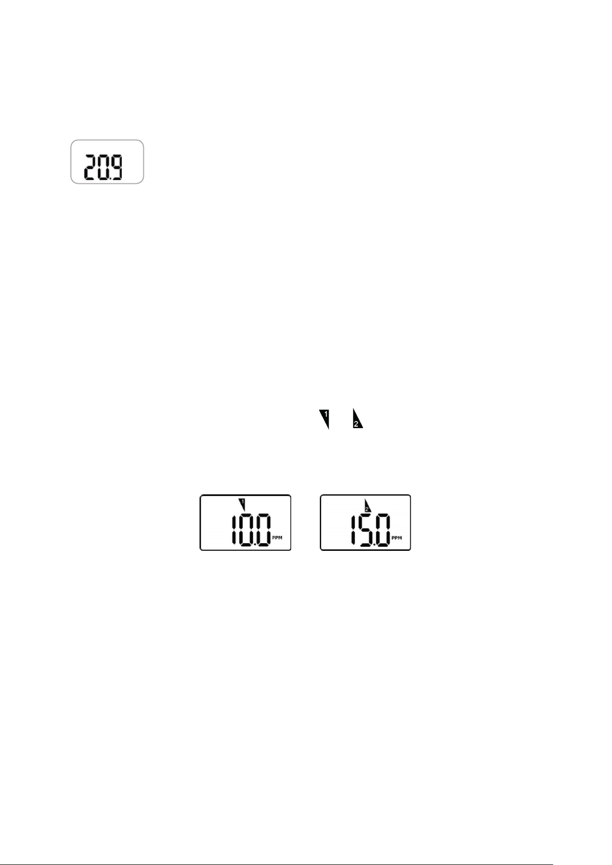
All alarm value is set based on the alarm standard that is required by international standard. Therefore,
alarm values should be changed only under the responsibility and approval of the administration of the
work site where the instrument is used.
Use IR communications in the safety zone which is free of hazardous gases.
Replace the battery and sensor in clean environment, which is free of hazardous gas.

User manual
5
3Caution
Before operating this device, please read the manual carefully.
This device is not a measurement device, but a gas detector.
If calibration and self-test fails continuously, please do not use the device.
Before use, please check the activation date, and if the activation date is past, please do not
use the device.
Clean detectors with a soft cloth and do not use chemical substances for cleaning.
To maintain 24 months lifetime, avoid the below activities except the necessary cases to check
events (Max/Min), lifetime/concentration, and alarm set points. Otherwise, the frequent use of the
button will deplete the battery lifetime less than 24 months.
View a serial number on the label at the back side of the device.

User manual
6
4Product overview
IR port
LCD display
Alarm LED
Buzzer
Button
Gas sensor
Gas type
LCD display symbol
Alarm
Remaining month
Low alarm display
Remaining day
High alarm display
Remaining time (hour)
Stabilization success
Max peak value
Stabilization failure
Min peak value
Fresh air calibration
Measurement unit
Standard gas calibration
Remaining battery life

User manual
7
5Activation & deactivation
In a safe environment, when pressing and holding the button for 3 seconds, gas type and
firmware version (ex. v2.2) will be displayed. For 10 seconds countdown, the device will be
stabilized. After stabilization is completed, “V” icon will appear on the display screen and the
device will move to Measuring.
In the event that stabilization of the device fails, will appear on the display
and Measuring mode will not be entered.
In this case, contact your after-sales service
.
To deactivate the device, pleas press and hold the button for three seconds.
Always ensure that the device makes the proper detection response to the pertinent
gas. Verify that debris that could interfere with the detection of gas are not blocking
the area where gas is to be detected
%Vol

User manual
8
6Mode
6.1 Measuring mode
When activated, in Measuring mode, gas concentration will appear on the screen.
Oxygen concentration is displayed in percent by volume (%Vol) and toxic
concentration is displayed in parts per million. (PPM).
6.2 Display mode
In Measuring Mode, by pressing button for one second, the following ICONs will appear in
order.
MIN. (min value, only for oxygen) →MAX. (max value) →CLR (clear data) →1st alarm set point →
2nd alarm set point →Firmware version →Remaining calibration day →Calibration Concentration
At the last step, if you press button or do not push any button for a second, the device will return to
Measuring Mode.
6.3 Alarm Activation & Setting Alarm set points
When the gas concentration exceeds alarm set points, or will be displayed and the device will
vibrate, flash (LED), and beep. To remove alarms, move to a clean air location. and then a gas concentration
will decrease, and alarm will stop.
To set the alarm setpoints, please follow the steps below:
-Press the button until the above alarm setpoint is displayed.
-Press and hold the button for three seconds and the first digit of alarm setpoint starts to
blink.
-To increase the value, press the button for one second.
-To save the alarm setpoints, press the button for 3 seconds.
*Ensure that the second alarm set point must be greater than first alarm setpoint.
* Ensure Standard Factory alarm set points vary depending on countries, states, and
companies. Before changing alarm setpoints, please ensure the alarm set points are in
compliance with your local guidelines.
%Vol

User manual
9
7Event log
Last 30 events are stored on a device. Once more than 30 events are stored, the log events are removed
automatically in the order starting at Event 1.
Each alarm event records followings: Types of alarms (1st or 2nd) / Alarm concentration in ppm or % / Peak
concentration
8Calibration
Initial calibration is performed on all devices prior to shipment. Once received,
calibration should be performed monthly (or quarterly) depending on frequency of use.
Measuring mode
Fresh air calibration Standard gas calibration
8.1 Fresh air calibration
When pressing and holding the button for 5 seconds in the calibration mode, ( ), icon and “CAL”
mark will appear on the LCD. And, press the button to initiate calibration for three seconds. When
calibration begins, a countdown (starting at 10) will appear on the screen.
Once completed, icon will appear on the LCD.
If calibration fails, icon will appear on the display.
If this continues, please contact the distributor of the device or the after-sales service.
%Vol
%Vol
%Vol
%Vol
%Vol

User manual
10
8.2 Remaining calibration day
Initial setting. The default day will be 180 days.
To check the remaining day, press the button until the above image is displayed.
Calibration should be performed in a fresh-air environment that is free for any influence
of other gases (since calibration is assumed to be performed in an environment with
20.9% of Oxygen). It is also recommended that calibration should be performed in a
space that is not confined.
8.3 Standard gas calibration
When pressing and holding the button for 5 seconds in the calibration mode , icon and ‘CAL’
mark will appear, and when pressing button once again, icon will appear. And then, press and hold the
button for three second to initiate calibration. When calibration begins, a countdown (60 seconds or more
depending on sensor types) will appear on the
Once completed, icon will appear several seconds on the display. Then, the device will return to
Measuring mode.
Once calibration fails, icon will appear on the display.
If this continues, please contact your distributor.
%Vol
%Vol
%Vol
%Vol
%Vol

User manual
11
8.4 Return to measuring mode
In the standard calibration mode , by pressing the button for a second, the fresh air calibration,
standard calibration, and ESC will appear on the display consecutively. In the ESC mode, press the
button for 3 seconds, the device will be get out of the calibration mode. And press the button one time,
it will return Measuring mode.
8.5 Calibration gas concentration
Gas
Concentration
CO 100 ppm

User manual
12
9Tests
9.1 Self test
The default of Self-Test is N/A, and the interval is 8hr~20hr, or N/A. To initiate the self-test, please set the
self-test interval via the IR link. After the setting interval is activated, STS message will flash. (The message
will flash until users perform the Self-test.) Once you press the button, it will test buzzer, LED, Vibration,
LCD, 1ST alarm, and 2ND alarm. After the test is completed, END message with icon will be displayed.
(Users are required to check the test processes manually.)
9.2 Bump Test
The interval of Bump-test is 1~365days, and the default is N/A. To initiate the bump test, set the bump test
interval. Once the bump test time reaches, bts message will flash. Once you press and hold the button for 3
seconds, the tst message will be displayed for 45 seconds (To cancel, press the button for one second).
Within the 45 seconds, apply a test gas (If no gases are applied, the bts message will flash again). After the
selected gas is applied, if the test is successful, SUC message with will be displayed after 30 seconds.
And then, remove the calibration cap and gas tube. If the
test fails, FA message with will be displayed and bts message will be flashing until the test is
successful.
PPM
PPM

User manual
13
10 Sensor and battery replacement
1. It is absolutely prohibited to replace battery at potential explosion or dangerous
regions. Replace the battery in a clean environment, which has no hazardous gases.
2. Replacement of components can invalidate the intrinsic safety function. It is
recommended to have the sensor and the battery changed by an authorised technical
centre.
3. Replace sensors and batteries with manufacturer-approved components. Battery
brand: Vitzrocell, Co.Ltd, model Tekcell (SB-AA02 3.6V)
4. Disassembly should be necessary only for sensors & battery replacement. After the
sensor re-placement, the span gas calibration should be done.
5. Before disassembling, please turn off the power and remove screws.
10.1Sensor replacement
1. Deactivate the detector
2. Remove the 6 screws on the back case.
3. Remove the 2 screws on the PCB board.
4. After removing the battery, replace with the new sensor matching with the gas type. For instance, If you
have the SGT-P CO, the CO sensor should be used for the replace-ment.
5. Assemble the detector.
6. After assembling, perform the fresh air calibration and standard calibration with the concentration in this
manual.
7. Have the sensor stabilized for 5 minutes before use.
10.2Battery replacement
1. Deactivate the detector
2. Remove the 6 screws on the back case.
3. Replace with the new battery.
4. Assemble the detector.
5. After assembling, perform the fresh and standard calibration.
6. Before use, have the sensor stabilized for 5 minutes

User manual
14
11 Specifications
Model SGTP-CO
Gas CO
Measuring range 0 - 500 ppm
Sensor type Electrochemical cell
Measurement Diffusion
Display LCD screen
Alarm Audible alarm, 90 dB at 10 cm, Red Flashing LEDs, vibration alarm
Event log Recent 30 alarms
Battery Manufacturer: Vitzrocell / P/N: SB-AA02(P) / System: Lithium Primary
Battery Nominal voltage: 3.6V / Nominal capacity:
1.2Ah
Operating
temperature
From -40 to +50 °C
Relative humidity 5 – 95 % RH (non-condensing)
Housing
Rubber Enclosure
IP 67
Operating life 24 months, based on 2 minutes of alarm per day
Size 54 mm (W) x 91 mm (H) x 32 mm (D)
Weight
93 g
Approval
Ex ia IIC T4 Ga
ATEX, Korea Ex, IECEx, CSA & UL, INMETRO

User manual
15
12 Certificates
Intrinsic Safety
The detector is in conformity of the following standards
IECEx : Ex ia II C T4 Ga IECEx KTL 19.0019X
ATEX : 2198 II 1 G Ex ia IIC T4 Ga IP67
KRH 19 ATEX 1022X
Directive 2014/34/EU
KCS: Ex ia IIC T4
KTL 19-KA2BO-0491X
Compliance: Electromagnetic Compatibility Directive 2014/30/EU
Manufacturing Approval: The detector manufacturer is certified compliant with ISO 9001:2000 provisions
Standards:
The electrical apparatus and any acceptable variations to it specified in the schedule of this certificate and
the identified documents, was found to comply with the following standards:
• IEC 60079-0: 2011 Ed. 6
• IEC 60079-11: 2011 Ed 6
• UL 61010-1, Ed. 3
• UL 913, Ed. 8
• UL 60079-0, Ed. 6
• UL 60079-11, Ed. 6
• C22.2 No. 60079-0:2015
• C22.2 No. 60079-11:2014
• C22.2 No. 61010-1-12:2012
• EN 60079-0: 2012+A11:2013
• EN 60079-11: 2012
13 Limited Warranty
This product is free from defects in materials and workmanship under normal use for a period of 2 years
from the date of purchase.
The manufacturer is not liable (under this warranty) if its testing and examination disclose that the alleged
defect in the product does not exist or was caused by the purchaser’s (or any third party’s) misuse, neglect,
or improper installation, testing, or calibrations. Any unauthorized attempt to repair or modify the product,
or any other cause of damage beyond the range of the intended use, including damage by fire, lightening,
water damage or other hazard, voids liability of the manufacturer.
In the event that a product should fail to perform up to manufacturer specifications during the applicable
warranty period, please contact your distributor.
Other manuals for SGTP-CO
2
Table of contents
Other sauermann Gas Detector manuals
Popular Gas Detector manuals by other brands

Perry Electric
Perry Electric 1GA50917MET/P Installation and operating instructions

Crowcon
Crowcon Detective Net Quick reference guide

Alecto
Alecto COA-26 manual

Gas Detection
Gas Detection GDA 3160 operating manual

Sensitron
Sensitron SMART3G-GrI instruction manual

Medem
Medem SEC-K V4 installation instructions