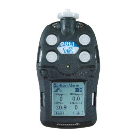
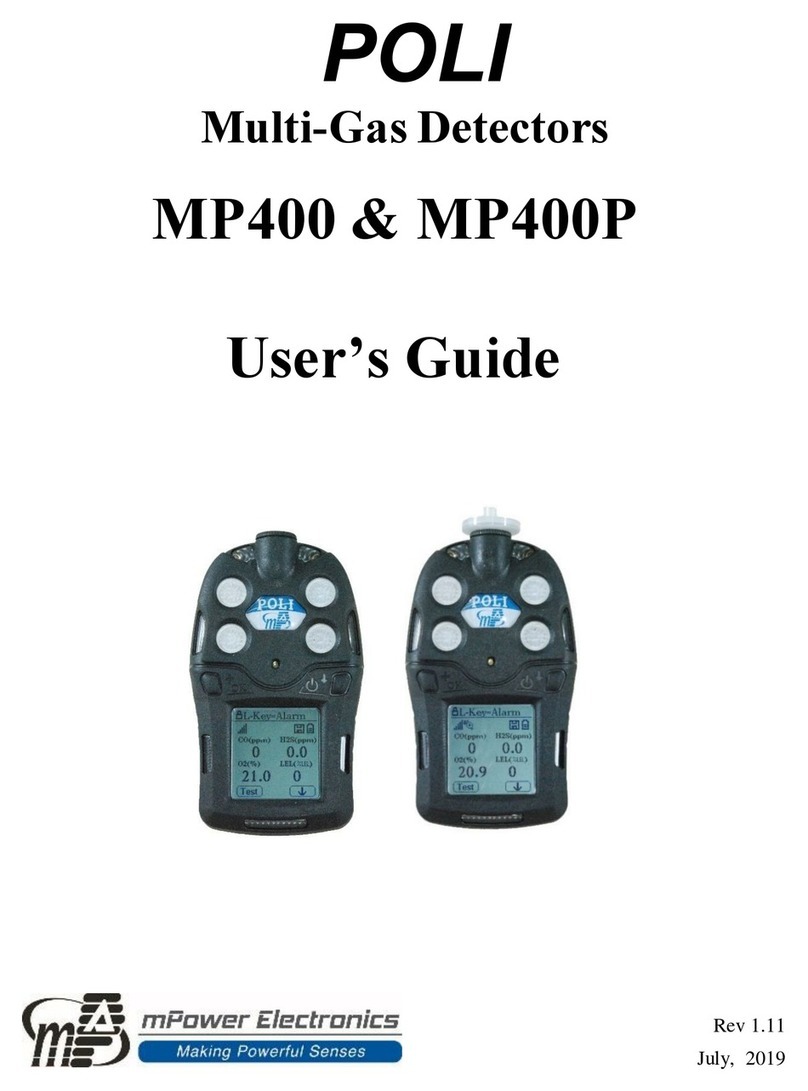
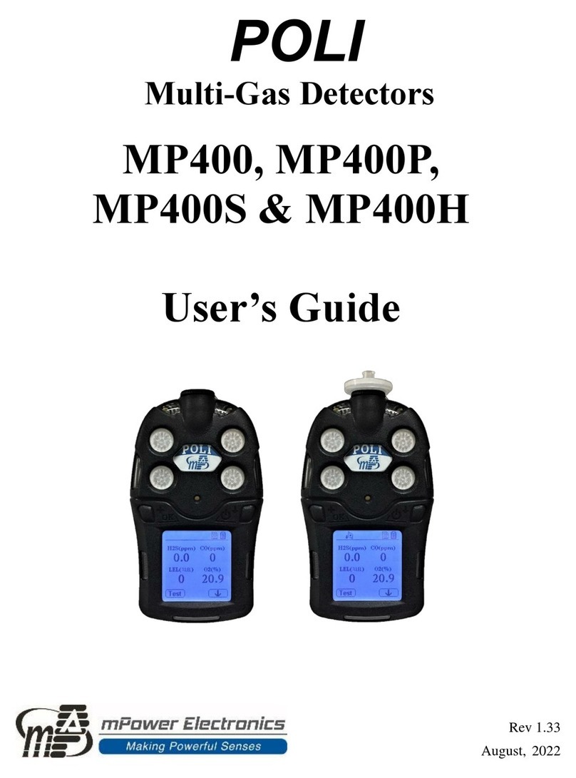
mPower Electronics POLI MP400 User manual

POLI
Multi-Gas Detectors
MP400, 400P & 400S
User’s Guide
Rev 1.0
Dec. 2018

POLI User’s Guide
1
Contents
1. General Information........................................................................................................ 5
1.1 Main Features............................................................................................................ 5
2. User Interface.................................................................................................................. 6
2.1 Displays and Keys..................................................................................................... 6
2.2 Active Sensor Displays............................................................................................. 8
2.3 User Menu................................................................................................................. 9
3. Battery........................................................................................................................... 10
3.1 Replacing A Battery................................................................................................ 10
3.2 Battery Status.......................................................................................................... 10
4. Turning On or Off......................................................................................................... 11
4.1 Turning On.............................................................................................................. 11
4.2 Turning Off............................................................................................................. 11
4.3 Testing Alarm Indicators ........................................................................................ 12
4.4 Pump Status ............................................................................................................ 12
4.5 Calibration Status.................................................................................................... 12
4.6 Bump Status............................................................................................................ 13
5. Config Mode................................................................................................................. 14
5.1 Entering Config Mode ............................................................................................ 14
5.2 Menus and Sub-menus............................................................................................ 15
6. Calibration and Test...................................................................................................... 24
6.1 Manual Alarm Test................................................................................................. 24
6.2 Bump Testing and Calibration................................................................................ 24
7. Data Communication.................................................................................................... 28
8. Maintenance.................................................................................................................. 29
8.1 Replacing Filters..................................................................................................... 29
8.2 Removing/Cleaning/Replacing Sensor Modules.................................................... 29
8.3 Replacing Pumps .................................................................................................... 30
9. Alarm Overview............................................................................................................ 31
9.1 Alarm Signals.......................................................................................................... 31
9.2 Testing Alarms........................................................................................................ 31

POLI User’s Guide
2
10. Troubleshooting.......................................................................................................... 32
11. Technical Specifications............................................................................................. 33
12. Ordering Information.................................................................................................. 37
13. Year of Manufacturing................................................................................................ 38
14. Controlled Part of the Manual for POLI..................................................................... 39
15. POLI Marking............................................................................................................. 41
16. Technical Support and mPower Contacts................................................................... 42

POLI User’s Guide
3
Warning
Read Before Operating
This manual must be carefully read by all individuals who have or will have the
responsibility of using, maintaining or servicing this product. The product will perform as
designed only if it is used, maintained and serviced in accordance with the
manufacturer’s instructions. The user should understand how to set the correct parameters
and interpret the obtained results.
CAUTION!
Remove the monitor cover only in area known as non-hazardous.
CAUTION: HIGH OFF-SCALE READINGS MAY INDICATE AN EXPLOSIVE
CONCENTRATION.
ATTENTION: DES LECTURES SUPÉRIEURES A L’ÉCHELLE PEUVENT INDIQUER
DES CONCENTRATIONS EXPLOSIVES.
WARNINGS
ONLY THE COMBUSTIBLE GAS DETECTION PORTION OF THIS INSTRUMENT
HAS BEEN ASSESSED FOR PERFORMANCE.
UNIQUMENT, LA PORTION POUR DÉTECTOR LES GAZ COMBUSTIBLES DE CET
INSTRUMENT A ÉTÉÉVALUÉE.
CAUTION: BEFORE EACH DAY’S USAGE, SENSITIVITY OF THE COMBUSTIBLE
GAS SENSOR MUST BE TESTED ON A KNOWN CONCENTRATION OF METHANE
GAS EQUIVALENT TO 20 TO 50% OF FULLSCALE CONCENTRATION. ACCURACY
MUST BE WITHIN 0 AND +20% OF ACTUAL. ACCURACY MAY BE CORRECTED
BY CALIBRATION PROCEDURE.
ATTENTION: AVANT CHAQUE UTILISATION JOURNALIERE VERIFIER LA
SENSIBILITE AVEC UNE CONCENTRATION CONNUE DE METHANE
EQUIVALENTE A 20-50% DE LA PLEINE ECHELLE. LA PRECISION DOIT ETRE
COMPRISE ENTRE 0-20% DE LA VALEUR VRAIE ET PEUT ETRE CORRIGEE
PARUNE PROCEDURE D’ETALONNAGE.
Warning: High off-scale readings may indicate an explosive concentration.
Warning: Substitution of components may impact intrinsic safety.
Note: Users are recommended to refer to ISA -RP12.13, Part II-1987 for general
information on installation, operation, and maintenance of combustible gas detection
instruments.

POLI User’s Guide
4
WARNINGS
This device complies with part 15 of the FCC Rules. Operation is subject to the following two
conditions: (1) This device may not cause harmful interference, and (2) this device must accept any
interference received, including interference that may cause undesired operation.
Caution: Changes or modifications to this unit not expressly approved by the party responsible for
compliance could void the user's authority to operate the equipment.
NOTE: This equipment has been tested and found to comply with the limits for a Class B digital
device, pursuant to part 15 of the FCC Rules. These limits are designed to provide reasonable
protection against harmful interference in a residential installation. This equipment generates, uses
and can radiate radio frequency energy and, if not installed and used in accordance with the
instructions, may cause harmful interference to radio communications. However, there is no
guarantee that interference will not occur in a particular installation. If this equipment does cause
harmful interference to radio or television reception, which can be determined by turning the
equipment off and on, the user is encouraged to try to correct the interference by one or more of the
following measures:
—Reorient or relocate the receiving antenna.
—increase the separation between the equipment and receiver.
—Connect the equipment into an outlet on a circuit different from that to which the receiver is
connected.
—Consult the dealer or an experienced radio/TV technician for help.
Proper Product Disposal at The End Of Life
The Waste Electrical and Electronic Equipment (WEEE) directive
(2002/96/EC) is intended to promote recycling of electrical and
electronic equipment and their components at end of life. This symbol
(crossed-out wheeled bin) indicates separate collection of waste
electrical and electronic equipment in the EU countries. This product
may contain one or more Nickel-metal hydride (NiMH), Lithium-ion, or
Alkaline batteries. Specific battery information is given in this user
guide. Batteries must be recycled or disposed of properly. At the end of
its life, this product must undergo separate collection and recycling
from general or household waste. Please use the return and collection
system available in your country for the disposal of this product.

POLI User’s Guide
5
1. General Information
The POLI multi-gas detectors (MP400, 400P & 400S) offer 4 or 5-gas monitoring of
oxygen (O2), combustible (LEL), toxic, carbon dioxide (CO2) gases and volatile organic
vapors (VOCs). The MP400 is a compliance model of O2, LEL, carbon monoxide (CO)
and hydrogen sulfide (H2S) configuration in diffusion. The MP400P is a standard model
and adopts a full range of sensor selection, e.g. electrochemical (EC), pellistor,
non-dispersive infrared (NDIR) and photo-ionization detector (PID) in pump or diffusion.
The MP400S is an advanced model and has a built-in wireless module that sends critical
data of Man Down, Gas and Battery Alarms to supervisors and control centers on site or
at remote locations for faster responses and maximized safety measures.
1.1 Main Features
⚫3 models of diffusion, pump and wireless optimized for compliance, professional and
advanced applications.
⚫Large graphical display icon-driven user interface through intuitive,
simple-to-operate two-button user interface
⚫Over 30 interchangeable sensor configurations, including PID for VOC, NDIR and
catalytic for combustibles, and NDIR for CO2
⚫Intelligent sensors store calibration data ready for installed in the field
⚫Easy access to pump, sensor, filter and battery
⚫Man Down, Gas and Battery Alarm notification via ISM wireless at a free of charge
⚫IP-65/67 water and dust resistant case

POLI User’s Guide
6
2. User Interface
The POLI’s user interface consists of two (2) keys, four (4) sensor sockets, one (1) big
LCD - Liquid Crystal Display, eight (8) alarm LEDs - Light Emitting Diodes, one (1)
buzzer, and two (2) vibration alarms.
2.1 Displays and Keys
The LCD provides visual information that includes real-time gas readings, sensor types,
datalog / battery / pump / wireless status, and others.
Notice information
Man Down alarm on
Valid on calibration & bump test
Datalog status
Battery status
Unit of measure
Indications of left and right key
Reading value
Sensor type
Wireless status
Pump status

POLI User’s Guide
7
2.1.1 Status Indicator Icons
Along the top of most screens are status indicators that tell you whether a function is
operating and/or its strength or level.
Icon
Function
Wireless signal strength at 0-5 level
Pump status (pump version only)
Datalogging status (shown when datalogging is on, blank when off)
Battery voltage status
Man Down alarm enabled
All sensors tested and calibrated tick mark (all sensors have been bump tested and
calibrated; no sensor is overdue for a bump test or calibration according to the
intervals configured on the instrument.
2.1.2 Auto Flip Screen
When positioned up down, the POLI screen is automatically flipped for keeping normal
readings.
2.1.3 Keys and Interfaces
The POLI has two keys:
[+/OK] Key [/↓] Key
Confirm/Number Increase Power/Cursor

POLI User’s Guide
8
Moving
These two keys are marked as [+/OK] and [ /↓] for Confirm or Number Increase and
Power / Cursor Moving, respectively. They also act as ‘soft keys’ that changes numbers
and make selections under various menus.
Two test and symbol boxes at the LCD bottom are ‘mapped to’the [+/OK] and [ /↓]
keys. The text and symbol in the boxes may vary with the menu.
In addition to the functions described above, either key can be used to manually activate
LCD backlighting. Press a key to turn it on when the backlighting is off.
2.2 Active Sensor Displays
Though having four (4) sensor sockets, the POLI is a flexible platform that
accommodates one (1) to five (5) sensors with a dual toxic sensor. When one or more
sensors is either not installed or turned off, the display only shows the installed, active
sensors:

POLI User’s Guide
9
2.3 User Menu
The user menu in the reading mode is simple to go through by pressing the [+/OK] and
[/↓] key.

POLI User’s Guide
10
3. Battery
Always fully charge the battery before using the POLI. Its Li-ion battery is charged by a
Micro-USB cable.
WARNING
To reduce the risk of ignition of hazardous atmospheres, recharge, remove or replace the
battery only in an area known to be non-hazardous!
Plug the mini end of the Micro-USB cable into the charging port of
POLI, and the other end is connected to a USB power adaptor or the
USB port of computer. The screen will display a battery icon from
empty to full. When the battery icon is displayed full grid status
indicating the battery is fully charged.
3.1 Replacing A Battery
The Lithium-ion battery pack inside of the POLI is free of maintenance. In case of a
battery failure or end operating life, please contact mPower service department or
authorized distributors for a battery replacement.
3.2 Battery Status
The battery icon on the display shows how much charge is in the battery, and alerts you if
any charging problem.
blink
Full charge
2/3 charge
1/3 charge
Battery Low
Battery Alarm
When the battery’s charge falls below a preset voltage, the instrument warns you by
beeping once and flashing once every minute. The instrument automatically powers down
within 10 minutes, after which users shall recharge the battery.

POLI User’s Guide
11
4. Turning On or Off
4.1 Turning On
With the instrument turned off, press and hold the [ /↓] Key for 3 seconds, until buzzer
beeps and red LED on, the unit is powered on. It will show informative screens such as:
•Manufacturer’s logo and company name
•Product name, Model No. and Serial No.
•FW version, date, and time
•Battery type, voltage
•Datalog cycle
•Sensor types (High Alarm Limit, Low Alarm Limit, STEL Limit, TWA Limit)
Then the POLI’s main reading screen appears. It usually takes 1 to 2 minutes for sensors
to show meaningful readings. For some sensors not fully warmed up by the time, the
main screen shows ‘- -’instead of numerical values until the sensor is stablized in a few
more minutes typically. Then it displays instantaneous readings similar to the following
screen (depending on the sensors installed) and is ready for use.
Note: If the battery has insufficient power, the LCD briefly shows the message ‘Battery
Fully Discharged’ and the POLI shuts off automatically. You should charge the battery or
replace it with a fully charged battery before turning it on again.
IMPORTANT!
If a major error that prevents the POLI from functioning occurs during startup, the
message ‘Contact Service’ is shown on the display. The instrument should be shut off
and taken to service.
4.2 Turning Off
In normal reading mode, press and hold the [ /↓] Key, the unit will show 5 seconds
count down, with red LED flash and buzzer beeps once per second. After the last long
flash and beep, LCD displays ‘Power Off’, the unit is powered off.
Caution: The alarm is loud. During startup, you can mute most of the sound by
temporarily holding a finger over the buzzer opening hole. Do not put tape over the
buzzer opening as it permanently mutes and causes a serious safety problem.

POLI User’s Guide
12
4.3 Testing Alarm Indicators
Under normal-operation mode and non-alarm conditions, the buzzer, vibration alarm,
LED, and backlight can be tested at any time by pressing [+/OK] once.
IMPORTANT!
If any of the alarms do not respond to this test, check the Alarm Settings in Programming
Mode. It is possible that any or all of the alarms have been turned off. If all of the alarms
are turned on, but one or more of them (buzzer, LED lights, or vibration alarm) does not
respond to this test, do not use the instrument. Contact your mPower distributor for
technical support.
4.4 Pump Status IMPORTANT!
During operation, make sure the probe inlet and the gas outlet are free of obstructions.
Obstructions can cause premature wear on the pump, false readings, or pump stalling.
During normal operation, the pump icon alternately shows inflow and outflow as shown
here:
If there is a pump failure or obstruction that disrupts the pump, the alarm sounds and you
see this icon blinking on and off:
Once the obstruction is removed, you can restart the pump by pressing the [+/OK] key. If
the pump does not restart, and the pump stall alarm continues, consult the
Troubleshooting section of this guide or contact your mPower distributor for technical
support.
Note: Pump status is not indicated on the diffusion POLI.
4.5 Calibration Status
If one or more sensors requires calibration, then the screen shows a highlighted 'CAL'.

POLI User’s Guide
13
Calibration is required if:
•The sensor module has been replaced with one whose calibration is overdue.
•The defined period of time between calibrations has been exceeded.
•Users have changed the calibration gas type without recalibrating the instrument.
•The sensor has failed in a previous calibration.
4.6 Bump Status
If one or more sensors requires a bump test, then the screen displays the word ‘BUMP’ at
the place of the sensor name, and alternates between the sensor name and the word
‘Bump’with a highlighted background:
A bump test is required if the defined period of time between bump tests has been
exceeded. This interval is set by an administrator using mPower Suite software.

POLI User’s Guide
14
5. Config Mode
The menu in Config Mode is to adjust the POLI’s settings and calibrate sensors. It has the
following submenus:
•Sensor: Zero Calib, Span Calib, Bump Test, Span Value, Enable/Disable, Cal Interval,
Bump Interval, Gas Unit.
•Alarm: High Limit, Low Limit, STEL Limit, TWA Limit, Alarm Device.
•Datalog: Interval, Clear All, Log Sensor Sel.
•Unit Setting: Heart Beat Light, Temperature Unit, LCD Contrast, Pump Speed,
Language, Back Light Mode, LCD Auto Rotate, M-Down On/Off, M-Down Timeout,
M-Down Thresh.
•Wireless: Wireless On/Off.
•Exit
5.1 Entering Config Mode
To enter Config Mode, the [+/OK] and [ /↓] together for 3 seconds until you see the
password screen.
The Config Mode is password protected. The default password is ‘0000’. After all four
(4) digits are inputted, press [ /↓] key to enter config mode.
•Increase the number from 0 through 9 by pressing [+/OK].
•Step from digit to digit using [ /↓].
•After inputting the password’s four (4) digits, advance to ‘OK’.
•Press [+/OK] to register the password and enter Config Mode.
If the password input is not correct, you will receive the message ‘Incorrect!’ and the unit
will return to the reading mode automatically.
If the digit input is mistaken, use the [ /↓] key to move cursor among four digits and
press [+/OK] key to change the inputs.
After entering the config mode, the sensor menu is displayed first. Press [ /↓] key to
browse the menu under the config interface.

POLI User’s Guide
15
You can enter one menu, view or edit the parameters in its submenu by pressing [+/OK]
key.
5.2 Menus and Sub-menus
In config mode, menus and submenus are organized as shown here:
Sensor
Alarm
Datalog
Unit Setting
Wireless*
Zero Calib
High Limit
Interval
Heart Beat Light
Wireless On/Off
Span Calib
Low Limit
Clear All
Temperature Unit
Return
Bump Test
STEL Limit
Log Sensor Sel
LCD Contrast
Span Value
TWA Limit
Return
Pump Speed**
Enable/Disable
Alarm Device
Language
Cal Interval
Return
Back Light Mode
Bump Interval
LCD Auto Rotate
Gas Unit
M-Down On/Off
Return
M-Down Timeout
M-Down Thresh
Return
* Wireless version only.
** Pump version only.

POLI User’s Guide
16
5.2.1 Editing Parameters & Selecting Sensors
There are a few basic ways to edit parameters, select sensors, and perform other activities
in the POLI. The actions performed by pressing keys always match 1-to-1 with the boxes
along the LCD bottom and the two keys. Some parameters are edited by scrolling and
selecting individual items (black bars behind white text act as highlighters). Some include
a choice via ‘radio keys’ where only one item in a list can be selected, while other menus
use boxes for you to ‘check’with an ‘X’ and these allow for multiple items in a list to be
selected. In all cases of editing, you can save or undo your choice.
5.2.2 Calibration
Use this menu to perform zero or span calibration for one or more sensors, and change
the gas concentration values equals to that of gas cylinders used in zero or span
calibration.
5.2.2.1 Air (Zero) Calibration
A zero calibration should precede a span calibration.
The selected sensors are shown on the screen. Start a multiple zero test by pressing
[+/OK]. If you do not want to perform a test, press [ /↓].
Zero calibration is to set the base line for the calibration curve, it is done in clean air with
20.9% oxygen. You can calibrate several sensors simultaneously and can also select one
or several sensors individually for zero calibration. This procedure determines zero points
of most sensors.
At the Calibration menu, select ‘Fresh Air’ by pressing [+/OK] once to enter fresh air
calibration. After a timer countdown, the zero calibration is completed. The LCD shows
the sensor names and indicates whether each calibration passed or failed, followed by the
sensor readings. Note: You can abort the calibration at any time during the countdown by
pressing [/↓].
Note: You can abort a zero calibration by pressing [ /↓] once testing has started.
When the zero calibration is done, the Calibration Results screen is shown with either
‘Pass’or ‘Fail’shown. A zero calibration should precede a span calibration.

POLI User’s Guide
17
5.2.2.2 Span Calibration
Depending on the configuration of your POLI and the span gas you have, you can
perform a span calibration simultaneously on multiple sensors.
The selected sensors and their values are shown on the screen. With calibration gas
connected to the instrument and turned on, start a multiple span calibration by pressing
[+/OK]. If you do not want to perform a multiple span calibration, press [ /↓].
The active sensors’ names are shown in a list. Press [+/OK] to highlight the sensor you
want to span calibrate, and then press [ /↓] to select it.
Note: You can abort a multiple span calibration by pressing [ /↓] once testing has
started.
When the Multi Span calibration is done, a screen labeled Calibration Results is shown,
with the sensor names and either ‘Pass’or ‘Fail’ shown next to them.
Note: You can abort a span calibration by pressing [ /↓] once testing has started.
When the span calibration is done, the calibration results screen is shown with either
‘Pass’or ‘Fail’shown.
5.2.2.3 Bump Testing
Depending on the configuration of your POLI and the span gas you have, you can
perform a bump test simultaneously on multiple sensors.

POLI User’s Guide
18
The purpose of a bump test is to ensure that the instrument’s sensors respond to gas and
all the alarms are enabled and functional.
The selected sensors and their values are shown on the screen. With gas connected to the
instrument, start a multiple bump test by pressing [+/OK]. If you do not want to perform
a multiple bump test, press [ /↓].
Note: You can abort a multiple bump test by pressing [ /↓] once testing has started.
When the Multi Bump test is done, a screen is shown, with the sensor names and either
‘Pass’or ‘Fail’shown next to them.
5.2.2.4 Set Span Value
In the process of modifying a value, the function of [+/OK] key can be switched between
number increase and decrease by pressing the [+/OK] and [ /↓] keys together. Then
press [+/OK] to increase or decrease numbers.
You can individually set the span gas value for each sensor. Press [ /↓] to scroll through
the list of active sensor names. Then press [+/OK] to select one. Set the span value by
pressing [+/OK] to increase a value.
Once your span value is input, press [ /↓] to advance to the next sensor in the list, press
[/↓] to advance and highlight ‘OK’, press [+/OK] to register the change.
5.2.2.5 Enable/Disable Sensor
You can turn sensors on or off via this set of submenus. An ‘X’in a box to the left of a
sensor’s name indicates it is turned on.
1. Press [/↓] to advance down the list of sensors.
2. Press [ /↓] to select/deselect a sensor.
3. Press [ /↓] until ‘OK’ is selected.
4. Press [+/OK] to save your selection and exit.
5.2.2.6 Calibration Intervals

POLI User’s Guide
19
The calibration interval of sensor can be set, the maximum calibration interval is 180
days. In the interface of ‘Cal Interval’, press the [+/OK] key to increase the days, press
the [ /↓] key to save the settings, and then the ‘Save?’ screen will appear, press the
[+/OK] key to save the setting and press the [ /↓] key to abort setting.
Note: the function of calibration interval is cancelled with the input ‘0’.
5.2.2.7 Bump Test Intervals
The bump test intervals can be set, the maximum calibration interval is 180 days. We
recommend that a bump test be conducted every day before using the instrument. In the
interface of ‘Cal Interval’, press the [+/OK] key to increase the days, press the [ /↓] key
to save the settings, and then the ‘Save?’ screen will appear, press the [+/OK] key to save
the setting and press the [ /↓] key to abort setting.
Note: the function of bump test interval is cancelled with the input ‘0’.
5.2.2.8 Meas. Unit
The measurement unit for displaying data from sensors can be changed. Your options are
ppm (parts per million), ppb (parts per billion), mg/m3 (milligrams per cubic meter), ug/m3
(micrograms per cubic meter), µmol/mol (micromoles per mole), ×10-6, and %LEL.
1. Press [ /↓] to advance down the list of sensors.
2. Press [+/OK] to select a measurement unit.
3. When the measurement unit is shown below the sensor name, press [ /↓] to move to
the next sensor.
4. When the change is done, move the cursor to ‘Done’, and press [+/OK] to save the
change and exit.
5.2.3 Alarms
You can adjust High, Low, STEL (Short Term Exposure Limit) and TWA (Time
Weighted Average) alarm limits via this set of submenus. You can also enable/disable
any combination of light (visual), buzzer (sound) and vibration alarms.
5.2.3.1 Alarm Limits
There are four alarm limits that you can adjust individual sensor for which a particular
alarm type is available.
Alarm Limits:
•High
•Low
•STEL
•TWA
Note: Some alarm limits are not applicable to all sensors. For example, Oxygen sensor
does not appear in the list of STEL and TWA alarm limit.
Other manuals for POLI MP400
2
This manual suits for next models
2
Table of contents
Other mPower Electronics Gas Detector manuals

mPower Electronics
mPower Electronics UNI 321 User manual

mPower Electronics
mPower Electronics POLI MP400H User manual

mPower Electronics
mPower Electronics MUNI MP420 User manual

mPower Electronics
mPower Electronics UNI MP100 User manual

mPower Electronics
mPower Electronics POLI MP400 User manual

mPower Electronics
mPower Electronics MP100 User manual

mPower Electronics
mPower Electronics MUNI User manual

mPower Electronics
mPower Electronics mSQUAD MP400S User manual

mPower Electronics
mPower Electronics POLI MP400 User manual

mPower Electronics
mPower Electronics UNI Lite MP110 User manual