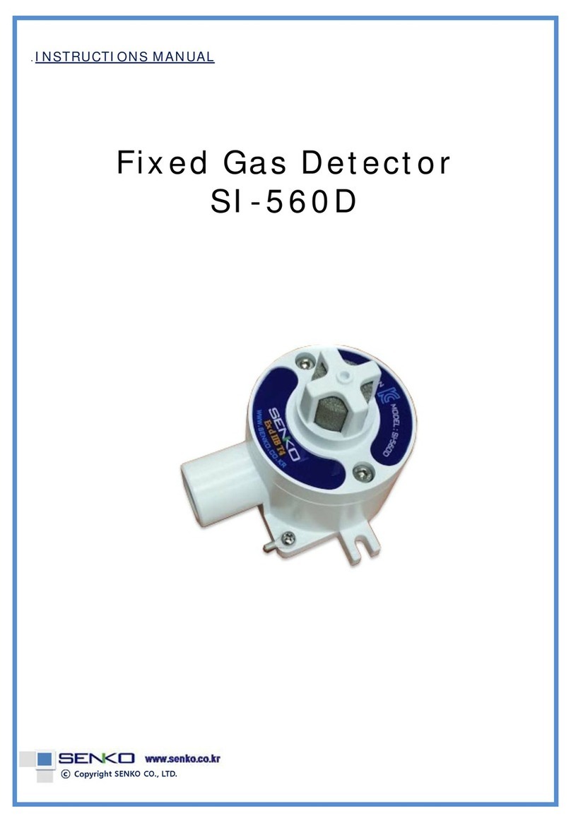
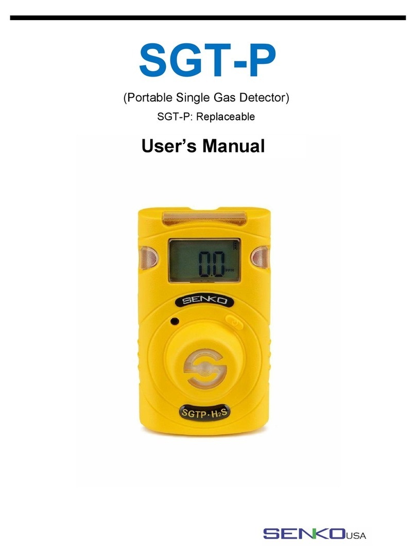
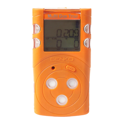
SENKO SP secure User manual

MODEL: SP secure
(Combustible Gas Leak Detector)
Operating Manual
Version 2.2

01
Guarantee and Repair
Senko Co., Ltd. guarantees the products of SP series for 12 months from the
shipping date and repairs or replaces the defected product during warranty
period. Nevertheless, Senko is not responsible for the following cases and would
not repair or replace the product at no cost, such cases as the product has been
purchased through the route that Senko does not approve, or as the product
has been damaged or deformed mechanically by misuse of the user, or as the
product has not been calibrated or replaced the parts according to processes in
the operating manual.
In the event that any defect or issue of the product occurred during warranty
period, Senko will cover all the expenses except transportation fee. After the
period of warranty, the expenses of repair or replacement of the product and
transportation will be in principle borne by the user. Senko will not be
responsible for any indirect occurrence or accident and/or damage during the
use of the product, and the guarantee shall be limited to the replacement of
parts and product. The guarantee is applied only to the users who purchased
the product at Senko’s authorized dealers or agents, and the guarantied repair is
to be performed by the expert engineers of Senko’s authorized aftercare center.
Product Introduction
SP secure is a portable gas leak detector necessary to secure user’s safety and
protect industrial facilities by detecting leakage of gas in earlier stage at the
dangerous work environment where risk of explosion always exists. As it is
configured with two buttons only, the method of operation and sensor
calibration is easy and convenient. Also the %LEL and concentration value of
inflammable gas (LPG/LNG, hydrogen, etc) can be displayed on a digital LCD
monitor.
For the safety of users, workers and operators are to be fully alerted about the
alarm circumstances by the loud alarm sound and warning icon displayed on
LCD monitor when gas concentration is detected in excess of regulatory
standard. In addition, a suction pump is built-in it and also featured with the
function of On/Off for the pump and alarm sound so that the user can set up
alarm values to properly meet with the circumstances involved and the alarm
value such set up can be adjusted to best fit to the type of gas and
circumstances of leakage. SP secure provides quick response to inflammable gas
and also prevents in advance workers from the explosion by the leakage of gas
and high risk of asphyxiation that may be resulted by the exposure to toxic gas
for a certain period of time.

Contents of Operating Manual
Product Specification ---------------------------------- 03
Names of Exterior and Display ----------------------- 04
Start and End of Operation -------------------------- 05
Operation Method ------------------------------------- 06
Backlight, ON/OFF of Sound and Pump ------------- 07
Calibration ---------------------------------------------- 07
Method of Alarm Set and Display ------------------- 09
Recharging --------------------------------------------- 11
Battery & Sensor replacement------------------------ 11
Applicable Battery ------------------------------------- 13
Notice for User ----------------------------------------- 14
02

03
Model SP secure
Detecting Gas LNG, LPG H2
(KGS701/SS1178) Xylene
Sampling
Method Auto sampling type
Sensor Type Catalytic Electrochemical IR
Detecting
Range 0~100%LEL 0~1000ppm 0~100%LEL
Response
Time(T90) Within 10 sec. Within 10 sec.
Within 75 sec. Within 90 sec.
Resolution 1 %LEL 1 ppm 1 %LEL
Display Digital LCD(Alarm, Buzzer, Pump On-off, Battery, Backlight)
Alarm Buzzer alarm & LCD Display
Gas
Concentration
Display
0~1% LEL –Digital bar
1~100% LEL –Numerical
display
0~20 ppm –Digital bar
0~1,000 ppm –
Numerical display
0~1% LEL –Digital bar
1~100% LEL –Numerical
display
Explosion
Proof Ex d ia IIB T3
Operating
Temperature - 20˚C ~ 50˚C
Power Recharger or AA Alkaline battery 3ea
Continuous
Operation More than 12 hours
Dimensions /
Weight 55m(W) x 241mm(H) x33 mm(D) / 260g
Standard
Accessories Protect Cover, Adapter for charge
Options Extension Probe(5M/10M)
1. Product Specification

04
1. Gas inlet probe
2. Gas inlet filter
3. Gas outlet
4. Gas sensor
5. Buzzer
6. LCD display
7. Gas type
8. On/Off key &
Pump On/Off key
9. Buzzer On/Off key &
Back light On keyOn/Off
10. Battery cover
11. Protection Rubber Case
4
5
6
7
3
2
1
8
9
10
11
LCD display symbols
2. Names and Functions of Exterior

05
Press Power Key for 3 seconds and the digit 3,2 and 1 shall appear on the
monitor in turn. After then power is turned off.
3. Start and End of Operation
Instrument Power-On
Press Power Key and power is turned on displaying 3,2 and 1 in order and
all icons on LCD shall be blinking three times. Afterwards during the device
is being stabilized, countdown is displayed on the screen. When
stabilization of the device is completed, mark appears with alarm sound
and then converted to Gas Detection Mode.
Under normal status, mark disappears in about 30 seconds and
concentration of the gas detected of the moment is indicated. In the
events that stabilization of the device fails, it would not convert to Gas
Detection Mode, blinking the mark with alarm sound. In this case,
calibration of sensor or A/S of the device is required.
Instrument Power-Off
Test Success Test Fail
<Caution> Appropriate calibration of the device is always required prior to
operation at the work site. Make sure if the device shows proper response to the
pertinent gas and if the part sucking gas is not blocked with foreign materials that
interfere the gas detection.

06
Set Up of LPG/LNG gas
When buzzer key is pressed under the state of power Off, type of gas presently
set shall be indicated. While buzzer key is pressed for 5 seconds, the set up for
the type of gas shall be changed to LNG from LPG. Set up for LPG can be made in
same manner as that done for LNG.
In case of LPG/LNG Detector, the device is converted to Gas
Measure Mode as shown below when power button is turned
on. Gas Measure Mode indicates the concentration of gas,
operating status of suction pump, alarm sound On/Off status,
battery level on LCD and it displays the concentration of
flammable gas by %LEL and by PPM unit for Hydrogen. In the
event that gases are detected, it indicates the value of
concentration in real time and, if it exceeds the 1st and 2nd
alarm standard, the measured value shall be displayed blinking repeatedly along
with mark and LO or HI indication.
The gas leakage detector raises an alarm along with digital bar when gas leakage
is detected even in small amount, and the concentration value shall be reduced
and alarm also shall be ceased when moved out to safe region where normal
concentration value is measured. The alarm sound raised by the detection in the
beginning stage can be stopped (OFF) with the Alarm Sound Off Button but the
1st and 2nd alarm sound can not be stopped. (Once alarm sound is raised, the
mark shall not be disappeared even though the device is moved out to safe region
(Can delete it by the OFF of Power Key). When the concentration value of the gas
measured exceeds the maximum measuring range, it is indicated as the max value
and it will be kept blink with one second interval. Also alarm sound relevant to the
standard of 2nd alarm shall be raised along with indication.
4. Operation Method
Detection Mode

07
On/Off of Pump
On/Off of Backlight and Sound
Alarm sound is also set to turn ON state when power key is pressed. All the
following operations for ON/OFF of the Alarm Sound can be performed in the
same way as that for suction pump above by using Alarm Sound key.
Suction pump is set to turn ON when
power key is pressed. Press power key
one more time to OFF suction pump.
When power key is input once again, the
function of suction pump returns to ON
state as initially set.
<Caution> Gas leakage detection can not be properly performed if the Suction
Pump key is laid in OFF state. As the setting of OFF mode is to save battery while
the device is not in service, Suction Pump has to be set ON all the time during the
measure of gas leakage.
5. Backlight, ON/OFF of Sound and Pump
6. Calibration

08
icons shall blink if buzzer key is pressed for 3 seconds under the state power
key is pressed simultaneously. Press power key at this state to enter into standby
calibration mode. Calibration shall be completed in 10 second while processing
countdown from 10,9,8…down to 3,2,1. When calibration is successfully completed,
it returns to Gas Measure Mode with alarm sound after the icons being blinked
for 3 seconds.
…
In case standby calibration is failed, it returns to Gas Measure
Mode with alarm sound after the icons being blinked for 3
seconds but the icons shall remain appeared in this case. If
such occurrence happens repeatedly, please contact our agent or
A/S center as the sensor is required to be replaced.
Press buzzer key for three seconds simultaneously at state pressing power key.
Then icon blinks. At this time, icon blinks if press buzzer key. After press
power key for five seconds, it enters to Standard Gas Calibration Mode. Initial
concentration is 20%LEL.
Press power key to change value, and press buzzer key to save value. Calibration
starts to setting concentration if press buzzer key at final number. For canceling
calibration, press buzzer key.
Calibration is done for 20 seconds countdown. When calibration is successfully
completed, icon blinks and it appears concentration of standard gas. After this
time, standard gas is not connected, it returns to Gas Measure Mode.
Fresh air Calibration
Standard Gas Calibration
<Caution> As the calibration is conducted under the assumption that the concen-
tration of oxygen in fresh air is 29.9% and that of flammable gas is 0%LEL and the
same of toxic gas is 0ppm, the fresh air calibration must be conducted in fresh air
where no influences of other gases are effective. Hence, it is not desirable conducting
fresh air calibration in a closed space and should be very careful not to conduct
under the working environment where gases can be inhaled by workers or operators.

09
5초
Change value
Save value and
Start calibration
…
In case standby calibration is failed, it returns to Gas Measure
Mode with alarm sound after the icons being blinked for 3
seconds but the icons shall remain appeared in this case. If
such occurrence happens repeatedly, please contact our agent or
A/S center as the sensor is required to be replaced.
Gas Combustible gas Hydrogen Xylene
Concentration 20%LEL
(1%vol CH4) 500 ppm 0.54%vol
(Propane)
9. Method of Alarm Set and Display
Alarm Set
Concentration of Calibration Gas Set to Instrument
When power key and buzzer key is pressed for 3 seconds under the state of
power OFF, icons shall appear blinking on LCD and indicates LO. Press
power key one more time under this state to enter into alarm set up mode. When
power key is pressed at this point, system shall be entering into the 1st alarm
change mode and, when buzzer key is pressed, HI shall be displayed on the
monitor and then moves to the 2nd alarm set up mode. In order to return to Gas
Measure Mode without changing alarm set value, use buzzer key to move.

10
Power OFF
Save value
Change value
Save value
Change value
In case 1st alarm is raised and power key is pressed by a worker or operator who
perceived the status of 1st alarm, the alarm sound only shall be stopped but the
device shall still remain in operation state. When 2nd alarm is raised, the workers
should quickly escape from the work site to safe region. Termination of alarm in
this case is possible only by turning power key Off at a place where gas
concentration indicates normal value (Alarm shall be continuously raised unless the
power key is turned off at an area of normal concentration value).
The alarm sound of 1st battery is same as that of the 1st alarm and, when power
key is pressed, the alarm and vibration only shall be ceased but icons shall be kept
blinking. The alarm sound of 2nd battery is same as that of 2nd alarm and the
blink of icons can not be deleted by the users. The alarm and power shall be off 10
seconds after the raise of alarm.
In case of failure of test and calibration, icons shall blink with alarm sound.
Gas Combustible gas Hydrogen Xylene
1st 20%LEL 100 ppm 20%LEL
2nd 40%LEL 500 ppm 40%LEL
Alarm Set Point
Alarm Display
After setting the 1st alarm value, returns to the 1st alarm set up mode that is the
alarm mode initially set. Use arrow key to enter into the 2nd alarm set up mode or
to return to Gas Measure Mode. Method of 2nd alarm set up is same as that of the
1st alarm setting.
While returning to Gas Measure Mode through the 2nd alarm set up mode,
countdown shall be proceeded. When countdown is completed, system shall be
converted to Gas Measure Mode.

11
Alarm Standard for Alarm
LCD Display Alarm Sound
1st Alarm
When
exceeding th
e
value set for 1st a
larm
and
indicates
LO
2nd Alarm
When
exceeding th
e
value set for 2nd
alarm
and
indicates
HI
Low
One
level only left
unused
Blinking
Battery
Dead
is
exhausted
Blinking
Battery
Test Failure
Failure
of sensor te
st
or calibration
Displays icon
8. Recharging
When adapter for recharge is equipped
with the device, battery recharge mode
shall be displayed on screen even under
the mode of gas measure or power Off
state. Power shall be Off when adapter
is removed.
Recharging End recharge
9. Replacement of Battery and Sensor
<Caution> The values set for alarm of the device are set in conformity with the
alarming standards internationally required by gases. Therefore, the set value for
alarm by gases can be modified by the approval of the manager responsible for the
area where the device is used.
Following tools and parts are necessary to replace sensor and battery of SPsecure.
- Tool : + Driver
- Energizer No.E91, EN91 battery for replacement or rechargeable battery
- Sensor for replacement
- Sensor filter for replacement

12
<Caution>
1. No battery replacements or disassembly of product are permitted at potential
explosion or dangerous area.
2. Please be noted that replacement of parts may cause damage to the fundamental
safety capabilities of the device.
3. Sensors for replacement must be the one exclusively for SP Secure. The use of
other sensors may cause problems in the detection of gas leakage or cause errors in
the measurements.
4. The device is to be disassembled only for the replacement of battery or sensor and
it has to be calibrated by utilizing standard gas during reassembly.
- Finish operation of the device.
- Replace sensor and battery referring to the picture below.
- Operate the device after replacing sensor and then adjust zero point and
standardize the device.
- Conduct gas calibration (When battery only is replaced, standard gas calibration
shall not be carried out)
9
1 2
3
4
5
8
6
11 12
7 10
1. Label(Membrane)
2. Front Cover
3. Upper cover
4. Sensor bracket
5. Sensor
6. Pump
7. PCB
8. Packing body
9. Rear Cover
10.Machine Screw
11.Battery
12.Battery Cover
Disassembly

13
<Caution> It is absolutely prohibited to replace battery at potential explosion areas
or dangerous regions. Specifications of the batteries applicable to this device are as
follows.
- Disposable alkaline battery : Energizer No. E91, Energizer No.EN91
- Rechargeable battery : Panasonic Rechargeable BATTERY
HHR-3MRT, 1.2V
Batteries other than specified above are not allowed to use in dangerous area.
<Caution> Throwing battery into fire or disassembly by force may cause explosion.
Disposal of used battery should be performed in accordance with the guideline of the
pertinent country or the work site.
10. Applicable Battery

14
Please use the instrument in the range of the applicable temperature, humidity and
pressure that are appropriate for the specification of the product. Using the
instrument beyond this range may cause malfunction or glitch of the instrument. .
Gas concentration measurement value by the sensor or the instrument can vary
according to the environment at site (temperature, pressure and humidity). Therefore
the calibration of the instrument should be performed at the same or similar
environment as that of the instrument use (temperature, pressure and humidity),
If temperature changes sharply during use of the instrument (for instance, using the
instrument at places of far different temperatures between indoor and outdoor), the
value of the measured gas concentration can be changed suddenly. Please use it
after the gas concentration value is stabilized. .
Severe vibration or shock to the instrument may cause the sudden change of value
of the measured gas concentration. Please use it after the value of gas concentration
is stabilized. Excessive shock to the unit can lead to trouble of the sensor or the
instrument.
11. Notice for User

15
Other manuals for SP secure
1
Table of contents
Other SENKO Gas Detector manuals

