Sensata M700 Series User manual

| M700
HYDRAULIC PUMP MOTOR CONTROLLER
INTERFACE MANUAL

www.sensata.com
| M700 SERIES
HYDRAULIC PUMP MOTOR CONTROLLER
2
Copyright © 2021 Sensata Technologies, Inc.
CONTENTS
OVERVIEW ........................................................................................................................................3
INSTALLATION AND WIRING.............................................................................................................5
MOUNTING THE CONTROLLER.....................................................................................................5
CONNECTIONS ..............................................................................................................................7
High current connections.............................................................................................................8
Low current connections..............................................................................................................8
CONTROLLER WIRING: TYPICAL CONFIGURATION...................................................................9
KSI Wiring ...................................................................................................................................10
Main Contactor...........................................................................................................................10
Interlock Switch..........................................................................................................................11
Circuitry Protection Devices.......................................................................................................11
Throttle Wiring ...........................................................................................................................11
PROGRAMMABLE PARAMETERS....................................................................................................16
VOLTAGE MENU..........................................................................................................................17
CURRENT MENU .........................................................................................................................18
SPEED MENU...............................................................................................................................18
THROTTLE MENU........................................................................................................................19
MISCELLANEOUS PARAMETERS .................................................................................................23
MONITOR MENU............................................................................................................................24
DIAGNOSTICS AND TROUBLESHOOTING .......................................................................................25
PC APP DIAGNOSTICS.................................................................................................................25
LED DIAGNOSTICS.......................................................................................................................27
MAINTENANCE .......................................................................................................................28
CLEANING....................................................................................................................................28
FAULT HISTORY ...........................................................................................................................29

www.sensata.com
| M700 SERIES
HYDRAULIC PUMP MOTOR CONTROLLER
3
Copyright © 2021 Sensata Technologies, Inc.
OVERVIEW
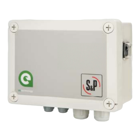
M700 is a high-power hydraulic pump controller that provides
fully programmable control of DC series wound motors. It
features microprocessor-based logic with programmable
parameters and offers maximum flexibility for minimum cost.
This means the controller can be tailored to the needs of
specific applications. In addition to configuration flexibility,
use of the programmer offers diagnostics and test capability. It
is the ideal solution for hydraulic pump motor control on
aerial work platform (AWP) equipment.
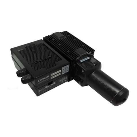
Fig. 1 M700-VR1
hydraulic pump motor
controller.
The M700 controller offers superior operator control of motor
speed and torque.
Controllable Power
➢Pulse Width Modulation (PWM) control with programmable
speed, acceleration rate, and current limit.
➢Short duration boost capability (10 sec, 110% of 2 min current
rating). Allows clearing of obstacles, climbing ramps.
➢16 kHz PWM frequency for near silent operation.
➢High efficiency, silent operation. Operating costs, heat-sinking
requirements, motor and battery losses reduced. Low-end
torque, range, and battery life maximized.
1

www.sensata.com
| M700 SERIES
HYDRAULIC PUMP MOTOR CONTROLLER
4
Copyright © 2021 Sensata Technologies, Inc.
Programmable and Flexible
➢Fully programmable via Sensata PC programming software.
➢Supports multiple throttle types and High Pedal Disable (HPD)
options.
➢LED output for easy system troubleshooting via flash codes.
➢Fully programmable analog throttle input for precise speed
control with a variety of signal sources.
➢Programmable under voltage cutback caters to different
battery types.
➢CAN type input for throttle function
➢Interlock function with a digital signal input that can be easily
disabled/enabled by setting.
➢Two-driver output with max 2A.
Robust Safety and Reliability
➢Redundant hardware and software watchdog timers.
➢MOSFET short-circuit protection functions.
➢Programmable HPD function prevents controller operation if
throttle is applied before key is turned on.
➢Contactor fault detection: controller shuts down safety if the
main contactor opens.
➢Contactor protection functions minimize high current arcing to
prevent contact pitting and thus prevent contactor weld
failures.
➢Undervoltage cutback and shutdown functions protect against
low battery voltage, including low voltage caused by external
loads.
➢Electrical isolation to heat sink: 500VAC.
➢Rugged housing meets IP54 environmental ratings.
➢Full power operation over -40°C to 50°C environment
temperature range.
Familiarity with the controller will help you install and operate it
properly. We encourage you to read this manual carefully. If you have
questions, please contact the Sensata service office nearest you.

www.sensata.com
| M700 SERIES
HYDRAULIC PUMP MOTOR CONTROLLER
5
Copyright © 2021 Sensata Technologies, Inc.
INSTALLATION AND WIRING
MOUNTING THE CONTROLLER
The M700 controller can be oriented in any position and meets
the IP54 ratings for environmental protection against dust and
water. However, the location should be carefully chosen to
keep the controller clean and dry. If a clean and dry mounting
location cannot be found, a cover must be used to shield the
controller from water and contaminants.
The controller’s outline and mounting hole dimensions are
shown in Figure 2. When selecting the mounting position, be
sure to also take into consideration that access is needed at the
end of the controller to plug the programming cable into its
connector. To ensure full rated power, the controller should be
fastened to a clean, flat metal surface with four 6 mm (1/4")
diameter screws, using the holes provided. Although not
usually necessary, a thermal joint compound can be used to
improve heat conduction from the controller heatsink to the
mounting surface. You will need to take steps during the design
and development of your application product to ensure that its
EMC performance complies with applicable regulations;
suggestions are presented in Appendix A.
2

www.sensata.com
| M700 SERIES
HYDRAULIC PUMP MOTOR CONTROLLER
6
Copyright © 2021 Sensata Technologies, Inc.
Fig 2 Mounting dimensions,
M700-VR1 controller
.

www.sensata.com
| M700 SERIES
HYDRAULIC PUMP MOTOR CONTROLLER
7
Copyright © 2021 Sensata Technologies, Inc.
caution
CONNECTIONS
The controller’s connectors are all conveniently located on one end:
Working on electrical systems is potentially dangerous. You should
protect yourself against uncontrolled operation, high current arcs, and
outgassing from lead acid batteries.
UNCONTROLLED OPERATION — Some conditions could cause the
hydraulic pump system to run out of control. Disconnect the motor or
make sure the pump system has enough room to operate before
attempting any work on the motor control circuitry. Note: If the wrong
throttle input signal type is selected with the programming device, the
pump system may suddenly begin to operate.
HIGH CURRENT ARCS — Batteries can supply very high power, and arcs
can occur if they are short circuited. Always open the battery circuit
before working on the motor control circuit. Wear safety glasses and
use properly insulated tools to prevent shorts.
LEAD ACID BATTERIES — Charging or discharging generates hydrogen
gas, which can build up in and around the batteries. Follow the battery
manufacturer’s safety recommendations. Wear safety glasses.

www.sensata.com
| M700 SERIES
HYDRAULIC PUMP MOTOR CONTROLLER
8
Copyright © 2021 Sensata Technologies, Inc.
High current connections
This controller has three high-current busbars: B+, B- and M-. The
busbars are tin-plated solid copper.
Cables used for the battery and motor connections must be heavy
enough to carry the high current required. A minimum size of 25 mm2 (#4
AWG) is recommended.
Connections to the controller busbars should be made with lugs
suitable for the cable used, fastened by M8 bolts and nuts. When
tightening the bolts, two opposing wrenches should be used. Failure to
use the double-wrench technique could cause undue strain to be placed
on the internal connections, and could also result in cracked seals around
the busbars.
Low current connections
This controller has six low-current connections: four 6.35 mm push-on
terminals (J1, J2, J3, and J5), and two 4-pin connectors (J4 and J6).
Table 2 Low Current Connections
J1
Keyswitch
J2
Wire 1 of 2-wire throttle; Pot High of 3-wire.
J3
Wire 2 of 2-wire throttle; Pot Wiper of 3-wire throttle.
J4
4-pin connector: see Table 3.
J5
Reverse signal output / main contactor coil driver.
J6
4-pin connector: see Table 4.
For the control wiring, 0.75 mm2 (#18 AWG) vinyl insulated stranded wire
is recommended.
The mating connector for J4 is a 4-pin Molex Mini-fit Jr. or equivalent.
Either an external Status LED or a USB2UART programmer can be
connected to J4. The pinout is as follows.
Table 1 High Current Connections
B+
Battery+ and motor armature
B-
B-
M-
Motor field (controller output)

www.sensata.com
| M700 SERIES
HYDRAULIC PUMP MOTOR CONTROLLER
9
Copyright © 2021 Sensata Technologies, Inc.
Note: When J4 is used for a Status LED, a jumper must be added between
pins J4-1 and J4-4 as shown in the basic wiring diagram (Figure 3).
The mating connector for J6 is a 4-pin TE Mini-Universal MATE-N-LOK or
equivalent. The pinout is as follows.
CONTROLLER WIRING: TYPICAL CONFIGURATION
Figure 3 shows the typical wiring configuration for most applications. The
interlock switch is typically a seat switch, tiller switch, or foot switch, the
interlock function can be disable in the setting. The throttle shown is a 3-
wire pot; other types of throttles can also be used.
PIN PROGRAMMER STATUS LED
J4-1 Data input from programmer (Rx). Status LED enable.
J4-2 GND GND
J4-3 Data output to programmer (Tx). Status LED output.
J4-4 +12.7V +12.7V
Table 3 J4 connector pinout
Table 4 J6 connector pinout
PIN
PROGRAMMER
J6-1
Driver output
J6-2
Interlock
J6-3
CANL
J6-4
CANH

www.sensata.com
| M700 SERIES
HYDRAULIC PUMP MOTOR CONTROLLER
10
Copyright © 2021 Sensata Technologies, Inc.
KSI
J1
THROTTLE POT
WIPER
J2
J3 THROTTLE POT
LOW
+12V
TX
RX
GND
CANH
CANL
INTERLOCK
Reserved
B+
M-
B-
Main Contactor
Driver J5
A1
A2
S1
S2
MAIN
PRECHARGE RESISTOR
J6-4
J6-3
J6-2
J6-1
1
2
3
4
J4
MAIN CONTACTOR
POLARITY
PROTECTION
DIODE
FUSE
FUSE
THROTTLE POT
Fig.3 Typical wring diagram
KSI Wiring
The keyswitch input (KSI) circuit includes input from the keyswitch and from
the various interlocks. The controller KSI is used to turn the controller on and
off. KSI is turned on by connecting it to battery B+. Any positive voltage greater
than about 16 volts will turn on the controller, but usually the full vehicle battery
voltage is used. KSI draws up to 120 mA with the programmer connected.
In its simplest form, KSI is operated by a keyswitch that turns the vehicle off and
prevents unauthorized use. The keyswitch should also turn off the main contactor
This will act as a safety feature by removing power from the motor control system
when the keyswitch is turned off.
Main Contactor
A main contactor should be used with the controller. Otherwise, the controller’s
fault detection will not be able to fully protect the controller and hydraulic system
from damage in a fault condition. The main contactor allows the controller and
motor to be disconnected from the battery. This provides a significant safety
feature, because it means the battery power can be removed from the hydraulic
system if a controller or wiring fault results in battery power being applied to the

www.sensata.com
| M700 SERIES
HYDRAULIC PUMP MOTOR CONTROLLER
11
Copyright © 2021 Sensata Technologies, Inc.
motor inappropriately.
The controller provides a low-side contactor coil driver (at J5) for the main
contactor. The driver output is rated at 1 amp and is short-circuit protected.
It is recommended that a coil suppression diode be included, as shown in the
wiring diagrams. This protects the contactor coil driver from inductive voltage
kickback spikes when the contactor is turned off.
Interlock Switch
The interlock switch, which is typically implemented as a seatswitch or a
hand/foot activated deadman switch, provides a safety interlock to ensure that
an operator is present in order for the system to run.
Circuitry Protection Devices
To protect the control circuitry from accidental shorts, a low current fuse (ap-
propriate for the maximum current draw) should be connected in series with
the battery feed to the keyswitch. Additionally, a high current fuse should be
wired in series with the main contactor to protect the motor, controller, and
batteries from accidental shorts in the power system. The appropriate fuse for
each application should be selected with the help of a reputable fuse
manufacturer or dealer. The standard wiring diagrams (Figure 3) show the
recommended location for each fuse.
Throttle Wiring
Four throttle types can be used with this controller:
TABLE 5 WIPER INPUT: THROTTLE THRESHOLD VALUES
THROTTLE
TYPE
PARAMETER
MINIMUM
THROTTLE FAULT
MAXIMUM
THROTTLE FAULT
0
0-5kΩ
2-wire potentiometer
-
5.5kΩ
1
5kΩ-0
2-wire potentiometer
-
5.5kΩ
2
0-5V
Single-ended input
-
5.5V
3
CANOPEN command
-
1023
Throttle Type 0
Wiring for Type 0 throttles is simple: just connect the two wires to
the J2 and J3 push-on terminals; it doesn’t matter which wire goes
on which terminal. With Type 0 throttles, resistance increases as

www.sensata.com
| M700 SERIES
HYDRAULIC PUMP MOTOR CONTROLLER
12
Copyright © 2021 Sensata Technologies, Inc.
the applied throttle is increased. Mechanical pot boxes and foot
pedals are Type 0 throttles. It doesn’t matter which wire goes on
which terminal, and the wires can be extended as required.
Fig 4 Wiring for
0–5kΩ
throttle (“Type
0”).
Some pot boxes have a built-in microswitch, eliminating the need to
install a separate pedal actuated microswitch. It is important that a
pedal microswitch be included in the circuit as shown in Figure 3 to
allow the microcontroller a few milliseconds to boot up, run
diagnostics and safety checks, and then be ready in standby before
receiving the throttle signal.
Any pot box that can provide a nominal 0–5kΩ output will
work as a Type 0 throttle input.
If a pot box is used, it must be mounted so as to allow
connection be-tween the pot box lever arm and the vehicle
accelerator linkage. Use of a second return spring on the pedal, in
addition to the pot box return spring, is required to prevent an
uncontrollable full-on throttle input (which could happen if there
was a single spring, and it broke). If the self-contained pot box
spring is insufficient to return the pedal by itself, two additional
pedal return springs must be used. It is also required that the
accelerator pedal hit a mechanical stop at its full-on position just
before (≈1 mm) the pot box lever hits its own full-on stop. This
mechanical stop will prevent the pot box lever arm from bending if
undue force is put on the pedal. Protection of the pot box from
water and dirt will help avoid problems of corrosion and electrical
leakage. After the pot box has been mounted, operation of the pot
can be tested by measuring the resistance between the two wires
with an ohmmeter. With the pedal not applied, the resistance
should be less than 50 ohms. As the pedal is applied, the resistance
should rise smoothly until it reaches a value between 4500 and
5500 ohms. Values below 4500 ohms may cause a reduction in
efficiency and top speed; however, you still can get top speed by
lowering the Throttle Max setting. Values above 5500 ohms indicate
a defective pot box and will cause controller shutdown.
Throttle Type 1
Wiring for Type 1 throttles is the same as for Type 0 throttle; again,

www.sensata.com
| M700 SERIES
HYDRAULIC PUMP MOTOR CONTROLLER
13
Copyright © 2021 Sensata Technologies, Inc.
it doesn’t matter which wire goes on which terminal. With these
throttles, resistance is in an inverse relationship to applied throttle;
that is, resistance decreases as applied throttle is increased.
Fig 4 Wiring for
5k–0Ω
throttle (“Type
0”).
Throttle Type 2
With Type 2 throttles, the controller looks for a voltage signal at J3. Zero
throttle request corresponds to 0 V and full throttle request to 5 V. A
variety of devices can be used with this throttle input type, including voltage
sources, current sources, and electronic throttles. The wiring for each is
slightly different, as shown in Figure 10, and they have varying levels of
throttle fault protection.
When a voltage source is used as a throttle, it is the responsibility of the
OEM to provide appropriate throttle fault detection. For ground referenced
0–5V throttles, the controller will detect open breaks in the wiper input but
cannot provide full throttle fault protection. To use a current source as a
throttle, a resistor must be added to the circuit to convert the current source
value to a voltage; the resistor should be sized to provide a 0–5V signal
variation over the full current range. It is the responsibility of the OEM to
provide appropriate throttle fault detection.
There are many electronic foot pedals on the market; for wiring, consult
the instructions that are provided with the foot pedal.
Fig 5 Wiring for type 2
throttle

www.sensata.com
| M700 SERIES
HYDRAULIC PUMP MOTOR CONTROLLER
14
Copyright © 2021 Sensata Technologies, Inc.
Throttle Type 3
Communicates with ECU and other devices via CAN. Main microcontroller of
this controller can send controller’s state and the measure values to other devices.
The communication protocol should follow CANOpen protocol.
M700-VR1 will set as slave station, and support NMT, PDO and Emergency message.
1. Common
Baud rate: Configurable, default value is 250kbps (Max speed), and it
is adjustable.
ID format: Standard ID (11bit).
Node type: M700-VR1 is a slave node.
Node ID: Configurable, default value is 1.
2. PDO
TPDO1 (SlaveMaster, COB-ID=0x180+Node-ID, length=8)
Byte 0
Byte 1
Byte 2
Byte 3
Byte 4
Byte 5
Byte 6
Byte 7
Status
word 1
Lo
Status
word 1
Hi
Throttle
Lo
Throttle
Hi
Battery
Lo
Battery
Hi
Heatsink
temperature
Lo
Heatsink
temperature
Hi
Unsigned 16
Bit 0: interlock input status
Bit 1: drive 1 output status
Bit 2: drive 2 output status
Bit 3-15: reserved
Unsigned 16
0-1023: 0-100%
Unsigned 16
0-3600: 0-36.0V
Unsigned 16
0-150: --25-+125°C
RPDO1 (MasterSlave, COB-ID=0x200+Node-ID, length=8)
Byte 0
Byte 1
Byte 2
Byte 3
Byte 4
Byte 5
Byte 6
Byte 7
Control
word Lo
Control
word Hi
Throttle
reference
Lo
Throttle
reference
Hi
reserved
reserved
reserved
Reserved
Unsigned 16
Bit 0: interlock enable
Bit 1: drive 1 enable
Bit 2-15: reserved
Unsigned 16
0-1023: 0-100%
3. NMT
NMT Module Control (MasterSlave, COB-ID=0x000, length=2)
Byte 0
Byte 1
NMT type
Node ID
0x01: start node
0x02: stop node
0x80: enter pre-operational
0x81: reset node
0x82: reset communication
0: broadcast
>0: special node

www.sensata.com
| M700 SERIES
HYDRAULIC PUMP MOTOR CONTROLLER
15
Copyright © 2021 Sensata Technologies, Inc.
NMT Node Guarding Request (MasterSlave, COB-ID=0x700+Node-
ID, remote frame)
NMT Node Guarding Response (SlaveMaster, COB-ID=0x700+
Node-ID, length=1)
Byte 0
Node Status
Bit 0-6: 0-boot up, 4-stopped, 5-operational, 127-pre-operational
Bit 7: toggle bit
4. Emergency Object
Emergency Object (SlaveMaster, COB-ID=0x080+Node-ID, length=8)
Byte 0
Byte 1
Byte 2
Byte 3
Byte 4
Byte 5
Byte 6
Byte 7
Error code
Hi
Error code
Lo
reserved
reserved
reserved
reserved
reserved
reserved
Unsigned 8
High digit of
error code
Unsigned 8
low digit of error
code
5. Sequence
M700-VR1 should design 4 states for CANOpen communication:
Initializing, Pre-operational, Operational, Stopped. State machine of
CANOpen communication is shown as below:
M700-VR1 changes state after received NMT Module Control frame.
When M700-VR1 change state from initializing to pre-operational, it
should send NMT Node Guarding Request frame actively. (node
status is 0)
In all states, M700-VR1 send NMT Node Guarding Response frame
after received NMT Node Guarding Request frame. (Toggle bit 7 every
time)
In all states, M700-VR1 send Emergency Object once when any fault
happened.
Only in Operational state, M700-VR1 executes command in RPDO1,
and send TPDO1 frame after received RPDO1 frame.

www.sensata.com
| M700 SERIES
HYDRAULIC PUMP MOTOR CONTROLLER
16
Copyright © 2021 Sensata Technologies, Inc.
Fig 6 CANopen
communication
sequence
6. Error Handle
In operational state, if M700-VR1 not receive RPDO1 for 200ms, it will
return to pre-operational state and clear all command.
PROGRAMMABLE PARAMETERS
The M700-VR1 programmable parameters allow the pump system’s
performance characteristics to be customized to fit the needs of
individual applications or system operators. Programming can be
done with a UART2USB adapter and PC APP.
Voltage
Rating Voltage
Under Voltage Cutback
Under Voltage Cutback Rate
Under Voltage Cutback Off
Over Voltage
Current
Max Current Limitation
Continue Current Limitation
Speed
Accel Rate
3
Initializing
Pre-
operational
Operational
Stopped
Initialized
NMT Cmd
0x01
NMT Cmd
0x01
NMT Cmd 0x80
Or comm. lost
NMT Cmd
0x02
NMT Cmd
0x02
NMT Cmd
0x80
NMT Cmd
0x81 or 0x82
NMT Cmd
0x81 or 0x82
NMT Cmd
0x81 or 0x82

www.sensata.com
| M700 SERIES
HYDRAULIC PUMP MOTOR CONTROLLER
17
Copyright © 2021 Sensata Technologies, Inc.
Quick Start
Max Speed
Throttle
Throttle Type
Throttle Deadband
Throttle Max
Throttle Map
Misc
HPD
Boost
Main Contactor Driver
Contactor Pull In
Contactor Holding
Contactor Protection
Contactor Open Delay
Interlock
CAN
CAN ID
CAN Baud Rate
The individual parameters are presented as follows in the
parameter charts:
VOLTAGE MENU
PARAMETER
ALLOWABLE
RANGE
DEFAULT VALUE
DESCRIPTION
Rating Voltage
24V
36V
24
Set this parameter to match the battery pack of your
vehicle
Under Voltage Cutback
50-100(%)
80
The controller’s circuitry requires a minimum battery
voltage to function properly. When battery voltage drops,
reducing the controller’s output to the motor allows the
battery to recover. The parameter sets the threshold
voltage below which controller output will start to be
reduced. The programmed value is a percentage of the
battery voltage.
Under Voltage Cutback
Rate
0-50(A/0.1V)
5
This is a proportional value. Use the current voltage minus
the cutoff voltage and then the ratio to the current output
current

www.sensata.com
| M700 SERIES
HYDRAULIC PUMP MOTOR CONTROLLER
18
Copyright © 2021 Sensata Technologies, Inc.
Under Voltage Cutback Off
50-100(%)
75
The Under Voltage Cutoff parameter sets the voltage at
which controller
output will be cut off completely. The programmed
value is a percentage of the battery voltage. The
Under Voltage Cutoff parameter can only be set to values
smaller (lower) than the programmed Under Voltage
Cutback.
Over Voltage
2500-3000
(Battery
Voltage*100)
2800
The Over Voltage parameter sets the voltage at which
controller will stop run to protect the circuit from
high voltage. It is the highest voltage at that rating voltage.
CURRENT MENU
PARAMETER
ALLOWABLE
RANGE
DEFAULT
VALUE
DESCRIPTION
Max Current Limitation
0-3000(setting
current*10)
1500
Max Current Limitation parameter sets the
max current that the software allows the
controller's output
SPEED MENU
PARAMETER
ALLOWABLE
RANGE
DEFAULT
VALUE
DESCRIPTION
Accel Rate
2-30(100ms)
10
The Accel Rate defines the time it takes the
controller to accelerate from 0%
output to 100% output when full throttle is
applied.
Larger values represent a longer
acceleration time and therefore a gentler
start. For faster starts, adjust the Accel Rate to
a smaller value.
Quick Start
2-30(100ms)
10
When the throttle is moved from zero rapidly,
the quick start feature is activated.
The Quick Start acceleration rate then replaces
the normal acceleration rate as
set by the Accel Rate parameter).
The Quick Start parameter can only be set to
values smaller (faster) than
the programmed Accel Rate.

www.sensata.com
| M700 SERIES
HYDRAULIC PUMP MOTOR CONTROLLER
19
Copyright © 2021 Sensata Technologies, Inc.
Max Speed
0-1000(percentage*10)
1000
Defines the maximum requested motor
speed at full forward throttle, as %
PWM. Partially-applied throttle is scaled
proportionately; e.g., 40% applied
throttle corresponds to a request for 40% of
the programmed Max Speed
value. Example: if Max Speed is set to 80%, a
40% applied forward throttle
corresponds to a 32% request
(0.80*0.40=0.32).
THROTTLE MENU
PARAMETER
ALLOWABLE
RANGE
DEFAULT VALUE
DESCRIPTION
Throttle Type
0:0-5K
1:5K-0
2:0-5V
3:CANOPEN
0:0-5k
The M700-VR1 controllers accepts a variety of throttle
inputs. The Throttle Type parameter can be programmed
as follows:
0: 2-wire potentiometer, 0–5kΩ input
1: 2-wire potentiometer, 5kΩ–0 input
2: single-ended 0–5V input
Throttle Deadband
10-500
(percentage*10)
200
The Throttle Deadband parameter defines the neutral
deadband as a per-centage of the full throttle range.
Increasing the Throttle Deadband setting will increase the
neutral range. This parameter is especially useful with
throttle assemblies that do not reliably return to a well-
defined neutral point, because it allows the deadband to
be defined wide enough to ensure that the controller goes
into neutral when the throttle mechanism is released.
Throttle Max
100-1000
(percentage*10)
800
The Throttle Max parameter defines the percentage of
throttle movement at which 100% output is requested.
Decreasing the Throttle Max setting reduces the full stroke
necessary to produce full controller output. This
parameter allows reduced-range throttle assemblies to be
accommodated.

www.sensata.com
| M700 SERIES
HYDRAULIC PUMP MOTOR CONTROLLER
20
Copyright © 2021 Sensata Technologies, Inc.
Throttle Map
0-100(%)
50
The Throttle Map parameter modifies the vehicle’s
response to the throttle input. Setting Throttle Map at
50% provides a linear output response to throttle position.
Values below 50% reduce the controller output at low
throttle settings, providing enhanced slow speed
maneuverability. Values above 50% give the vehicle a
faster, more responsive feel at low throttle settings. The
Throttle Map value is the controller output at half throttle,
as a percentage of the Max Speed. Half throttle is the mid
point of the throttle’s active range, which is the range
from zero output (at the Deadband setting) to 100%
output (at the Throttle Max setting).
THRTL DEADBAND
The Throttle Deadband parameter defines the pot wiper voltage
range the controller interprets as neutral. Increasing the throttle
deadband setting increases the neutral range. This parameter is
especially useful with throttle assemblies that do not reliably return
to a well-defined neutral point, because it allows the deadband to be
defined wide enough to ensure that the controller goes into neutral
when the throttle mechanism is released.
Examples of deadband settings (30%, 10%, 0%) are shown in
Figure 6 for throttle types 0 through 3, using a nominal 5kΩ–0
potentiometer (where applicable).
The programmer displays the throttle deadband parameter as
a percentage of the nominal wiper voltage range and is adjustable
from 4% to 90%, in 1% increments. The default deadband setting is
10%. The nominal wiper voltage range depends on the throttle type
selected.
This manual suits for next models
1
Table of contents
