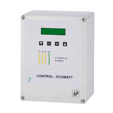
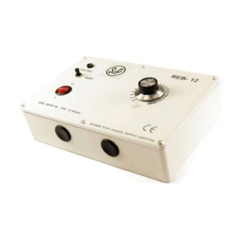
S&P CONTROL ECOWATT User manual

CONTROL ECOWATT BASIC


3
ESPAÑOL
ÍNDICE
1. GENERAL .................................................................................................4
1.1. Avisos ................................................................................................4
1.2. Normas de seguridad y marcado CE................................................4
1.3. Recepción y almacenaje ................................................................... 5
2. PRESENTACIÓN PRODUCTO ...................................................................5
3. INSTALACIÓN...........................................................................................6
3.1. Dimensiones ....................................................................................6
3.2. Requerimientos de instalación......................................................... 6
3.3. Conexión eléctrica ............................................................................6
4. PUESTA EN MARCHA............................................................................... 7
4.1. Modos funcionamiento .....................................................................7
4.2. Leds indicativos (D9-D12).................................................................8
4.3. Salida 230V (J9).................................................................................9
4.4. Salida +24Vdc (J10) ...........................................................................9
5. MANTENIMIENTO ....................................................................................9
6. GESTIÓN RESIDUOS ................................................................................9
7. ESQUEMA DE CONEXIÓN ......................................................................10
ESPAÑOL

4
ESPAÑOL
1. GENERALIDADES
Le agradecemos la confianza depositada en S&P mediante la compra de
este producto, que ha sido fabricado según reglas técnicas de seguridad,
conforme a las normas de la CE.
Antes de instalar y poner en funcionamiento este producto, lea atenta-
mente el presente libro de instrucciones pues contiene indicaciones im-
portantes para su seguridad y la de los usuarios durante la instalación,
uso y mantenimiento de este producto. Una vez finalizada la instalación
entrégueselas al usuario final.
1.1. AVISOS
Este manual contiene toda la información destinada a todo el personal ex-
puesto, con el fin de prevenir posibles daños a personas y/o cosas, a causa
de una defectuosa manipulación o mantenimiento.
Todas las intervenciones de mantenimiento (ordinario y extraordinario)
deben ser realizadas con el dispositivo parado y alimentación eléctrica
desconectada.
Antes de conectar el cable de alimentación eléctrica a la regleta, verifique
que la tensión de la línea corresponde a la indicada en la placa de carac-
terísticas de la unidad.
1.2. NORMAS DE SEGURIDAD Y MARCADO CE
Los técnicos de S&P están firmemente comprometidos en la investigación
y desarrollo de productos cada vez más eficientes y que cumplan con las
normas de seguridad en vigor.
Las normas y recomendaciones mencionadas, reflejan las normas vigen-
tes, preferentemente en materia de seguridad y por lo tanto se basan prin-
cipalmente en el cumplimiento de las normas de carácter general. Por
consiguiente, recomendamos a todas las personas expuestas a riesgos
que se atengan escrupulosamente a las normas de prevención de acci-
dentes en vigor en su país.
S&P queda eximido de cualquier responsabilidad por eventuales daños
5
ESPAÑOL
causados a personas y cosas derivados de la falta de cumplimiento de las
normas de seguridad, así como de posibles modificaciones en el producto.
El sello CE y la correspondiente declaración de conformidad, atestiguan la
conformidad con las normas comunitarias aplicables.
1.3. RECEPCIÓN Y ALMACENAJE
A la recepción del equipo, se desembalará la unidad comprobando la inte-
gridad de ésta, cualquier desperfecto puede ser indicativo de un daño en el
equipo. Se repasará y comprobará que no falte ningún elemento.
El producto debe mantenerse fuera del alcance de las inclemencias
meteorológicas y espacios donde pueda recibir golpes tanto durante su
transporte como almacenaje.
• Temperatura admisible: -20°C a +60°C
• Humedad relativa admisible: 30 a 95% sin condensación
2. PRESENTACIÓN PRODUCTO
La caja CONTROL ECOWATT BASIC permite controlar una señal de salida
analógica 0-10V dependiendo de las entradas digitales activas y el ajuste
de cada una de ellas. Dispositivo diseñado de forma especial para ventila-
dores ECOWATT
(ECtechnology)
.
• Caja de polipropileno gris RAL 7035, termoplástica, autoextinguible y
IP55
• Entrada y salida 230V
• Interruptor lateral IP54 PARO/MARCHA
• 2 prensaestopas PG11 IP54
• 2 prensaestopas PG07 IP54
• 3 entradas digitales libres de potencial
• 3 potenciómetros de ajuste
• Salida 24Vdc para alimentar sonda o dispositivo emisor
• Salida analógica 0-10V

6
ESPAÑOL
3. INSTALACIÓN
3.1. DIMENSIONES (mm)
3.2. REQUERIMIENTOS DE INSTALACIÓN
La caja de control deberá instalarse en todos los casos con los prensaes-
topas en la parte inferior. Cualquier otra posición pondrá en compromiso
la envolvente IP del conjunto. Los prensaestopas que no se utilicen, de-
berán apretarse en sentido horario hasta que la abertura quede cerrada.
3.3. CONEXIÓN ELÉCTRICA
Alimentación (J3): 230V 50Hz
Clase: II
Entrada/Salida 230V (J9): 3A
Salida +24Vdc (J10): 200mA

7
ESPAÑOL
4. PUESTA EN MARCHA
4.1. MODOS FUNCIONAMIENTO
El modo de funcionamiento se escoge mediante el micro interruptor S1.1.
Nota: Micro interruptor S1.2. sin uso.
Modo
funcionamiento Descripción S1.1.
1 ON/OFF remoto + 2 velocidades ajustables
1 2
ON
S1
2 Hasta tres velocidades ajustables
1 2
ON
S1
Modo 1: ON/OFF remoto + 2 velocidades
Entradas digitales
INPUT1: ON/OFF remoto
(Contacto cerrado = ON / Contacto abierto = OFF)
INPUT2: Activación velocidad 1
(Contacto cerrado = ON / Contacto abierto = OFF)
INPUT3: Activación Velocidad 2
(Contacto cerrado = ON / Contacto abierto = OFF)
Ajuste velocidades
Las dos velocidades disponibles se ajustarán mediante el potenciómetro
correspondiente a cada velocidad.
INPUT2 / Vel.1: Potenciómetro R15 0-100%/0-10V
INPUT3 / Vel.2: Potenciómetro R20 0-100%/0-10V
Salida analógica OUT1
Si el control está en modo ON mediante entrada INPUT1, la salida analó-
gica siempre adoptará el valor más desfavorable entre el ajuste fijado para
INPUT2 e INPUT3.

8
ESPAÑOL
Modo 2: Hasta tres velocidades
Entradas digitales
INPUT1: Activación velocidad 1
(Contacto cerrado = ON / Contacto abierto = OFF)
INPUT2: Activación velocidad 2
(Contacto cerrado = ON / Contacto abierto = OFF)
INPUT3: Activación Velocidad 3
(Contacto cerrado = ON / Contacto abierto = OFF)
Ajuste velocidades
Las velocidades disponibles se ajustarán mediante el potenciómetro co-
rrespondiente a cada velocidad.
INPUT1 / Vel.1: Potenciómetro R12 0-100%/0-10V
INPUT2 / Vel.2: Potenciómetro R15 0-100%/0-10V
INPUT3 / Vel.3: Potenciómetro R20 0-100%/0-10V
Salida analógica OUT1
La salida analógica siempre adoptará el valor más desfavorable entre el
ajuste fijado para INPUT1, INPUT2 e INPUT3.
4.2. LEDS INDICATIVOS (D9-D12)
La iluminación de los Leds responde a la siguiente lógica:
Estado Descripción
Apagado Entrada digital / Salida analógica inactiva
Parpadeando Entrada digital activa pero potenciómetro a 0%
Encendido Entrada digital / Salida analógica activa
Relación Leds:
Led Entrada digital / Salida analógica
D12 Salida analógica (0-10V)
D11 Entrada digital INPUT1
D10 Entrada digital INPUT2
D09 Entrada digital INPUT3

9
ESPAÑOL
4.3. SALIDA 230V (J9)
Salida 230V50Hz controlada mediante el interruptor lateral manual es-
pecialmente pensado para alimentar el ventilador ECOWATT con motor
ECtechnology
.
4.4. SALIDA +24VDC (J10)
Disponible para alimentar un detector de presencia, reloj horario o sonda
con salida del tipo libre potencial a combinar con cualquiera de las entra-
das digitales INPUT1, INPUT2 o INPUT3.
5. MANTENIMIENTO
Antes de manipular el controlador, asegúrese de que está desconectado
de la red, aunque ya esté parado y de que nadie pueda ponerlo en marcha
durante la intervención.
Es necesaria una inspección regular del aparato. La frecuencia de la
misma, debe ser en función de las condiciones de trabajo para evitar la
acumulación de suciedad que podría entrañar riesgos y acortaría sensi-
blemente la vida del mismo.
En todos los trabajos de mantenimiento y reparación, deben observarse
las normas de seguridad vigente en cada país.
6. GESTIÓN RESIDUOS
La normativa de la CEE y el compromiso que debemos adquirir con las
futuras generaciones, nos obligan al reciclado de materiales, le rogamos
que no olvide depositar todos los elementos sobrantes del embalaje en los
correspondientes contenedores de reciclaje, así como de llevar los apara-
tos sustituidos al Gestor de Residuos más próximo.

10
ESPAÑOL
7. ESQUEMA DE CONEXIÓN

11
ENGLISH
ÍNDICE
1. GENERAL ...............................................................................................12
1.1. Warnings ......................................................................................... 12
1.2. Safety regulations and “CE” marking............................................. 12
1.3. Reception and storage....................................................................13
2. PRODUCT PRESENTATION .................................................................... 13
3. INSTALLATION .......................................................................................14
3.1. Dimensions ....................................................................................14
3.2. Installation requirements............................................................... 14
3.3. Electrical supply .............................................................................14
4. START UP ............................................................................................... 15
4.1. Operating modes ............................................................................15
4.2. Leds indicators (D9-D12)................................................................ 16
4.3. 230V output (J9) ..............................................................................17
4.4. +24Vdc output (J10).........................................................................17
5. MAINTENANCE ...................................................................................... 17
6. WASTE MANAGEMENT.......................................................................... 17
7. WIRING DIAGRAM.................................................................................. 18
ENGLISH

12
ENGLISH
1. GENERAL
Thank you for purchasing this appliance. It has been manufactured in full
compliance with applicable safety regulations and EU standards.
Please read this instruction book carefully, as it contains important in-
formation for your safety during the installation, use and maintenance if
this product. Keep it at hand for future reference. Please check that the
appliance is in perfect condition when you unpack it, as all factory defects
are covered by the S&P guarantee.
1.1. WARNINGS
This manual contains all the information for all exposed, in order to pre-
vent possible damage to people and / or things, because of a defective
handling or maintenance. All maintenance interventions (ordinary and
extraordinary) must be carried out with the device off and disconnected
power supply. Before supplying power to the terminal, check that the line
voltage corresponds to that indicated on the nameplate of the unit.
1.2. SAFETY REGULATIONS AND “CE” MARKING
S&P technicians are firmly committed to research and development of ever
more efficient products and in compliance with current safety regulations.
The instructions and recommendations given below reflect current regu-
lations, principally regarding safety, and therefore are based on complian-
ce with general regulations. Therefore, we recommend all people exposed
to hazards to strictly follow the safety regulations in force in your country.
S&P will not be held liable for any possible harm or damage caused by non
compliance with the safety regulations, as well as caused by modifying
the product.
The CE mark and the corresponding declaration of conformity are proof of
the product’s conformity with current EU regulations.

13
ENGLISH
1.3. RECEPTION AND STORAGE
When receiving the device, the unit will be unpacking and check the inte-
grity, any fault may be indicative of damage. It will check and verify that no
missing items.
The product should be kept away from weather inclement and spaces
where it can receive hits during transport and storage.
• Accepted temperature: -20°C to +60°C
• Permissible relative humidity: 30 to 95% without condensation
2. PRODUCT PRESENTATION
CONTROL ECOWATT BASIC box allows controlling 0-10V output signal
depending on the active digital input and each adjusting. Device specially
designed for ECOWATT fans
(ECtechnology)
.
• Grey RAL7035 polypropylene box, thermoplastic, self-extinguishing and
IP55
• 230V input and Output
• ON/OFF side switch IP54
• 2 cable glands PG11 IP54
• 2 cable glands PG07 IP54
• 3 potential free digital inputs
• 3 adjustment potentiometers
• 24 Vdc output
• 0-10V output signal

14
ENGLISH
3. INSTALLATION
3.1. DIMENSIONS (mm)
3.2. INSTALLATION REQUIREMENTS
The control box should be installed in all cases with the gland at the bo-
ttom. Any other position will compromise the IP envelope. Cable glands
that are not used must be tightened clockwise until opening is closed.
3.3. ELECTRICAL SUPPLY
Supply (J3): 230V 50Hz
Class: II
230V input/output (J9): 3A
+24Vdc output (J10): 200mA

15
ENGLISH
4. START UP
4.1. OPERATING MODES
The operation mode is chosen by the micro switch S1.1.
Note: Micro switch S1.2. without function.
Operation
mode Description S1.1.
1 ON/OFF remote + 2 adjustable speeds
1 2
ON
S1
2 Up to three adjustable speeds
1 2
ON
S1
Mode 1: ON/OFF remote + 2 speeds
Digital inputs
INPUT1:ON/OFF remote
(Closed contact = ON / Opened contact = OFF)
INPUT2: Speed 1 activation
(Closed contact = ON / Opened contact = OFF)
INPUT3: Speed 2 activation
(Closed contact = ON / Opened contact = OFF)
Speed settings
Two available speeds are adjusted by each potentiometer.
INPUT2 / Speed 1: Potentiometer R15 0-100%/0-10V
INPUT3 / Speed 2: Potentiometer R20 0-100%/0-10V
Output signal OUT1
If control is in ON status using INPUT1, output signal always take the worst
between adjustments for INPUT2 and INPUT3 values.

16
ENGLISH
Modo 2: Hasta tres velocidades
Digital inputs
INPUT1: Speed 1 activation
(Closed contact = ON / Opened contact = OFF)
INPUT2: Speed 2 activation
(Closed contact = ON / Opened contact = OFF)
INPUT3: Speed 3 activation
(Closed contact = ON / Opened contact = OFF)
Speed settings
Three available speeds are adjusted by each potentiometer.
INPUT1 / Speed 1: Potentiometer R12 0-100%/0-10V
INPUT2 / Speed 2: Potentiometer R15 0-100%/0-10V
INPUT3 / Speed 3: Potentiometer R20 0-100%/0-10V
Output signal OUT1
Output signal always take the worst between adjustments for INPUT1,
INPUT2 and INPUT3 values.
4.2. LEDS INDICATORS (D9-D12)
Logic followed in LED lighting:
Status Description
Off Digital input / Output signal inactive
Blinking Digital input active but potentiometer set in 0%
On Digital input / Output signal active
Leds identification:
Led Digital input / Output signal
D12 Output signal (0-10V)
D11 Digital input INPUT1
D10 Digital input INPUT2
D09 Digital input INPUT3

17
ENGLISH
4.3. 230V OUTPUT (J9)
230V50H output controlled by manual side switch specially designed to
power ECOWATT fans with
ECtechnology
motor.
4.4. +24VDC OUTPUT (J10)
Available to supply a presence detector, timer or sensor with free voltage
output to be combined with any digital input INPUT1, INPUT2 or INPUT3.
5. MAINTENANCE
Before manipulating the fan, make sure it is disconnected from the mains
supply even if it has previously been switched off.
Prevent the possibility of anyone else connecting it while it is being ma-
nipulated.
Fan unit must be regularly inspected. These inspections should be carried
out bearing in mind the machine’s working conditions, in order to avoid
dirt or dust accumulating that could be dangerous and perceptibly shorten
the life expectancy.
All maintenance and repair work should be carried out in strict compliance
with each country’s current safety regulations.
6. WASTE MANAGEMENT
EEC standard, together with the responsibility we should assume with fu-
ture generations in mind, oblige us to recycle all the materials we can.
Therefore, please deposit all left-over material and packaging in their co-
rresponding recycling containers and hand in the replaced machines to the
nearest handler of this type of waste product.

18
ENGLISH
7. WIRING DIAGRAM

19
FRANÇAIS
SOMMAIRE
1. GENERALITÉS........................................................................................ 20
1.1. Normes generales .......................................................................... 20
1.2. Normes de sécurité et marquage “CE”..........................................20
1.3. Réception et stockage ....................................................................21
2. PRESENTATION PRODUIT .....................................................................21
3. INSTALLATION .......................................................................................22
3.1. Dimensions (mm)............................................................................22
3.2. Exigences d’installation.................................................................. 22
3.3. Branchement électrique.................................................................22
4. MISE EN MARCHE.................................................................................. 23
4.1. Modes de fonctionnement .............................................................. 23
4.2. Sortie 230V (J9)............................................................................... 24
4.3. Sortie +24Vdc (J10) ......................................................................... 25
4.4. Sortie +24Vdc (J10) ......................................................................... 25
5. MAINTENANCE ...................................................................................... 25
6. RECYCLAGE............................................................................................ 25
7. SCHÉMA DE BRANCHEMENT ...............................................................26
FRANÇAIS

20
FRANÇAIS
1. GÉNÉRALITÉS
Avant d’installer et d’utiliser ce produit, lire attentivement ces instructions
qui contiennent d’importantes indications pour votre sécurité et celle des
utilisateurs, pendant l’installation, l’utilisation et l’entretien de ce produit.
Une fois l’installation terminée, laisser ce manuel à la disposition de l’uti-
lisateur final.
1.1. NORMES GÉNÉRALES
Les dispositifs de protection ne doivent pas être enlevés sauf en cas d’ab-
solue nécessité.
Dans ce cas, des mesures appropriées seront immédiatement adoptées
pour signaler explicitement le danger. Dés que possible, les dispositifs de
protection doivent impérativement être rétablis.
Toutes les interventions de maintenance (régulières ou occasionnelles) se
feront alimentation électrique coupée.
Avant de brancher le câble d’alimentation électrique de l’appareil, il con-
vient de s’assurer que la tension est conforme à celle indiquée sur le pro-
duit.
1.2. NORMES DE SÉCURITÉ ET MARQUAGE « CE »
Toujours à la pointe de l’innovation, nos équipes d’ingénieurs n’ont de ces-
se de développer des produits de plus en plus performants conformes aux
normes de sécurité en vigueur.
Les normes et conseils, contenus dans ce manuel, se réfèrent aux normes
standards en application et par conséquent, sont basés sur la conformité
avec les normes générales.
Ainsi, nous conseillons vivement à toutes les personnes concernées
d’appliquer les règles en vigueur dans leurs pays en matière de prévention
d’accidents.
La responsabilité de S&P ne saurait être engagée pour d’éventuels dom-
mages corporels et/ou matériels causés lorsque les consignes de sécurité
n’ont pas été respectées ou suite à une modification du produit.
Other manuals for CONTROL ECOWATT
1
Table of contents
Languages:
Other S&P Controllers manuals
Popular Controllers manuals by other brands

Leviton
Leviton CN200 installation instructions

OBS
OBS RPL-X Series Installation, operation and maintenance manual

Lenze
Lenze L-force 8400 Series Software manual

Behringer
Behringer Eurolight BLM420 Technical specifications

Zonex
Zonex GEN II-R Installation and application manual

FAE
FAE VRTS12 +SE Series instruction sheet