manuals.online logo
Brands
  1. Home
  2. •
  3. Brands
  4. •
  5. Russound
  6. •
  7. Controllers
  8. •
  9. Russound ACP-1DU User manual

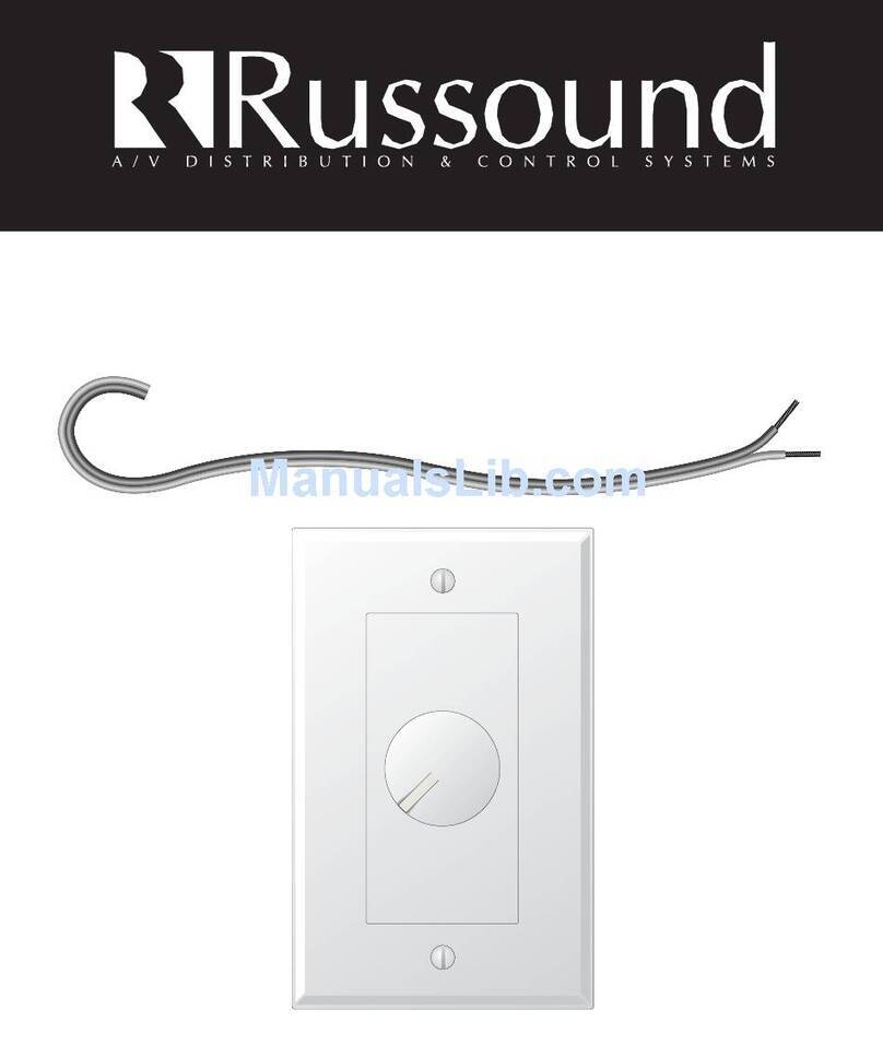
Russound ACP-1DU User manual

5 Forbes Rd. Newmarket, NH 03857, USA
☎ 603.659.5170 • Fax 603.659.5388
e-mail: [email protected]
Come visit us at:
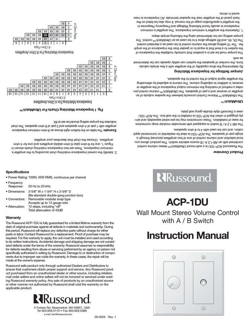
ACP-1DU
Instruction Manual
Technical Information
• Power Rating: 126W, 42W RMS, continuous
• Dimensions: 2-5/8”Wx1-3/4”Hx2-5/8”D
(fits standard double-gang junction box)
• Connectors: Removable screw type
Accepts up to 14 gauge wire
• Attenuation: 12 steps, including “off”
Total attenuation of 43dB
Wiring Instructions (Refer to Diagram)
CAUTION: DO NOT REVERSE THE INPUT AND
OUTPUT CONNECTIONS!
STEP 1:Strip about 1/4” of insulation from the ends of all wires to be connect-
ed to the attenuator. If necessary, twist the exposed conductors to
ensure that no loose strands exist.
STEP 2:Connect the leads from the “A” AMPLIFIER to one of the connectors
labeled INPUT, with the left L+ and L- wires inserted in the appropri-
ately marked openings in the plug.Tighten the screws firmly, making
sure that the exposed bare wire is engaged, not the insulation!
NOTE:To avoid problems with certain types of amplifiers employing bridging
outputs or isolated grounds, the L and R (-) grounds are separate. If a 3
wire system or common ground amplifier is used, the L- and the R-
inputs of the ACP-1 should be jumpered together. If one channel
ground is open, that channel will appear to drop out when the atten-
tuation control is rotated.The L- and the R- connections are placed
adjacent to facilitate such a connection, and also reduce chances for
troublesome shorts.
STEP 3:Connect the leads from the “B” Amplifier to the remaining connector
marked INPUT in the same manner described in STEP 2 and the fol-
lowing note, if applicable.
STEP 4:As outlined in STEP 2, connect the Speaker wires to the connector
labeled OUTPUT, observing channel and polarity identification.
STEP 5:Insert the modular connectors into the appropriate sockets on the PC
board. Make sure that the plugs marked INPUT (from amp) connect
to the sockets marked INPUT (from amp) on the attenuator! Insert
firmly until assembly is fully seated and the locking tabs are engaged.
STEP 6:Install the completed assembly in the junction box. Insert carefully to
avoid excessive strain on the plugs. If necessary, pre-dress the wires for
easier mounting.
L+L
–
R
–
R+
L+L
–
R
–
R+
L+L
–
R
–
R+
AMPLIFIER/RECEIVER
AMPLIFIER/RECEIVER
Connection Diagram
Parts List
(1)Volume Control
(3) Plugs
(4) Mounting Screws
(1) Instruction Limited Warranty
The RussoundACP-1DU is fully guaranteed for a lifetime warranty from the date
of purchase against all defects in materials and workmanship. During this period,
Russound will replace any defective parts and correct any defect in workmanship
without charge for either parts or labor. For this warranty to apply, the unit must be
installed and used according to its written instructions. If service is necessary, it
must be performed by Russound.The unit must be returned to Russound at the
owner’s expense and with prior written permission. Accidental damage and ship-
ping damage are not considered defects under the terms of the warranty.
Russound assumes no responsibility for defects resulting from abuse or servicing
performed by an agency or person not specifically authorized in writing by
Russound. Damage to or destruction of components due to improper use voids
the warranty. In these cases, the repair will be made at the owner’s expense.To
return for repairs, the unit must be shipped to Russound at the owner’s expense,
along with a note explaining the nature of the service required. Be sure to pack in
a corrugated container with at least 3 inches of resilient material to protect the unit
from damage in transit.
Wall Mount
Stereo Volume
Control with
A / B Switch
Product Overview
The Russound ACP-1DU is a wall mount UltraMatchTM stereo volume control
combined with an A / B source selector switch.This product allows you local
selection and volume control of one of two amplifiers (sources) through a sin-
gle pair of speakers, available in a Decora® style double-gang plate.
The volume control is ideal for residential or commercial application. It can be
used with 4 to 8 Ohm speakers.
The A / Bswitch is equipped with screw terminal modular connectors for ease
of installation.These connectors may be pre-wired separately and simply
plugged in.The interlocking feature assures that the connection is safe and
permanent. Connectors are packaged and supplied separately.
UltraMatch™
The UltraMatch™Volume Control you have just purchased con-
nects between the speaker outputs of an amplifier or receiver and a
pair of speakers.The 1X setting allows the volume control to be
used as a standard control.The 2X, 4X, and 8X settings allow it to
be used as an UltraMatch™ control.The UltraMatch™ volume
control provides a method of matching the minimum output
impedance of the amplifier or receiver, in addition to adjusting
volume. It eliminates the need for a speaker selector or imped-
ance matching equipment.The volume is adjusted by attenuating
the amplifier signal output of the control to the speakers. All
RussoundVolume Controls are manufactured using a high-quali-
ty autoformer design which provides long life, excellent frequen-
cy response, no heat build-up, and maximum power transfer
from the amplifier to the speakers. All Russound volume controls
conform to UL Standard 1492 First Edition, and for Canada
Certified to CSA Standard 22.2 No. 1-M94.This certification
assures that your volume control has been designed and tested
for safety.
8X
4X
1X-2X
2X-4X-8X
1X
8X
4X
1X-2X
2X-4X-8X
1X
8X
4X
1X-2X
2X-4X-8X
1X
8X
4X
1X-2X
2X-4X-8X
1X
8X
4X
1X-2X
2X-4X-8X
1X
8X
4X
1X-2X
2X-4X-8X
1X
X1
X2
X4
Jumper
Settings On
Circuit Boards
Russound UltraMatch™ volume controls eliminate the need for
a speaker selector. By determining the drive capability of the
amplifier with a few simple calculations, we can determine the
number of speakers the system can safely operate.
DETERMININGTHE PROPER JUMPER SETTING FOR
IMPEDANCE MATCHING
The jumper must be set in a position that correctly multiplies the
impedance of the system to a level that is equal to or greater than the imped-
ance of the amplifier. The jumper setting can be determined using the follow-
ing simple steps
1. Determine the amplifier's minimum impedance.The amplifier's minimum
impedance is usually found following Wattage and Frequency Response in
the amplifier's specification page of the manual. It may also be listed on the
back panel of the amplifier near the speaker terminals. AC impedance is
measured in ohms.
2. Identify the correct impedance-matching chart according to the amplifier's
minimum impedance.There are two impedance matching charts, one for 8
ohm amplifiers and one for 4 ohm amplifiers. Choose the chart that
describes your amplifier. If your amplifier is 6 ohm stable, use the 8 ohm
chart.
3. Determine the impedance for each pair of speakers by referring to its
manual.
4. Determine the total number of 4 ohm pairs of speakers. (rows on charts)
5. Determine the total number of 8 ohm pairs of speakers. (columns on
charts)
6. Follow the appropriate row and column to determine jumper settings. (ex.
see fig 2)
CONSIDERATIONS
1. Make sure that your amplifier has adequate wattage for the number of
speakers. Watts per channel divided by the number of pairs should equal
or exceed the individual speaker’s minimum wattage requirements.
2. You must use an UltraMatch™ volume control for each pair of speakers.
3. Every jumper setting must be set on the same setting throughout the system.
4. A minimum speaker load of 4 ohms can be connected to the output of
each UltraMatch™ volume control.
EZB CONNECTING BLOCKS
The EZB-1 and EZB-2 connecting blocks are Russound accessories that simplify
connections of multiple volume controls and speaker pairs.The EZB-1 is a neat,
compact wiring device capable of connecting four volume controls to an amplifi-
er's outputs.The EZB-2 expands the EZB-1 to another 4 volume controls.
Multiple EZB-2's can be used to expand the system to sixteen volume controls.
8X
4X
1X-2X
2X-4X-8X
1X
8X
4X
1X-2X
2X-4X-8X
1X
012345678910111213141516
0-1X1X 2X 2X 4X 4X 4X 4X 8X 8X 8X 8X 8X 8X 8X 8X
11X2X2X4X4X4X4X8X8X8X8X8X8X8X8X
22X4X4X4X4X8X8X8X8X8X8X8X8X
34X4X4X8X8X8X8X8X8X8X8X
44X8X8X8X8X8X8X8X8X
58X8X8X8X8X8X8X
68X8X8X8X8X
78X8X8X
88X
Impedance Matching For 4 Ohm Amplifiers
4 Ohm Pairs
8 Ohm Pairs
Fig 2 Impedance Matching Charts For UltraMatch™
012345678
0-1X2X 4X 4X 8X 8X 8X 8X
12X4X4X8X 8X 8X 8X
24X8X8X8X8X
38X8X8X
48X
Impedance Matching For 8 Ohm Amplifiers
8 Ohm Pairs
4 Ohm Pairs
Example:The table to the right shows an 8 ohm minimum impedance amplifier with 1
pair of 4 ohm speakers and 3 pair of 8 ohm speakers.The chart indicates the jumper
setting should be set at 8X
X8

Other Russound Controllers manuals

Russound SMART SELECT VOLUME CONTROL User manual

Russound

Russound SMART SELECT VOLUME CONTROL User manual

Russound WALTX-2 User manual

Russound

Russound WALTX-2 User manual

Russound TBL-75 User manual

Russound

Russound TBL-75 User manual

Russound XLT User manual

Russound

Russound XLT User manual

Russound CA4 User manual

Russound

Russound CA4 User manual

Russound CA 6.4 User manual

Russound

Russound CA 6.4 User manual

Russound LPTX R2 User manual

Russound

Russound LPTX R2 User manual

Russound Sphere E Series User manual

Russound

Russound Sphere E Series User manual

Russound Smart Select Volume Control User manual

Russound

Russound Smart Select Volume Control User manual

Russound ACP-1DU 1 User manual

Russound

Russound ACP-1DU 1 User manual

Russound BSK-2 User manual

Russound

Russound BSK-2 User manual

Russound ALTX User manual

Russound

Russound ALTX User manual

Russound CAS44 User manual

Russound

Russound CAS44 User manual

Russound A-C68 User manual

Russound

Russound A-C68 User manual

Russound CA 4.4pi User manual

Russound

Russound CA 4.4pi User manual

Russound ALTX SC User manual

Russound

Russound ALTX SC User manual

Russound A-BUS A-VC2 User manual

Russound

Russound A-BUS A-VC2 User manual

Popular Controllers manuals by other brands

Actuonix LAC User configuration guide

Actuonix

Actuonix LAC User configuration guide

Hartridge IFT-c Operating and servicing manual

Hartridge

Hartridge IFT-c Operating and servicing manual

VDH Products MC 785-SC operating manual

VDH Products

VDH Products MC 785-SC operating manual

CARLO GAVAZZI VariFlex3 RVLF Series manual

CARLO GAVAZZI

CARLO GAVAZZI VariFlex3 RVLF Series manual

Botex DC-1216 manual

Botex

Botex DC-1216 manual

GESTRA NRR 2-60 Original Installation & Operating Manual

GESTRA

GESTRA NRR 2-60 Original Installation & Operating Manual

FLTR Tekleen GB6 user manual

FLTR

FLTR Tekleen GB6 user manual

DaySequerra NLC5.1ST user manual

DaySequerra

DaySequerra NLC5.1ST user manual

Samsung SM-Z300H/DD user manual

Samsung

Samsung SM-Z300H/DD user manual

Grant Grant Solar GS222020X Installation and servicing instructions

Grant

Grant Grant Solar GS222020X Installation and servicing instructions

GFA 51171735 00002 Guide

GFA

GFA 51171735 00002 Guide

Pinnacle Systems, Inc. NSD-TR-01 Installation and operation manual

Pinnacle Systems, Inc.

Pinnacle Systems, Inc. NSD-TR-01 Installation and operation manual

Promation Engineering P1 A P Series Field manual

Promation Engineering

Promation Engineering P1 A P Series Field manual

Danfoss MCO 305 Design guide

Danfoss

Danfoss MCO 305 Design guide

Rhino Motion EVO quick start guide

Rhino Motion

Rhino Motion EVO quick start guide

Salus PC15V3 quick start guide

Salus

Salus PC15V3 quick start guide

Softmaster MMP compact operating instructions

Softmaster

Softmaster MMP compact operating instructions

Solem BL-AG Quick installation guide

Solem

Solem BL-AG Quick installation guide

manuals.online logo
manuals.online logoBrands
  • About & Mission
  • Contact us
  • Privacy Policy
  • Terms and Conditions

Copyright 2025 Manuals.Online. All Rights Reserved.