Sensata E-100 User manual

E-100 USERS GUIDE
Sensata Technologies Page 1 220808
E-100
24VAC or DC POWERED
ANALOG I/O TO INDUSTRIAL ETHERNET
CONVERTER
Whilst every effort has been taken to ensure the accuracy of this document, we
accept no responsibility for damage, injury, loss, or expense resulting from errors or
omissions, and reserve the right of amendment without notice.
Industrial Interface
This document may not be reproduced in any way without the prior written
permission of the company.
AUG 2022

E-100 USERS GUIDE
Page 2 220808
CONTENTS
1. INTRODUCTION _______________________________________________________4
1.1 Hardware Features _________________________________________________________ 4
1.2 Isolation Details ____________________________________________________________ 4
2. UNPACKING___________________________________________________________4
3. QUICK START GUIDE __________________________________________________5
4. CONNECTIONS ________________________________________________________6
5. CONFIGURING THE SINGLE INPUT E-100 INPUT STAGE __________________8
5.1 Voltage Input: _____________________________________________________________ 9
5.2 Current Input_____________________________________________________________ 10
5.3 Millivolt (mV) Input _______________________________________________________ 11
5.4 Potentiometer Input________________________________________________________ 12
5.5 Thermocouple Input _______________________________________________________ 13
5.6 RTD Input _______________________________________________________________ 14
6. CONFIGURING THE DUAL INPUT E-100 INPUT STAGE ___________________15
6.1 Voltage Input _____________________________________________________________ 16
6.2 Current Input_____________________________________________________________ 17
6.3 Millivolt (mV) Input _______________________________________________________ 18
7. CONFIGURING THE E-100 OUTPUT STAGE______________________________19
8. CALIBRATING THE E-100______________________________________________20
8.1 Main menu _______________________________________________________________ 20
8.2 Input 1 Span and Input 1 Zero values (1. IN1 SPAN and 2. IN1 ZERO)_____________ 21
8.3 Input 2 Span and Input 2 Zero values (3. IN2 SPAN and 4. IN2 ZERO)_____________ 21
8.4 Output Span and Output Zero (5. OUT SPAN and 6. OUT ZERO) ________________ 21
8.5 Display Scaling Values Adjust (7. DSV Cc Pp, 8. DS span, 9. DZ zero)______________ 22
8.6 View Display Scaling Values (10.VIEW DSV) __________________________________ 23
8.7 Linking Outputs to other Parameters (11. OUT Cc Pp, 12. LINK Cc Pp) ___________ 23
8.8 View Link Table (13.VIEW LINK) ___________________________________________ 25
8.9 Burnout Control (14.BURNOUT Cc Pp, 15.LEVEL level, 16.TIME time) ___________ 26
8.10 View Burnout (17.VIEW BURNOUT) ______________________________________ 27
8.11 Serial Protocol (18.MODBUS type)_________________________________________ 27
8.12 Slave Address (19.ADDRESS address) ______________________________________ 27
8.13 Baud Rate (20.BAUD baud) _______________________________________________ 28
8.14 Port Settings (21.PORT port setting)________________________________________ 28
8.15 Character Timeout (22.CH TIME)_________________________________________ 28
8.16 Display Timer (23.DISPLAY display)_______________________________________ 29

E-100 USERS GUIDE
Sensata Technologies Page 3 220808
8.17 Age Select (24.AGE age) __________________________________________________ 29
8.18 Restore Defaults (25.DEFAULTS)__________________________________________ 29
8.19 Modbus 32-bit float format (26.ENDIAN type) _______________________________ 29
9. ISOSLICE BUS________________________________________________________30
10. SERIAL DATA OPTIONS _______________________________________________31
10.1 RS-232___________________________________________ Error! Bookmark not defined.
10.2 RS-485___________________________________________ Error! Bookmark not defined.
10.3 Ethernet _______________________________________________________________ 32
11. ACCESSING THE E-100 DATA __________________________________________33
11.1 Reading Data Values_____________________________________________________ 33
11.2 Reading Scaling and Other Values _________________________________________ 35
11.3 Writing Output Values ___________________________________________________ 39
12. INSTALLATION_______________________________________________________42
13. TROUBLESHOOTING__________________________________________________42
13.1 Incorrect Reading _______________________________________________________ 43
13.2 Sensor Failure __________________________________________________________ 43
14. SPECIFICATIONS (@ 25°C)_____________________________________________43

E-100 USERS GUIDE
Page 4 220808
1. INTRODUCTION
1.1 Hardware Features
The E-100 Ethernet gateway module provides a straightforward method of
interfacing analog and digital process parameters to an RS-232, RS-485, or Ethernet
network. It can accept virtually every type of analog input signal from millivolts to
40Vdc, mA, thermocouples, RTD’s, etc with its universal input option,
Alternatively, it can be fitted to accept two high-level inputs. It can produce 2 types
of analog output: voltage and mA source.
A built-in display allows local monitoring of the individual inputs and outputs and
displays menu options when the unit is configured.
The unit can be powered by a DC voltage between 16 and 36Vdc or 16 and 32Vac.
The instrument is packaged in a compact 22.5mm wide enclosure which can be
mounted on a standard TS35 DIN rail.
The system can be expanded through the use of optional ISO-SLICE slice I/O
modules. These modules connect automatically via the DIN rail-mounted bus
connector, allowing the easy addition and removal of extra I/O.
For data logging applications the unit can be configured with large flash memory
and a real-time clock. This product is called the E-100-LOG.
For applications that require the connection of instruments with an RS-232/RS-485
port to an Ethernet network, the E-PORT variant is available. This has two
communications channels and allows any existing instrument with an RS-232/RS-
485 port to act as a slave on an Ethernet network.
1.2 Isolation Details
The E-100 has full 3 port isolation of 1000V between the Input Stage, Output Stage,
and Power Supply for functional reasons.
2. UNPACKING
The instrument should be carefully inspected for signs of damage that may have
occurred in transit. In the unlikely case that damage has been sustained, DO NOT

E-100 USERS GUIDE
Sensata Technologies Page 5 220808
use the instrument, but please retain all packaging for our inspection and contact
your supplier immediately.
3. QUICK START GUIDE
This example shows how easy it is to configure an E-100 with a 4-20mA Input and
0-10V Output and an Isoslice-2 on the Isoslice Bus.
Before starting, make sure the power supply, inputs, and outputs are
disconnected.
Open the E-100 case and slide out the PCB (see pages 6 and 7)
Set up the input switches to the required input type and range (see pages 8 to 14)
For 4-20mA Input, S1: 2,3,9,10,11,12 on and S2: 1,2,7,8 on (S2 closest to display)
Set up the output switch to mA or voltage (see page 19)
For 0-10V Output, the switch should be on (yellow switch closest to edge of PCB)
Refit the PCB into the housing and fit the complete unit onto the din rail.
Fit the Isoslice unit (configured as channel 2) to the din rail.
Connect up inputs, outputs and power then switch on (see page 6)
The E-100 will communicate with the Isoslice unit automatically at power up.
The Raise button will cycle through the available channels. Channel 1 is the E-100,
and channel 2 is the Isoslice-2. The Lower button cycles through the parameters.
Channel 1 parameter 1 is the Input and parameter 3 is the output. The values on
screen by default represent 0 to 100 %.
Access the main menu by pushing and holding both buttons until OK is displayed.
Calibrate the E-100 input by following the procedure in section 8.2
Calibrate the E-100 output by following the procedure in section 8.4
The scaling of the display input values can be changed by following the procedure
in section 8.5
By default, the output will correspond to the input. To change this, follow the
procedure in section 8.7.
To access the data remotely, refer to Section 11.

E-100 USERS GUIDE
Page 6 220808
4. CONNECTIONS
The E-100 is housed in a compact DIN rail mounting enclosure, with terminals,
arranged in 4 rows. The Communications ports are on the top and the sensor input
terminals and the power supply and analog outputs are on the bottom rows.
The diagram below shows how to connect to an E-100 with a single input, analog
output, and a serial port, either RS-232 or RS-485.
OUTPUT
PSU
SINGLE INPUT
16-36Vdc / 16-32Vac
0V
2
1
+ve
- ve
0-10V 0(4)-20mA
12
10
Voltage Source
Current Source
+ve
- ve
24V Tx Supply
Input: mA, Volts, mV, T/C
4-20mA Sink
3 Wire RTD
4 Wire RTD
125R to 1K
2 Wire Pot
2 Wire RTD
1K to 100K
3 Wire Pot
5
4
3
6
2 Wire
Transmitter
1
2
12
10
4
5
6
3
7Ground
Serial Port
9RS-232 Receive or RS-485 A +ve
8RS-232 Transmit or RS-485 B -ve
9
7
8

E-100 USERS GUIDE
Sensata Technologies Page 7 220808
The diagram below shows how to connect to an E-100 with dual input, an analog
output, and an Ethernet port.
OUTPUT
PSU
DUAL INPUT
16-36Vdc / 16-32Vac
0V
2
1
+ve
- ve
0-10V 0(4)-20mA
12
10
Voltage Source
Current Source
+ve
- ve
24V Tx Supply
Input 1: mA, Volts, mV, TC
4-20mA Sink
5
4
3
6
1
2
12
10
4
5
6
3
RJ45 Ethernet Port
+ve
- ve
Input 2: mA, Volts, mV, TC
2 Wire
Transmitter
24V Tx Supply
4-20mA Sink
2 Wire
Transmitter

E-100 USERS GUIDE
Page 8 220808
5. CONFIGURING THE SINGLE INPUT E-100 INPUT STAGE
See Section 6 for details of how to configure the dual input E-100.
The Single Input E-100 is an extremely versatile device that can support many
different types of input. The unit is configured by turning the power off, selecting
the internal switch settings required, and turning the power back on. Further options
are chosen using the menu system via the display.
To open the E-100, 2 catches just below the outer terminal blocks must be pushed in
gently, one at a time. The front of the case can then be pulled and the unit will
come out of the box.
On a single input E-100 there are 2 switch banks, S1 and S2, a link L201 and a
single switch S4 located inside the E-100 as shown below:
Switch S1, S2 and Link L201 configure the input type and range, and switch S4
configures the output type. The switch settings are explained in the next few pages.
The diagrams refer to switch positions 0 and 1, with 0 being OFF and 1 being ON.
This is illustrated in the picture above.
!
! WARNING !
DO NOT OPEN UNIT OR ADJUST SWITCHES WITH
POWER SUPPLY, INPUT OR OUTPUT CONNECTED
Press here gently
1
1
12
12
Switch S4
Switch S2
Switch S1
10
11
12
ON = 1
OFF = 0
Switch 10 is OFF
Switch 11 is ON
Switch 12 is OFF
OFF
ON
Link L201

E-100 USERS GUIDE
Sensata Technologies Page 9 220808
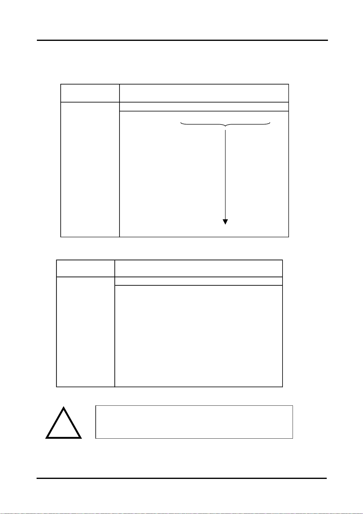
5.1 Voltage Input:
Select the range from the table below and set Switch S1 to the required values.
Then select the required setting from the table below for switch S2.
Voltage
Range
1 2 3 4 5 6 7 8 9 10 11 12
0-1V 0 0 0 0 0 1 0 0 1 1 0 0
0-2V 0 0 0 1 0
0-4V 0 0 1 0 0
0-5V 0 1 0 0 0
0-7.5V 1 0 0 0 0
0-8V 0 0 1 1 0
0-10V 0 1 0 1 0
0-15V 1 0 0 1 0
0-20V 0 1 1 0 0
0-30V 1 0 1 0 0
0-40V 0 1 1 1 0
1-5V 0 1 0 0 1
-5 to +5V 1 1 0 0
1
-10 to +10V 1 1 0 1 0 1 0 0 1 1 0 0
Switch S1
VoltageRange
1 2 3 4 5 6 7 8 910 11 12
0-30V&0-40V
Ranges
0 0 1 1 0 0 1 1 0 0 0 0
0 0 1 0 1 0 1 0 0 0 0 0
AllotherRanges
ListedAbove
SwitchS2
!
! WARNING !
DO NOT OPEN UNIT OR ADJUST SWITCHES WITH
POWER SUPPLY, INPUT OR OUTPUT CONNECTED
E-100 USERS GUIDE
Page 10 220808
5.2 Current Input
Select the range from the table below and set Switch S1 to the required values.
Then select the required setting from the table below for switch S2.
mA Range
1 2 3 4 5 6 7 8 9 10 11 12
0-1mA 0 0 0 0 0 0 0 0 1 1 1 0
0-2mA 0 0 0 1 0
0-4mA 0 0 1 0 0
0-5mA 0 1 0 0 0
0-8mA 0 0 1 1 0
0-10mA 0 1 0 1 0
0-15mA 1 0 0 1 0
0-20mA 0 1 1 0 0
0-30mA 1 0 1 0 0
4-20mA 0 1 1 0 1
4-40mA 0 1 1 1 1
4-30mA 1 0 1 0 1
-5 to +5mA 1 1 0 0 1
-10 to +10mA 1 1 0 1 0 0 0 0 1 1 1 0
Switch S1
mA Range
1 2 3 4 5 6 7 8 9 10 11 12
1 1 0 1 0 0 1 1 0 0 1 0
transmitter
1 1 0 0 0 0 1 1 0 0 0 0
1 1 0 0 1 0 1 0 0 0 0 0
Unipolar Ranges
(e.g. 0-20mA,
4-20mA)
Switch S2
Bipolar Ranges
(e.g.
-10 to +10mA)
Using Internal 24V
Tx Supply for 4 to
20mA
!
! WARNING !
DO NOT OPEN UNIT OR ADJUST SWITCHES WITH
POWER SUPPLY, INPUT OR OUTPUT CONNECTED

E-100 USERS GUIDE
Sensata Technologies Page 11 220808
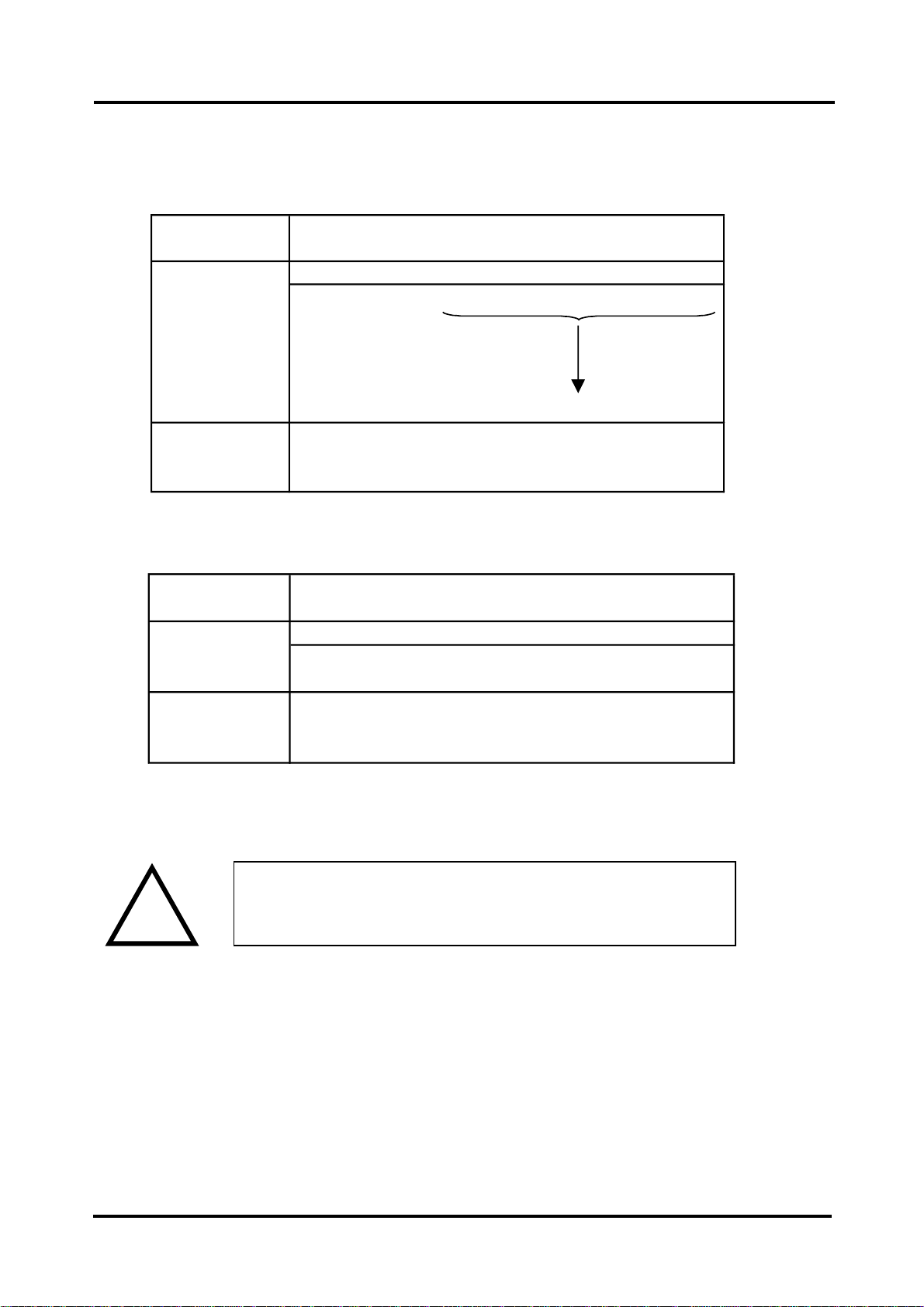
5.3 Millivolt (mV) Input
Select the range from the table below and set Switch S1 to the required values.
And then select the required setting from the table below for switch S2.
mV Range
12345678910 11 12
0-25mV 0 0 0 0 0 0 0 1 1 1 0 0
0-50mV 0 0 0 1
0-100mV 0 0 1 0
0-125mV 0 1 0 0
0-150mV 1 0 0 0
0-200mV 0 0 1 1
0-250mV 0 1 0 1
0-300mV 1 0 0 1
0-500mV 0 1 1 0
0-600mV 1 0 1 0
0-1000mV 0 1 1 1
0-1200mV 1 0 1 1
-125 to +125mV 1 1 0 0
-125 to +1000mV 1 1 1 1 0 0 0 1 1 1 0 0
Switch S1
!
! WARNING !
DO NOT OPEN UNIT OR ADJUST SWITCHES WITH
POWER SUPPLY, INPUT OR OUTPUT CONNECTED
mV Range
12345678910 11 12
010000110000
010010100000
All Unipolar
Ranges (e.g.
0-500mV)
Switch S2
Bipolar Ranges
(e.g.
-125 to +125mV)
E-100 USERS GUIDE
Page 12 220808
5.4 Potentiometer Input
Select the range from the table below and set Switch S1 to the required values.
Then select the required setting from the table below for switch S2.
Please note that to use a 3-wire pot input link L201 must be fitted (see diagram on
page 8 for its location).
Potentiometer
Input
1 2 3 4 5 6 7 8 9 10 11 12
0 1 0 0 1 0 0 1 0 0 0 1
If option fitted:
ALSO FIT LINK L201
0 0 1 1 0 0 1 1 0 0 1 0
3 Wire
Potentiometer
Switch S2
2 Wire
Potentiometer
Potentiometer
Input
1 2 3 4 5 6 7 8 9 10 11 12
2 Wire 0-125R 0 0 0 0 0 0 0 1 1 1 0 1
2 Wire 0-250R 0 0 0 1
2 Wire 0-500R 0 0 1 0
2 Wire 0-625R 0 1 0 0
2 Wire 0-750R 1 0 0 0
2 Wire 0-1K 0 0 1 1 0 0 0 1 1 1 0 1
If option fitted:
3 Wire from
0-1K to 0-100K 0 0 0 0 0 1 0 1 1 1 1 0
Switch S1
!
! WARNING !
DO NOT OPEN UNIT OR ADJUST SWITCHES WITH
POWER SUPPLY, INPUT OR OUTPUT CONNECTED
E-100 USERS GUIDE
Sensata Technologies Page 13 220808
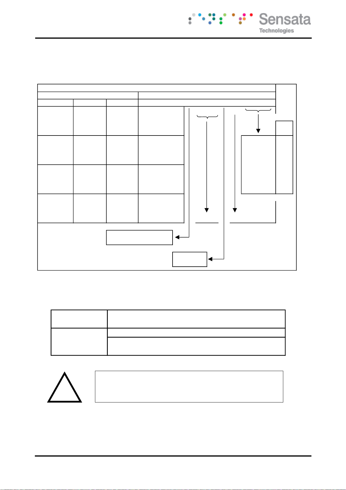
5.5 Thermocouple Input
Select the range from the table below and set Switch S1 to the required values.
Then select the required setting from the table below for switch S2.
Thermocouple
123456789101112
AllRanges010011100000
SwitchS2
Switch
K J R S N E B T 1 2 3 4 5 6 7 8 9 10 11 12
0 to 100 400 to 500 0 to 50 0 0 0 0 0 0 0
0 to 200 400 to 600 0 to 100 0 0 0 1
0 to 400 400 to 800 0 to 200 0 0 1 0
0 to 800 400 to 1200 0 to 400 0 0 1 1
0 to 125 400 to 525 -50 to 50 0 1 0 0 0 0 0
K
0 to 250 400 to 650 -50 to 100 0 1 0 1 0 0 1
J
0 to 500 400 to 900 -50 to 200 0 1 1 0 0 1 0
R
0 to 1000 400 to 1400 -50 to 400 0 1 1 1 0 1 1
S
0 to 150 400 to 550 -100 to 50 1 0 0 0 1 0 0
N
0 to 300 400 to 700 -100 to 100 1 0 0 1 1 0 1
E
0 to 600 400 to 1000 -100 to 200 1 0 1 0 1 1 0
B
0 to 1200* 400 to 1600 -100 to 400 1 0 1 1 1 1 1
T
0 to 175 400 to 575 -200 to 50 1 1 0 0
0 to 350 400 to 750 -200 to 100 1 1 0 1
0 to 700 400 to 1100 -200 to 200 1 1 1 0
0 to 1400** 400 to 1800 -200 to 400 1 1 1 1 0 0 0
Linearisation ON 0
Linearisation off 1
* n/a for types N and E CJC ON 0
** n/a for types K, J, N and E CJC off 1
Temperature Range in °C
Switch S1 for Thermocouple Input
T/C
Type
!
! WARNING !
DO NOT OPEN UNIT OR ADJUST SWITCHES WITH
POWER SUPPLY, INPUT OR OUTPUT CONNECTED

E-100 USERS GUIDE
Page 14 220808
5.6 RTD Input
Select the range from the table below and set Switch S1 to the required values.
And then select the required setting from the table below for switch S2.
RTD
12345678910 11 12
2WireRTD010010010001
3WireRTD010000001001
4WireRTD010000010100
SwitchS2
Range in °C
12345678910 11 12
0 to 100 0 0 0 0 0 0 1 0 0
0 to 200 0 0 0 1
0 to 400 0 0 1 0
0 to 800 0 0 1 1
-50 to 50 0 1 0 0
-50 to 150 0 1 0 1
-50 to 250 0 1 1 0
-50 to 350 0 1 1 1
-100 to 50 1 0 0 0
-100 to 100 1 0 0 1
-100 to 200 1 0 1 0
-100 to 400 1 0 1 1
-200 to 200 1 1 0 0
-200 to 400 1 1 0 1
-200 to 600 1 1 1 0
-200 to 800 1 1 1 1 0 0 1 0 0
RTD linearisation ON 0 PT100 0
RTD linearisation off 1 PT1000 1
RTD 2 or 4 wire 0
RTD 3 wire 1
Switch S1
!
! WARNING !
DO NOT OPEN UNIT OR ADJUST SWITCHES WITH
POWER SUPPLY, INPUT OR OUTPUT CONNECTED

E-100 USERS GUIDE
Sensata Technologies Page 15 220808
6. CONFIGURING THE DUALINPUT E-100 INPUT STAGE
See Section 5 for details of how to configure the single input E-100.
The Dual Input E-100 is an extremely versatile device that can support two inputs.
The unit is configured by turning the power off, selecting the internal switch
settings required, and turning the power back on. Further options are chosen using
the menu system via the display.
To open the E-100, 2 catches just below the outer terminal blocks must be pushed in
gently, one at a time. The front of the case can then be pulled and the unit will
come out of the box.
On a dual input E-100 there are 3 switch banks, S3, S2, and S1, and a single switch
S4 located inside the E-100 as shown below:
Switches S1, S2, and S3 configure the input type and range and switch S4
configures the output type. The switch settings are explained in the next few pages.
The diagrams refer to switch positions 0 and 1, with 0 being OFF and 1 being ON.
This is illustrated in the picture above.
!
! WARNING !
DO NOT OPEN UNIT OR ADJUST SWITCHES WITH
POWER SUPPLY, INPUT OR OUTPUT CONNECTED
Press here gently
1
1
12
12
Switch S4
Switch S2
Switch S1
10
11
12
ON = 1
OFF = 0
Switch 10 is OFF
Switch 11 is ON
Switch 12 is OFF
OFF
ON
1
4
Switch
S3

E-100 USERS GUIDE
Page 16 220808
6.1 Voltage Input
Select the voltage range from the table below for Input 1 or Input 2 or both and set
switches S1, S2 and S3 to the required values.
Note that:
Input 1 is configured with switches 1,3,4,5,6,7 on S1 and switches 1,2,5,6,9,10 on
S2 and switches 3,4 on S3
Input 2 is configured with switches 2,8,9,10,11,12 on S1 and switches 3,4,7,8,11,12
on S2 and switches 1,2 on S3
This allows the inputs to be set up independently so that input 1 could be 0-10V and
input 2 could be 4-20mA with Tx supply if required
Voltage
Range
Input 1 1 3 4 5 6 7 1 2 5 6 9 10 3 4
Input 2 2 8 9 10 11 12 3 4 7 8 11 12 1 2
0-1V 0 1 1 1 0 1 1 1 0 0 1 0 0 0
0-2V 1 0 0
0-2.5V 1 0 0
0-3V 0 1 1
0-4V 0 1 1
0-5V 0 1 1
0-7.5V 0 1 0
0-8V 0 1 0
0-10V 0 1 0
0-15V 0 0 1
0-20V 0 0 1
0-30V 0 0 0
0-40V 0 0 0
1-5V 0 1 1
-2 to +2V
0 0 1 1 0 0 1 1 0 0 0 1 0 0
-5 to +5V 0 1 1
-7.5 to 7.5V 0 1 0
-10 to +10V 0 1 0
-20 to +20V 0 0 1
-24 to +24V 0 0 0
Switch S1
Switch S2
Switch S3
For example
Input 1 is 0-10V: S1 has 3,4,6 on, S2 has 1,2,9 on, S3 has 3,4 off
Input 2 is 0-5V: S1 has 8,9,11,12 on, S2 has 3,4,11 on, S3 has 1,2 off
!
! WARNING !
DO NOT OPEN UNIT OR ADJUST SWITCHES WITH
POWER SUPPLY, INPUT OR OUTPUT CONNECTED

E-100 USERS GUIDE
Sensata Technologies Page 17 220808
6.2 Current Input
Select the current range from the table below for Input 1 or Input 2 or both and set
switches S1, S2 and S3 to the required values.
Note that:
Input 1 is configured with switches 1,3,4,5,6,7 on S1 and switches 1,2,5,6,9,10 on
S2 and switches 3,4 on S3
Input 2 is configured with switches 2,8,9,10,11,12 on S1 and switches 3,4,7,8,11,12
on S2 and switches 1,2 on S3
mA Range
Input 1 1 3 4 5 6 7 1 2 5 6 9 10 3 4
Input 2 2 8 9 10 11 12 3 4 7 8 11 12 1 2
0-1mA 0 1 0 1 1 1 1 1 1 1 1 0 0 0
0-2mA 1 1 0
0-4mA 1 0 1
0-5mA 1 0 1
0-8mA 1 0 0
0-10mA 1 0 0
0-15mA 0 1 1
0-20mA 0 1 1
0-30mA 0 1 0
4-20mA 0 1 1
4-40mA 0 1 1
4-30mA 0 1 1
-5 to +5mA 1 0 0 1 0 1 1 1 1 1 0 0 0 0
-10 to +10mA 1 0 0 1 0 0 1 1 1 1 0 0 0 0
Switch S1
Switch S2
Switch S3
For current inputs an internal 24V Tx supply is available. Select if this is required
from the table below and set switches S1, S2 and S3 to the required values.
24V Tx Supply
mA Range
Input 1 1 3 4 5 6 7 1 2 5 6 9 10 3 4
Input 2 2 8 9 10 11 12 3 4 7 8 11 12 1 2
0-10mA
0 1 0 1 0 0 0 0 1 1 1 0 1 1
0-20mA 0 1 1
4-20mA 0 1 1
4-30mA 0 1 1
4-40mA 0 1 1
Switch S1
Switch S2
Switch S3
For example:
Input 1 is 4-20mA with Tx supply: S1 has 3,6,7 on, S2 5,6,9 on, S3 has 3,4 on
Input 2 is standard 0-20 mA: S1 has 8,11,12 on, S2 has 3,4,7,8,11 on, S3 has 1,2 off

E-100 USERS GUIDE
Page 18 220808
6.3 Millivolt (mV) Input
Select the millivolt range from the table below for Input 1 or Input 2 or both and set
switches S1, S2 and S3 to the required values.
Note that:
Input 1 is configured with switches 1,3,4,5,6,7 on S1 and switches 1,2,5,6,9,10 on
S2 and switches 3,4 on S3
Input 2 is configured with switches 2,8,9,10,11,12 on S1 and switches 3,4,7,8,11,12
on S2 and switches 1,2 on S3
This allows the inputs to be set up independently so that input 1 could be 0-100mV
and input 2 could be 4-20mA with Tx supply if required
mV Range
Input 1 1 3 4 5 6 7 1 2 5 6 9 10 3 4
Input 2 2 8 9 10 11 12 3 4 7 8 11 12 1 2
0-25mV
0 1 0 1 1 0 1 1 1 0 1 0 0 0
0-50mV 1 0 1
0-100mV 1 0 0
0-125mV 1 0 0
0-150mV 1 0 0
0-200mV 0 1 1
0-250mV 0 1 1
0-300mV 0 1 1
0-500mV 0 1 0
0-600mV 0 1 1
0-1000mV 0 0 1
0-1200mV 0 0 1
-250 to +250mV 1 0 0 0 1 1 1 1 1 0 0 0 0 0
-250 to +1000mV 1 0 0 0 0 1 1 1 1 0 0 0 0 0
Switch S2
Switch S3
Switch S1
For example:
Input 1 is 0-50mV: S1 has 3,5,7 on, S2 has 1,2,5,9 on, S3 has 3,4 off
Input 2 is 0-100mV: S1 has 8,10 on, S2 has 3,4,7,11 on, S3 has 1,2 off
!
! WARNING !
DO NOT OPEN UNIT OR ADJUST SWITCHES WITH
POWER SUPPLY, INPUT OR OUTPUT CONNECTED

E-100 USERS GUIDE
Sensata Technologies Page 19 220808
7. CONFIGURING THE E-100 OUTPUT STAGE
If an analog output is fitted the output type is selected with Switch S4.
Output Type
S4 Position
mA Source
Off
Voltage
On
!
! WARNING !
DO NOT OPEN UNIT OR ADJUST SWITCHES WITH
POWER SUPPLY, INPUT OR OUTPUT CONNECTED
Switch S4
OFF
mA source
ON
Voltage

E-100 USERS GUIDE
Page 20 220808
8. CALIBRATING THE E-100
When the unit is shipped the E-100 will be calibrated for the input and output types
and ranges noted on the side label if they are fitted. If this label is blank then the
unit will be calibrated for 4-20mA input(s) and 4-20mA output.
The display is used to show scaled values of the inputs and outputs in the system, or
ON and OFF for digital inputs and outputs. The left button scrolls through the
available channels, and the right button scrolls through the available parameters.
Whilst the button is held down, the channel number is shown on the left of the
screen, and the parameter is shown on the right. The led on the display will flash
every 3 seconds to indicate to the user that the unit is operating. The display can be
configured to remain on all the time or switch off after 15 minutes.
8.1 Main menu
To access the main menu push and hold both buttons until OK is displayed.
These are the main menu options, use the raise and lower buttons to cycle through:
1. IN1 SPAN (sec 8.2) 14. BURNOUT Cc Pp (sec 8.9)
2. IN1 ZERO (sec 8.2) 15. LEVEL level (sec 8.9)
3. IN2 SPAN (sec 8.3) 16. TIME time (sec 8.9)
4. IN2 ZERO (sec 8.3) 17. VIEW BURNOUT (sec 8.10)
5. OUT SPAN (sec 8.4) 18. MODBUS type (sec 8.11)
6. OUT ZERO (sec 8.4) 19. ADDRESS address (sec 8.12)
7. DSV Cc Pp (sec 8.5) 20. BAUD baud rate (sec 8.13)
8. DS span (sec 8.5) 21. PORT port setting (sec 8.14)
9. DZ zero (sec 8.5) 22. CH TIME (sec 8.15)
10. VIEW DSV (sec 8.6) 23. DISPLAY time (sec 8.16)
11. OUT Cc Pp (sec 8.7) 24. AGE age (sec 8.17)
12. LINK Cc Pp (sec 8.7) 25. DEFAULTS (sec 8.18)
13. VIEW LINK (sec 8.8) 26. ENDIAN type (sec 8.19)
Note: menu options 1,2,3,4,5,6 are only available when the input(s) or output are fitted.
To access the sub-menu of one of the main menu options, use raise or lower to cycle
to the option required then push and release both buttons. Change the parameter as
required.
To return to the main menu, push and release both buttons.
To exit from the main menu and return to run mode, press and hold both buttons for
2 seconds until OK is displayed on the screen.
After two minutes of inactivity from the front buttons when the main menu (or a
sub-menu) had been accessed, the unit will automatically return to run mode.
Table of contents
Other Sensata Media Converter manuals

Popular Media Converter manuals by other brands


H&B
H&B TX-100 Installation and instruction manual

Bolin Technology
Bolin Technology D Series user manual

IFM Electronic
IFM Electronic Efector 400 RN30 Series Device manual

GRASS VALLEY
GRASS VALLEY KUDOSPRO ULC2000 user manual

Linear Technology
Linear Technology DC1523A Demo Manual

Lika
Lika ROTAPULS I28 Series quick start guide

Weidmuller
Weidmuller IE-MC-VL Series Hardware installation guide

Optical Systems Design
Optical Systems Design OSD2139 Series Operator's manual

Tema Telecomunicazioni
Tema Telecomunicazioni AD615/S product manual

KTI Networks
KTI Networks KGC-352 Series installation guide

Gira
Gira 0588 Series operating instructions

Lika
Lika SFA-5000-FD user guide