PAGE 2
TT
TT
Table of Contentsable of Contents
able of Contentsable of Contents
able of Contents
Section 1 - GeneralSection 1 - General
Section 1 - GeneralSection 1 - General
Section 1 - General ....................................................................................3....................................................................................3
....................................................................................3....................................................................................3
....................................................................................3
1.1 MOUNTING ................................................................................................31.1 MOUNTING ................................................................................................3
1.1 MOUNTING ................................................................................................31.1 MOUNTING ................................................................................................3
1.1 MOUNTING ................................................................................................3
1.2 WETTED MATERIALS .....................................................................................31.2 WETTED MATERIALS .....................................................................................3
1.2 WETTED MATERIALS .....................................................................................31.2 WETTED MATERIALS .....................................................................................3
1.2 WETTED MATERIALS .....................................................................................3
1.3 OPERATING PRECAUTIONS ............................................................................31.3 OPERATING PRECAUTIONS ............................................................................3
1.3 OPERATING PRECAUTIONS ............................................................................31.3 OPERATING PRECAUTIONS ............................................................................3
1.3 OPERATING PRECAUTIONS ............................................................................3
Section 2 - SpecificationsSection 2 - Specifications
Section 2 - SpecificationsSection 2 - Specifications
Section 2 - Specifications ......................................................................................3.............................3
.............................3.............................3
.............................3
Section 3 - Location RequirementsSection 3 - Location Requirements
Section 3 - Location RequirementsSection 3 - Location Requirements
Section 3 - Location Requirements .......................................................3.......................................................3
.......................................................3.......................................................3
.......................................................3
Section 4 - Sanitary MountingSection 4 - Sanitary Mounting
Section 4 - Sanitary MountingSection 4 - Sanitary Mounting
Section 4 - Sanitary Mounting ...............................................................4...............................................................4
...............................................................4...............................................................4
...............................................................4
Section 5 - Sensor/ Interconnect Cable TSection 5 - Sensor/ Interconnect Cable T
Section 5 - Sensor/ Interconnect Cable TSection 5 - Sensor/ Interconnect Cable T
Section 5 - Sensor/ Interconnect Cable Terminationermination
erminationermination
ermination ........................6........................6
........................6........................6
........................6
5.1 SENSOR CABLE DETAILS5.1 SENSOR CABLE DETAILS
5.1 SENSOR CABLE DETAILS5.1 SENSOR CABLE DETAILS
5.1 SENSOR CABLE DETAILS ........................................................................6........................................................................6
........................................................................6........................................................................6
........................................................................6
5.2 CE TERMINA5.2 CE TERMINA
5.2 CE TERMINA5.2 CE TERMINA
5.2 CE TERMINATION PROCEDURE (FOR CE-TION PROCEDURE (FOR CE-
TION PROCEDURE (FOR CE-TION PROCEDURE (FOR CE-
TION PROCEDURE (FOR CE-ONLONL
ONLONL
ONLY APPLICAY APPLICA
Y APPLICAY APPLICA
Y APPLICATIONS) .............................7TIONS) .............................7
TIONS) .............................7TIONS) .............................7
TIONS) .............................7
5.3 STANDARD TERMINATION PROCEDURE (EXCEPT CE) ..........................................85.3 STANDARD TERMINATION PROCEDURE (EXCEPT CE) ..........................................8
5.3 STANDARD TERMINATION PROCEDURE (EXCEPT CE) ..........................................85.3 STANDARD TERMINATION PROCEDURE (EXCEPT CE) ..........................................8
5.3 STANDARD TERMINATION PROCEDURE (EXCEPT CE) ..........................................8
5.4 INTERCONNECT CABLE DETAILS........................................................................95.4 INTERCONNECT CABLE DETAILS........................................................................9
5.4 INTERCONNECT CABLE DETAILS........................................................................95.4 INTERCONNECT CABLE DETAILS........................................................................9
5.4 INTERCONNECT CABLE DETAILS........................................................................9
Section 6 - TSection 6 - T
Section 6 - TSection 6 - T
Section 6 - Troubleshootingroubleshooting
roubleshootingroubleshooting
roubleshooting ...................................................................10...................................................................10
...................................................................10...................................................................10
...................................................................10
6.1 CHECKING THE SENSOR ...............................................................................106.1 CHECKING THE SENSOR ...............................................................................10
6.1 CHECKING THE SENSOR ...............................................................................106.1 CHECKING THE SENSOR ...............................................................................10
6.1 CHECKING THE SENSOR ...............................................................................10
Section 7 - Ordering MatrixSection 7 - Ordering Matrix
Section 7 - Ordering MatrixSection 7 - Ordering Matrix
Section 7 - Ordering Matrix ..................................................................10..................................................................10
..................................................................10..................................................................10
..................................................................10
Section 8 - WSection 8 - W
Section 8 - WSection 8 - W
Section 8 - Warranty and Rarranty and R
arranty and Rarranty and R
arranty and Return Statementeturn Statement
eturn Statementeturn Statement
eturn Statement .....................................11.....................................11
.....................................11.....................................11
.....................................11
FIGURESFIGURES
FIGURESFIGURES
FIGURES
FIGURE 4-1FIGURE 4-1
FIGURE 4-1FIGURE 4-1
FIGURE 4-1 SANITARY MOUNTING DETAILS ....................................................5SANITARY MOUNTING DETAILS ....................................................5
SANITARY MOUNTING DETAILS ....................................................5SANITARY MOUNTING DETAILS ....................................................5
SANITARY MOUNTING DETAILS ....................................................5
FIGURE 5-1FIGURE 5-1
FIGURE 5-1FIGURE 5-1
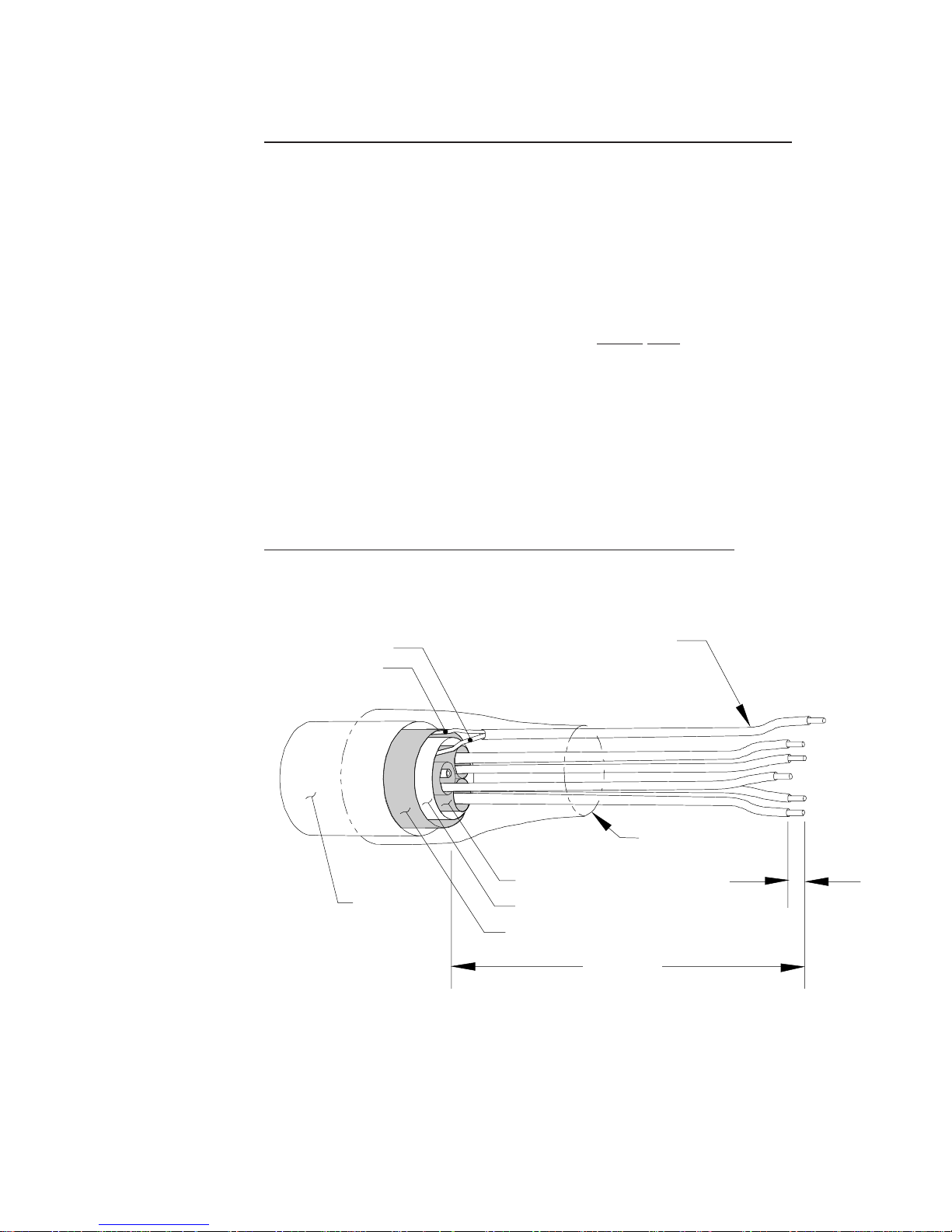
FIGURE 5-1 STANDARD TERMINATION DETAILSSTANDARD TERMINATION DETAILS
STANDARD TERMINATION DETAILSSTANDARD TERMINATION DETAILS
STANDARD TERMINATION DETAILS (EXCEPT CE)................................7(EXCEPT CE)................................7
(EXCEPT CE)................................7(EXCEPT CE)................................7
(EXCEPT CE)................................7
FIGUREFIGURE
FIGUREFIGURE
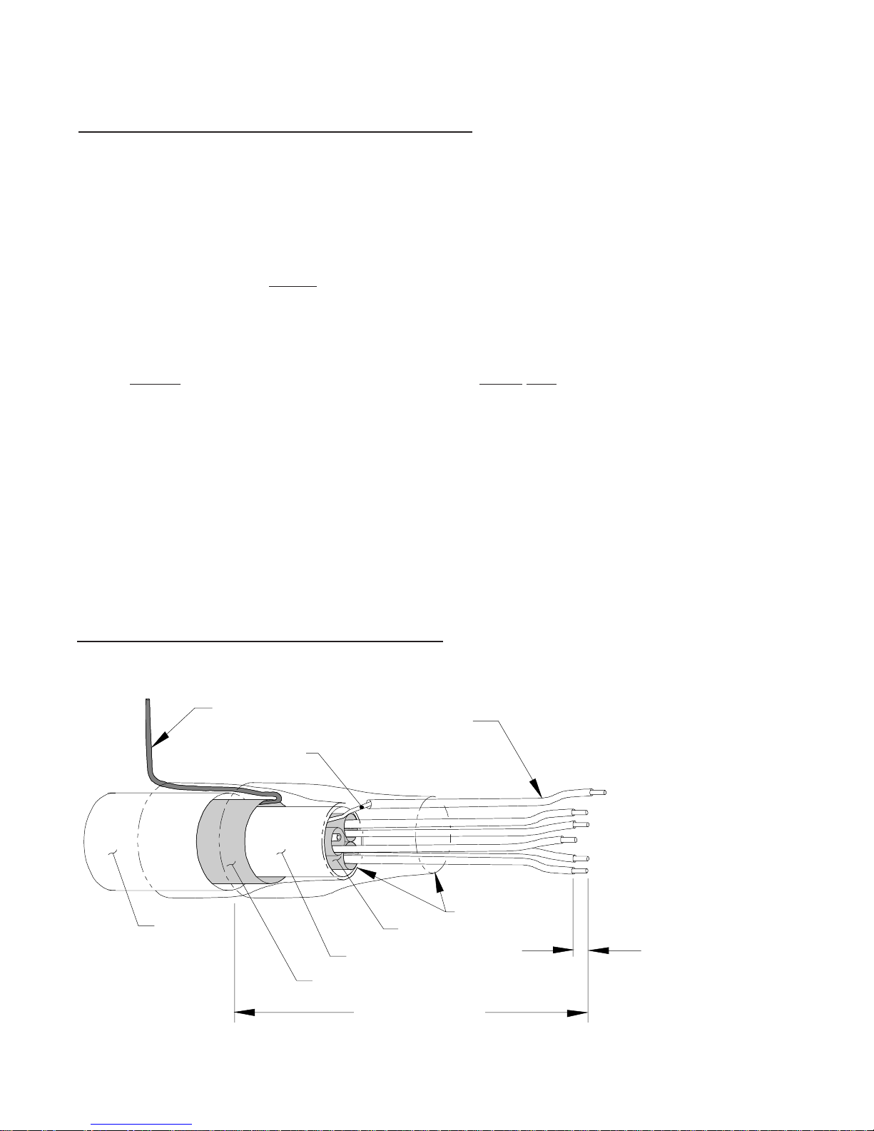
FIGURE 5-25-2
5-25-2
5-2 CE TERMINACE TERMINA
CE TERMINACE TERMINA
CE TERMINATION DETTION DET
TION DETTION DET
TION DETAILS (FOR CE-AILS (FOR CE-
AILS (FOR CE-AILS (FOR CE-
AILS (FOR CE-ONLONL
ONLONL
ONLY APPLICAY APPLICA
Y APPLICAY APPLICA
Y APPLICATIONS) .................8TIONS) .................8
TIONS) .................8TIONS) .................8
TIONS) .................8
FIGURE 5-3FIGURE 5-3
FIGURE 5-3FIGURE 5-3
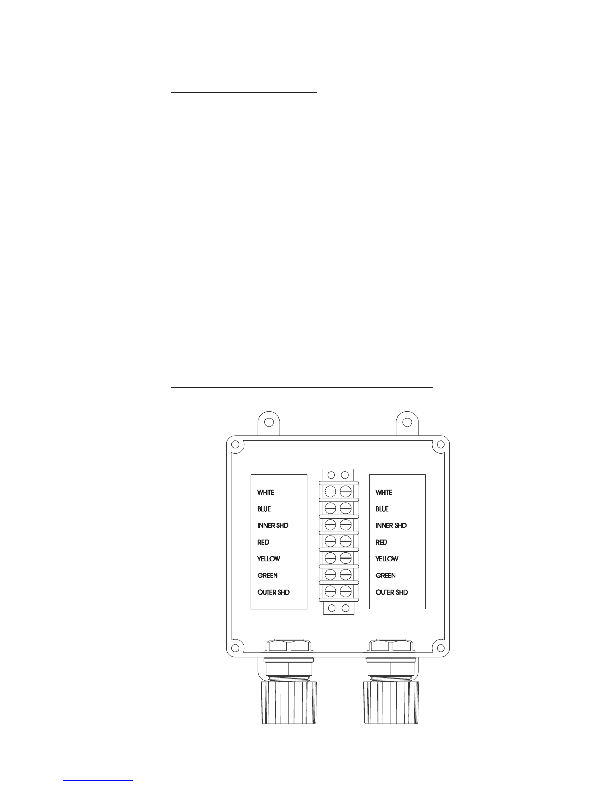
FIGURE 5-3 INTERCONNECT CABLE / JUNCTION BOX TERMINATIONS ...................9INTERCONNECT CABLE / JUNCTION BOX TERMINATIONS ...................9
INTERCONNECT CABLE / JUNCTION BOX TERMINATIONS ...................9INTERCONNECT CABLE / JUNCTION BOX TERMINATIONS ...................9
INTERCONNECT CABLE / JUNCTION BOX TERMINATIONS ...................9