3. OPERATING INSTRUCTIONS
Operation
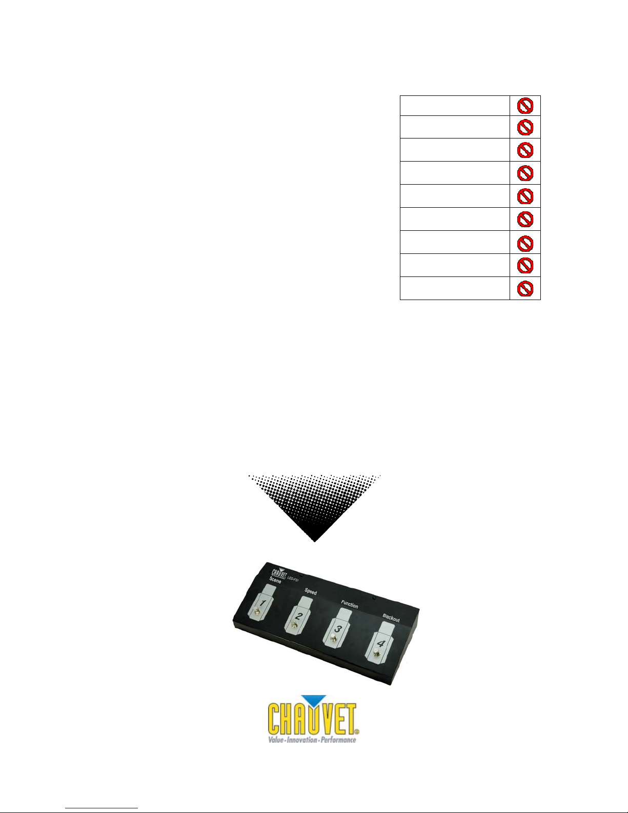
Scene Switch (1)
This button allows the user to cycle through the stand-alone programs in the COLORstrip™ fixture. You can click the button once for
each of the programs to cycle through slowly, or hold down the button to cycle through the programs at an accelerated rate. For a
detailed description of the programs built into the unit, please consult the COLORstrip™ manual.
Speed Switch (2)
This button allows users to select the run speed of the selected program. The button may be clicked once to slowly cycle through
individual speeds, or held down to increase speed at an accelerated rate. The speed can be adjusted from 000 to 100, with two
separate corresponding values, which are dependent upon the program being accessed.
For programs A001-A007, the speed increases as value increase, with 99 being the fastest value, and 100 representing a “blackout”
when no sound is present, and a flash to sound when present.
For programs A008-A011, a speed setting between A000-A050 remains a static speed increase, with values 051-100 having a new
feature. These values are designed as sound active, with an auto-default to an automatic speed in the absence of sound. For
example, if the unit is set to a speedof 100, and the microphone is no longer detecting sound, the unit will continue the program at the
fastest possible speed. The same fixture and program set at a speed of 051, would run through the program much more slowly, when
sound is absent, the P value will adjust speed, while the F value adjusts flash rate.
For programs A012-A020, a speed setting between A000-A050 remains a static speed increase, with values 051-100 having a new
feature. These values are designed as sound active, with an auto-default to an automatic speed in the absence of sound. For
example, if the unit is set to a speedof 100, and the microphone is no longer detecting sound, the unit will continue the program at the
fastest possible speed. The same fixture and program set at a speed of 051, would run through the program much more slowly, when
sound is absent.
Program A021 will color mix by adjusting the appropriate value. P (red), F (green), and C (blue).
Program A022 will begin a color fade, the speed of which can be adjusted from 000-100.
Program A023 is an auto-run program and is not adjusted by the speed function.
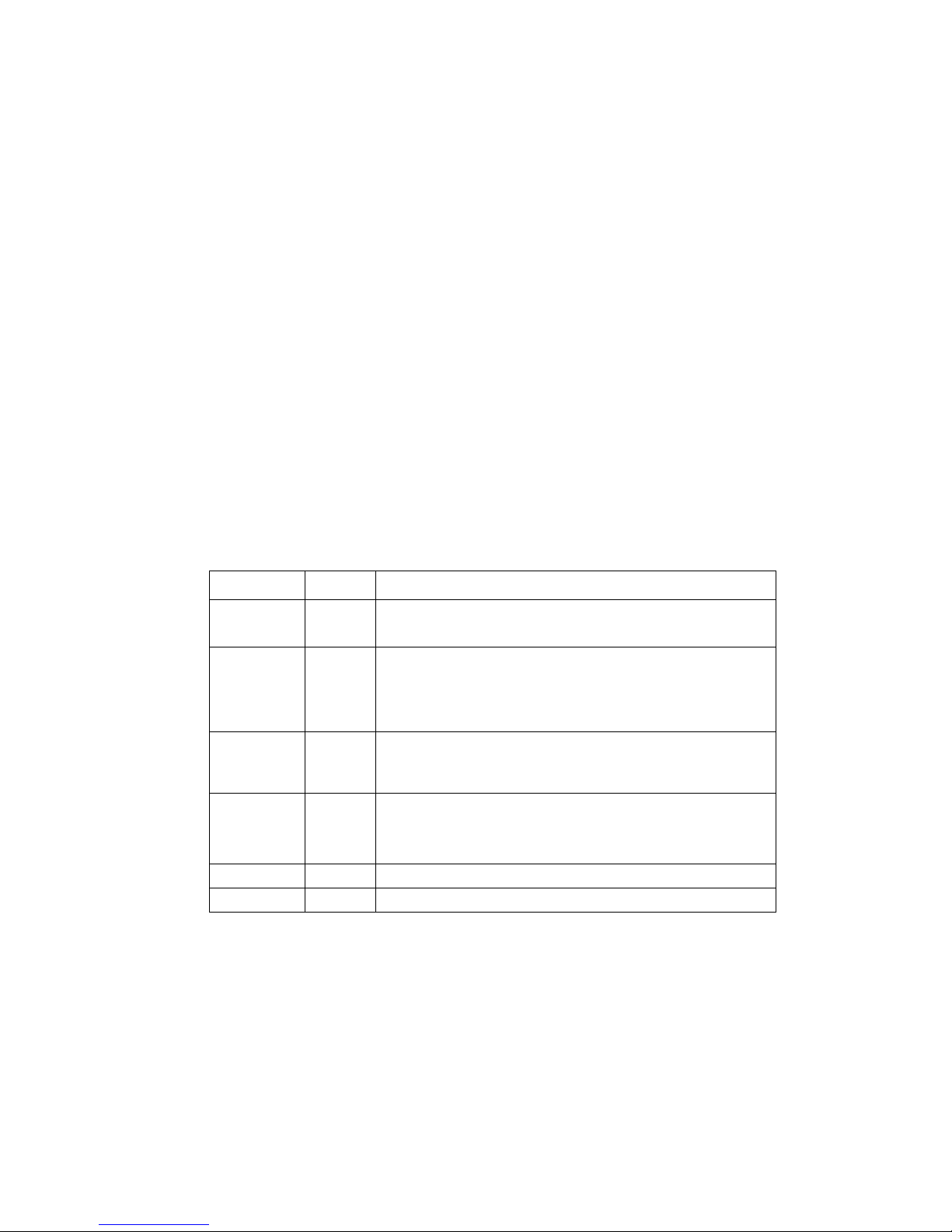
Program Value Additional Functions
A001 – A007 000-099
100
Speed increases as value increases (Flash Speed)
Flash with sound, blackout without sound
A008 – A011
000-050
051-100
Static speed increase as value increases
Sound active, default to auto when no sound present, with speed determined by
numerical value.
P= Speed, F= Flash Rate
A012 – A020 000-050
051-100
Static speed increase as value increases
Sound active, default to auto when no sound present, with speed determined by
numerical value.
A021 000-100
P = Red 000-100
F= Green 000-100
C= Blue 000-100
A022 000-100 Color Fade
A023 000-100 Auto Run
*Note values appear on COLORstrip display only
Function Switch (3)
This button allows users to quickly place the COLORstrip™ unit into Sound-Active mode. To exit the sound
function, use the Scene Switch (1) to select the program you wish to activate.
Blackout Switch (4)
This button allows users to blackout the fixture, disabling all output from the unit. If the button is clicked with
the unit already in blackout mode, it will immediately resume the last running program.
LED-FS1 6 10/17/2007 1:02 PM