SENSIT Technologies SPOD User manual

1
SENSIT SPOD Sensor Operation Manual and
Configuration Guide
Version 1.0, August 12, 2019

2
SPOD Sensor Overview
General
Overview
Parameter
Weight
Base unit: 6.75 lbs
Dimensions
Fully assembled with anemometer and antenna
•D x W x H (6” x 8” x 16”)
Mounting
Attached mounting flanges
Voltage Requirements
18V – 24V DC Charging (wired adapter or solar panel)
Current Requirements
2A max current draw when charging
Operating Runtime
3-5 days battery backup 1
Operating Temp
-10°C to 50°C 2
Data Outputs
•Digital wired output (3.3V TTL - USB)
•Wireless (4G IoT Cellular Included) 2
•Optional analytics on server 4
•SD card data backup 5

3
Notes:
1. Battery backup time depends on run mode and frequency of transmission.
2. Limited by lithium ion charging temperature. Lower temperature operation
will require external or internal heating to maintain sufficient battery
temperature for charge acceptance. Contact the manufacturer for more
information.
3. Requires SIM card and suitable data plan on AT&T or T-mobile. Verizon
service is pending
4. Cloud based analytics can be developed with additional contract
5. When removing SD card to obtain data, it is recommended to power off the
sensor box prior to reinserting the SD card to avoid possible errors. If the
system stops responding or any SD errors are observed after inserting an
SD card, power down the sensor and turn back on.

4
Sensors
Overview
Parameter
Default PID Detection Range
10 ppb – 2 ppm1
Default PID Lamp Energy
10.6 eV2
Target PID Accuracy
+/- 20 ppb min or 10%3,4
Response Time
5-10 seconds5,6
Expected Lamp Life
1 year+
Notes:
1. VOC range reference to isobutylene. Additional PID sensors available with
identical form factors if higher concentrations are necessary.
2. Additional PID sensors available with identical form factors if different lamp
energies are required.
3. Factory calibration conducted with 1ppm isobutylene and ultra zero air
4. PID Sensors are sensitive to high amounts of humidity and may rail at the
upper output if humidity is excessive. The SPOD contains an internal sensor
heater to minimize humidity interference.
5. If the unit has been off for an extended period of time, it could take several
minutes to an hour for the PID readings to drop to normal operating
conditions depending on storage conditions. This stabilization may
temporarily interfere with VOC detection.
6. Exposure to very high levels of VOCs may saturate the detector for several
minutes to an hour

5
Cellular Specifications
Overview
Parameter
Network Technology
4G/2G1
Carrier
AT&T and T-mobile2
Transport Layer
TCP
Internet Layer
IP
Application Layer
HTTP and MQTT
Data Transfer Method
HTTP POST or MQTT Topics
HTTP Content Type
application/x-www-form-urlencoded
HTTP Body Field Identifiers
&ID, &MODULE, &STAT, &DATA
MQTT Content Type
JSON
MQTT Tags
“deviceId”, “time”, “iodb”
Post Location
Adjustable in Menu
APN
Adjustable in Menu
TLS/SSL
HTTPS and MQTTS with server
authentication
3
Notes:
1. 4G CAT M1 and NB-IoT
2. Modem is pending Verizon certification
3. Client authentication possible with additional development.

6
Sensor Exterior Features (Front Exterior)
7
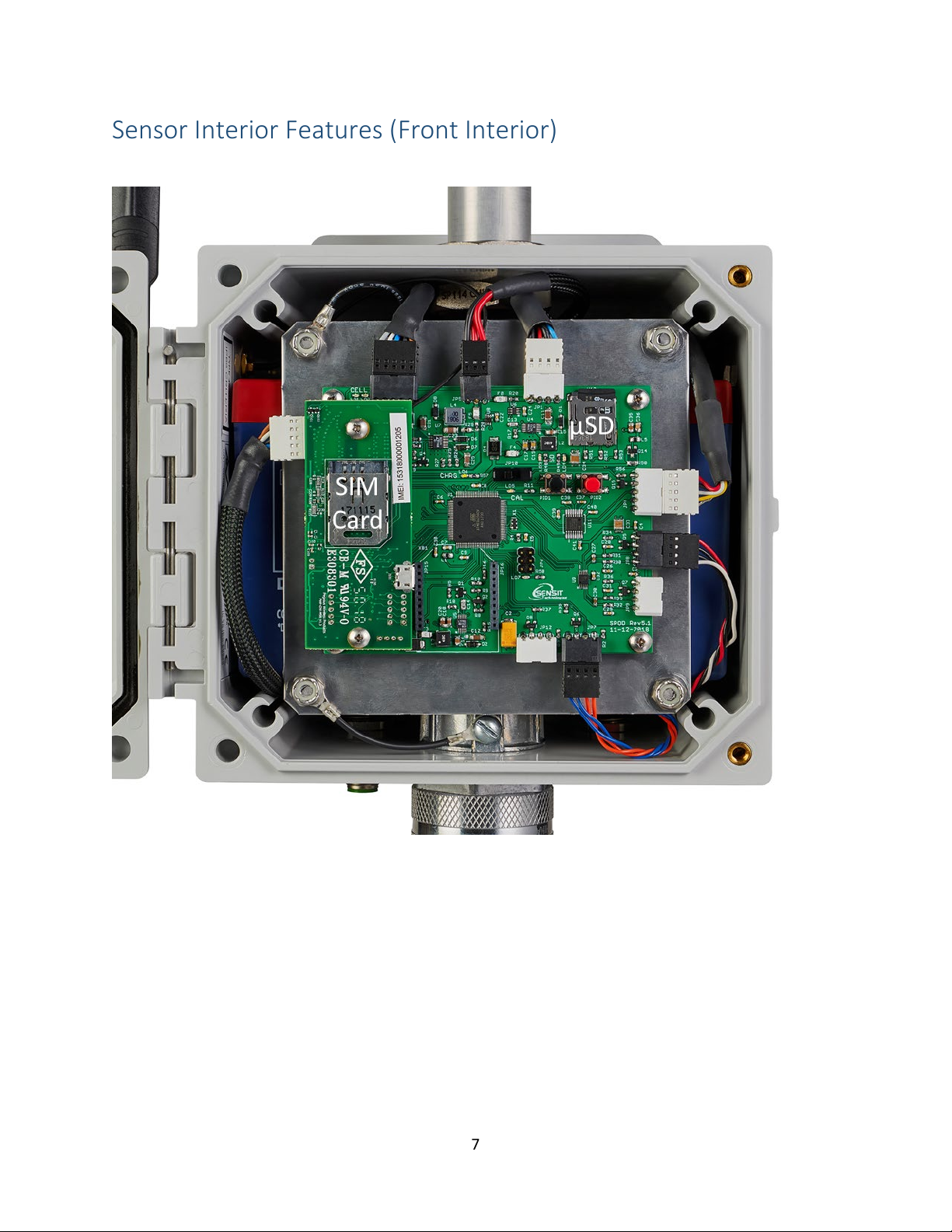
Sensor Interior Features (Front Interior)
8
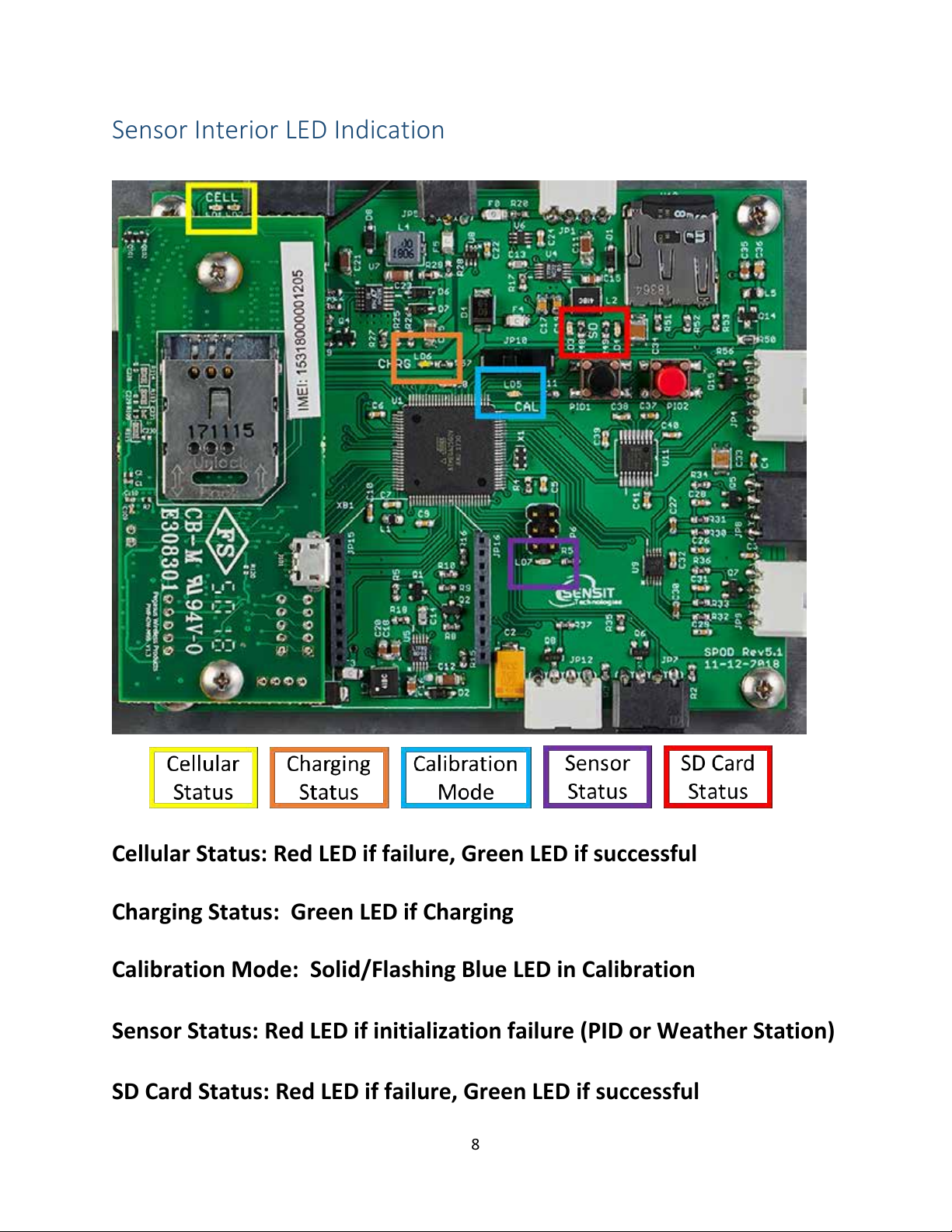
Sensor Interior LED Indication
Cellular Status: Red LED if failure, Green LED if successful
Charging Status: Green LED if Charging
Calibration Mode: Solid/Flashing Blue LED in Calibration
Sensor Status: Red LED if initialization failure (PID or Weather Station)
SD Card Status: Red LED if failure, Green LED if successful

9
Quick Start Deployment Guide (USB Cable & Computer)
It is recommended to use a computer and the supplied USB cable when setting up
the sensor unit to verify the operation of the sensors, system output, and cellular
data connectivity (if applicable).If no cable and computer are available, please
see the next page.
Unpack the sensor unit and check for any physical damage or obstructions at the
sensor openings. Open enclosure cover and check for any loose or damaged
components. Make sure all wires are securely fastened as shown in the internal
sensor view on page 7.
1) Hook up USB cable sensor and initialize terminal connection. Power on unit
and verify that the SD card was detected and initialized.
2) Verify the sensor outputs are reasonable or trending toward reasonable
values keeping in mind the stabilization time for sensors that have been
powered off or exposed to high VOC concentrations. Additionally, it may
take up to 30 seconds for the ultrasonic anemometer to report valid
environmental data. For information on USB headings and field
identification, please see page 10.
3) When installing orient the weather sensor such that it is pointing North.
Failure to do this will result in arbitrary wind direction. The North direction
is indicated with a notch on the ultrasonic anemometer base. See page 11
for anemometer instructions. Never rotate the anemometer from the top
or severe damage will occur.
4) After verifying functionality remove the USB cable. If planning to run in
USB mode, install a power adapter or a solar panel for long term
deployment applications. Otherwise, power cycle the SPOD, then install a
power adapter or a solar panel for long term deployment applications.

10
Quick Start Deployment Guide (No Computer)
Unpack the sensor unit and check for any physical damage or obstructions at the
sensor openings. Open enclosure cover and check for any loose or damaged
components. Make sure all wires are securely fastened as shown in the internal
sensor view on page 7 and refer to the LEDs indicated on page 8.
1) Power on unit. The illuminated switch should turn on. If the switch does
not illuminate, inspect all wiring connections and charge battery.
2) Verify that the SD card was detected and initialized with the SD status LEDs
3) Verify the absence of sensor errors with sensor status LED.
4) If HTTP or MQTT protocol is selected verify successful initialization after
startup with Cellular status. If PERIODIC protocol is used wait for required
amount of time before cellular post.
5) If power is hooked up, wait for 1 minute after power up to verify the
charging status LED is illuminated. Please note that if the battery is
completely full the charging status LED will not illuminate.
6) When installing orient the weather sensor such that it is pointing North.
Failure to do this will result in arbitrary wind direction. The North direction
is indicated with a notch on the ultrasonic anemometer base. See page 11
for anemometer instructions. Never rotate the anemometer from the top
or severe damage will occur.
7) After initialization is complete the illuminated switch will flash once per
second to indicate normal operation

11
USB Output Headings and Description
USB Heading
Description
Units/Format
DATE
Local Date and Time
MM/DD/YY HH:MM:SS (24H)
PID1
Field 1, Sensor 1 VOC
PPB
Field 2, Sensor 1 Raw
mV
PID21
Field 1, Sensor 2 VOC
PPB
Field 2, Sensor 2 Raw
mV
T
Temperature
°C
RH
Relative Humidity
%
P
Pressure
mBar
WS
Wind Speed
mph
WD
Wind Direction
Degrees
TC
Field 1, Sensor 1 Temp
Arb Units
Field 2, Heater 1 Output
Arb Units
Field 3, Sensor 2 Temp1
Arb Units
Field 4, Heater 2 Output1
Arb Units
BATT
Battery Voltage
Volt
CHRG
Charging Current
mA
RUN
Operating Current
mA
TRIG
Field 1, Trigger Flag
0 or 1 if threshold exceeded
Field 2, Trigger Counter
Adjustable
Field 3, Sample Flag
0 or 1 if sample acquired
LAT2
GPS Latitude
Degrees
LON2
GPS Longitude
Degrees
Notes:
1. The control circuit board is designed to support a second sensor.
Additional parameters will show up in the output if a dual sensor unit is
configured by the factory.
2. GPS is not enabled on all units. Please contact Sensit to enable GPS.

12
Ultrasonic Anemometer Mounting Instructions

13
Tripod Setup and Installation (Optional)
1) Remove protective rubber feet if installing outdoors
2) Install pole on tripod. Pole mounting attachment may differ from image
below.
3) Set leg height of tripod and spread legs with a minimum of 30° from
perpendicular
4) For added stability in high wind or long-term deployments place sandbags
against all legs
Catch tab with
bag to hold down

14
5) Use the shorter ¼” long screw to attach pole mount to back of SPOD
6) Use the longer 1 ¼” long screw + nut to tighten on pole
7) Tighten sufficiently to prevent rotation
8) Place SPOD as far up as possible on pole to avoid blocking anemometer
Note: The images below are used for reference. SPOD appearance will differ
from image below.

15
Solar Panel Setup and Installation (Optional)
1) Lift up on side with 2 knobs to unfold panel
2) Fold down angular supports on both sides and remove 2 knobs on bottom
3) Reattach knobs vertical angular supports on both sides (flat washer, lock
washer, wing nut)

16
4) Place solar panel on ground and fasten to ground or add ballast if possible
(recommended to avoid wind damage and theft)
5) Avoid shadowing on panel as much as possible as this will drastically reduce
panel output power and efficiency
6) Route cable to SPOD unit
7) Plug cable into SPOD “Power/USB” connection
8) Power on SPOD unit
Note: Alternative solar mounts and solar panel extension cables can be purchased
from Sensit. Please contact Sensit for more information if your application
requires an alternative solar mounting setup.

17
USB Communication & Configuration Mode (Sensor)
The SPOD units allow for the reconfiguration of several parameters pertaining to
the operation of system. Adjustment of these parameters is only accessible for a
short period of time after powering on the sensor (~10s). These parameters are
stored in non-volatile memory and are retained during subsequent power cycling.
Documentation of these parameters is listed below.
Required Components:
-SPOD Unit
-USB data cable
-Computer with a serial port terminal software program (e.g. CoolTerm)
Sensor Quickstart Instructions
1) Connect the USB cable to the SPOD and computer and establish the
communication link in the terminal software.
2) Turn on power switch and observe initialization process. After initializing the
microcontroller and printing SPOD information, the system will system will
prompt the user to:
“Enter Configuration Mode? (YES)”
3) Configuration mode allows access to configuration settings and system
settings. To enter configuration mode type Yes at the prompt and hit enter.
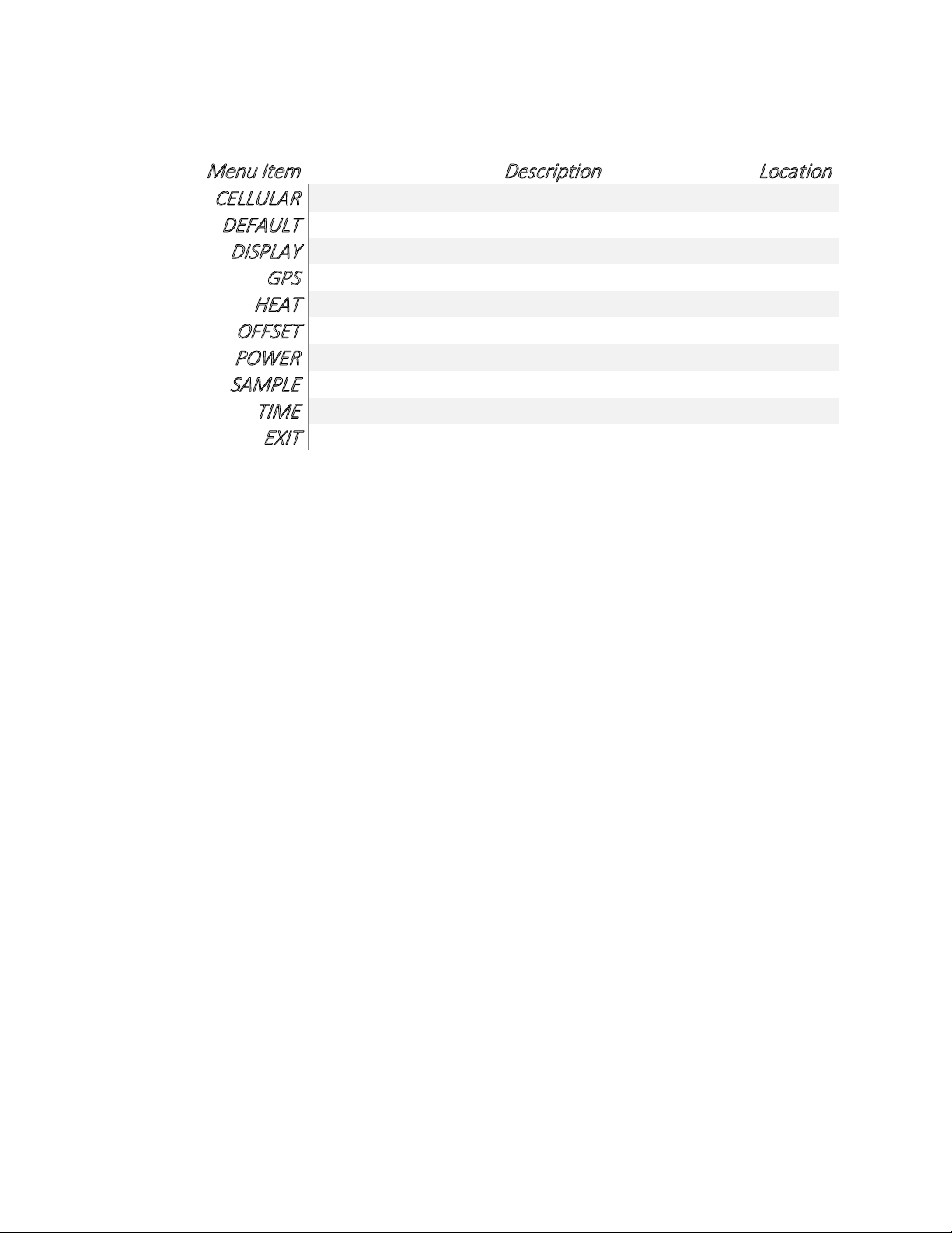
The menus are all text-based and easy to follow. The following list contains all
the adjustable within the menu:
18
Menu Item
Description
Location
CELLULAR
Common settings
Root Menu
DEFAULT
System Default Settings
Root Menu
DISPLAY
Prints Current Settings
Root Menu
GPS
GPS Settings
Root Menu
HEAT
Sensor Heater Settings
Root Menu
OFFSET
Sensor Offset Setting
Root Menu
POWER
Power Settings
Root Menu
SAMPLE
Trigger Sample Settings
Root Menu
TIME
Time Settings
Root Menu
EXIT
Exit Menu
Root Menu
Detailed Root Menu Information
Cellular: Contains all settings associated with the cellular modem. This is
required for communication with any online servers.
Default: Resets all options to the factory default. Not recommended without
consulting Sensit.
Display: Displays all current settings in the terminal window. An example print
out is shown below. Please not that system settings may differ from device to
device depending on the application.
System DATE,08/09/19 11:57:06
Sensor ID: SPOD00100
Battery Voltage: 13.74
Power Source: AC Power
Output Mode: Streaming
Communication Mode: Cellular
Network Selection: Automatic
Cellular Protocol: MQTT v3.1.1 with TLS
Publish Topic: "devices/SPOD00100/messages/events/"
Subscribe Topic:
Output Data Rate: 10
Cellular Output Ratio: 120

19
Server Address: sensit-test-hub.azure-devices.net
Access Point Name: zipitwireless.com.attz
GPS Mode: Interval
Sensor Heater: Enabled
Temp Set: 15
Dew Point Control: Disabled
Humidity Threshold: 80
Temp Set: 15
PID1 Offset Value (ppb): 0.00
Sample Trigger Value (ppb): 500
Trigger Average Time (sec): 10
Sample Collection Time (sec): 30
GPS: “ENABLE” or “DISABLE” the GPS. Depending on the cellular data protocol
and output mode, the user may be presented with additional options. If cellular
output is disabled or if PERIODIC protocol is selected the GPS mode will default to
SINGLE (see below). If cellular output is enabled and MQTT or HTTP protocol are
enabled the user can select between the following GPS settings:
“CONSTANT”: GPS is always on and fixing position (Highest power draw)
“INTERVAL”: GPS turns on at and interval determined by “RATIO”x”ODR”
“SINGLE”: GPS turns on at power up and remains off until system is reset
HEAT: Adjust “CONSTANT” or “HUMID” heat settings. The “CONSTANT” setting
means that the sensor heater is on at all times if enabled. The “HUMID” setting
means that the sensor heater is on only if humidity exceeds a predefined
threshold. If either option is enabled the user will be prompted to adjust the
heater setpoints and for the “HUMID” option the user will be prompted to adjust
the humidity set point. Both options could be enabled simultaneously to produce
different heater setpoints depending on the humidity level. “CONSTANT” heat is
enabled by default at 15°C above ambient.
OFFSET: Adjust the baseline of the PID sensor up or down by a constant value.
OUTPUT: This menu contains settings that modify the output characteristics of
the sensor.

20
POWER: Select “SOLAR” and “AC” power. If “SOLAR” is selected the unit will try
to charge the batteries whenever power is present. If “AC” is selected the system
will maintain the battery voltage in the middle of its range to extend battery life.
It is very important that “SOLAR” is selected for remote power application.
SAMPLE: Control the behavior of the auxiliary port. The port is configured to
supply power to a valve to trigger sample collection if the PPB reading exceeds a
predefined threshold for a predefined amount of time.
TIME: Set the system date and time. If cellular mode is enabled this will happen
automatically when the device connects. Note that the initial data may have the
wrong date and time until the clock adjusts.
EXIT: Leave the root menu and starts system operation
Detailed Cellular Menu Information
Menu Item
Description
Location
APN
Carrier APN Setting
Cellular Menu
CREDENTIALS
MQTT Username and Password
Cellular Menu
HOST
Server Location Address
Cellular Menu
NETWORK
Cellular Network Configuration
Cellular Menu
PROTOCOL
Data Transfer Protocol
Cellular Menu
RATIO
Number of Samples to Buffer
Cellular Menu
SIGNAL
Apply settings and check signal
Cellular Menu
TLS
Activate TLS, Load Server Cert
Cellular Menu
TOPICS
MQTT Topics
Cellular Menu
EXIT
Exit Cellular Menu
Cellular Menu
APN: Set the required APN for data access on the installed sim card. Please note
that the APN text entry might be case sensitive
CREDENTIALS: Set the require USERNAME and PASSWORD require for MQTT
data access.
Other manuals for SPOD
1
Table of contents
Other SENSIT Technologies Accessories manuals

Popular Accessories manuals by other brands

Eurotramp
Eurotramp KIDS TRAMP Product and service information

PCB Piezotronics
PCB Piezotronics 351B11 Installation and operating manual

Lion Precision
Lion Precision LRD5100 Tear-Tape user guide

INNOBIZ
INNOBIZ Lilia Instructions for use

Harbor Freight Tools
Harbor Freight Tools 38335 instruction manual

YOKOGAWA
YOKOGAWA FU20-FTS instruction manual


