Dinel CLS-23 User manual

Read carefully the instructions published in this manual before the rst use of the sensor. Keep the manual
at a safe place. The manufacturer reserves the right to implement changes without prior notice
INSTRUCTION MANUAL
průmyslová elektronika
CapaCitive level sensors Cls 23
Microlectra bv.
www.microlectra.nl
Microlectra bv.
Augustapolder 12. 2992 SR Barendrecht. The Netherlands.
www.microlectra.nl [email protected]

CONTNT
. afety.........................................................................................................................................4
. acing transportation and storage ..........................................................................................4
. rief............................................................................................................................................5
. eatures of variants ...................................................................................................................5
. imensional drawings................................................................................................................6
. ounting recommendation.........................................................................................................7
. lectrical connection ..................................................................................................................9
. ensor setting ............................................................................................................................11
. tatus signaliation ....................................................................................................................11
. ccessories..............................................................................................................................12
. rder code ...............................................................................................................................13
. orrect specication eamples ................................................................................................13
. afety protections compatibility and eplosion proof .............................................................14
. se manipulation and maintenance........................................................................................14
. eneral conditions and warranty .............................................................................................14
. aring of labels......................................................................................................................15
. pecications...........................................................................................................................16
CLS23 Dinel
4
All operations described in this instruction manual have to be carried out by trained
personnel or by an accredited person only. Installation, commissioning, operation and
maintenance of the capacitive level sensors has to be carried out in accordance with this
instruction manual; the provisions of regulations in force regarding the installation of
electrical equipment have to be adhered to.
Improper use, installation or set-up of the sensor can lead to crashes in the application,
(overlling of the tank or damage of system components).
The manufacturer is not responsible for improper use, loss of work caused by either
direct or indirect damage, and for expenses incurred at the time of installation or during
the period of use of the level sensors.
1 .
saet
Used symbols
To ensure maimum safety of control processes we have dened the following safety instructions
and information. ach instruction is labeled with the appropriate pictogram.
A
This symbol informs you about particularly important instructions for installation and op-
eration of euipment or dangerous situations that may occur during the installation and
operation. ot observing these instructions may cause disturbance damage or destruction
of euipment or may cause inury.
I
This symbol indicates particularly important characteristics of the device.
N
This symbol indicates helpful additional information.
2 .
Packing,transPortation and storage
uipment is paced in a polythene bag and the whole consignment is placed in a card-
board bo. The cardboard bo is suitably lled to prevent mechanical damage during transport. et
the device paced up till the use to prevent possible damage.
Transport to the customer is realied by forwarding company. pon receipt please chec whether
the shipment is complete and corresponds to the etent of the order or whether during the transport
did not occurred the damage of the pacaging or the euipment. The device apparently damaged
during transport do not use and contact the manufacturer to resolve the situation.
f the device is transported further then only wrapped in the original pacaging and protected
against shocs and weather. tore the device in its original pacaging in a dry place sheltered from
the weather with humidity up to without the effects of chemically active substances. torage
temperature range is from to .
Sensor variants CLS–23_–20 a 21 with the electrodes longer than 100 mm are tted with
protective caps at the ends of the electrodes to prevent damage of the electrodes, box
rupture or injury of handling persons. Before commissioning, remove the caps.

5
Dinel CLS23
4 .
FeatUres oF variants
3 .
brieF
Capacitive level sensors (switches) CLS23 are designed for limit level detection of electrically
conductive and nonconductive uids in vessels reservoirs sumps pipes tans etc. The sensitiv-
ity of the sensor can be easily set by placing magnetic pen on sensitive spot.
The process coupling at the housing can be with metric thread . . pipe thread
or sealing thread T . utput performances transistor output with open
collector two wire electronic switch and R output.
There are net performances available N ormal for noneplosive areas E tended tem-
perature range for noneplosives areas Xi plosion proof intrinsically safe for eplosive ar-
eas NT igh temperature variant for noneplosives areas and XiT igh temperature variant
for eplosive areas.
CLS23_10 Uncoated short bar electrode for sensing of electrically nonconductive
liuids mineral and plant oilsresins etc.. ounting in horiontal position.
lectrode length mm.
CLS23_11 Insulated (coated) short bar electrode for nonaggressive electrically
conductive liuid sensing water water solutions. The insulation is made
from olypropylene.
lectrode length mm.
CLS23_12 Insulated (coated) short bar electrode for moderately aggressive electri
cally conductive liuid sensing chemicals water moderately aggressive
water solutions. igher temperature resistance than variant . The insula
tion is made from Tetrauoroethyleneeruororopylene.
lectrode length mm
CLS23_20 Partly insulated rod electrode for level detection of conductive and non
conductive liuids partially resistant to vapours water condensation in the
sensing area. The insulation is made from . ertical mounting horiontal
mounting from the side is possible for shorter electrodes up to mm
lectrode length from mm to m.
CLS23_21 Fully insulated rod electrode for universal use for level detection of con
ductive liuids water water solutions. Resistant to vapours water conden
sation in the sensing area and partially resistant to medium
spraying. The insulation is made from . ertical mounting horiontal
mounting from the side is possible for shorter electrodes up to mm.
lectrode length from mm to m.
CLS23_30 Uncoated removable rod electrode for level detection of conductive and
nonconductive liuids. ertical mounting horiontal mounting from the
side is possible for shorter electrodes up to mm.
lectrode length from mm to m.
CLS23 Dinel
6
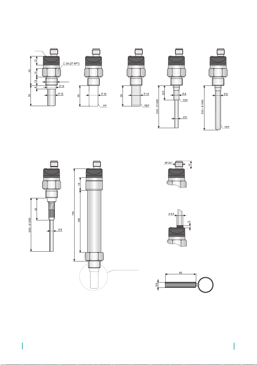
5 .
dimensions drawings
CLS 23_ 10 CLS 23_ 11
CLS 23_ 30
Variant A
with cable outlet
Variant C with connector
(except CLS–23N, NT, Xi, XiT)
Magnetic pen MP8
Electrode type according
to specic variants
CLS 23_ 12 CLS 23_ 21
High temperature variants
(CLS–23_T–10; 12; 20; 21; 30)
CLS 23_ 20
Thread
Types of threads:
G 3/8''
M18x1,5
M20x1,5
1/214 NPT
LED *
* Variant E without LED state indicator
Other manuals for CLS-23
2
Table of contents
Other Dinel Accessories manuals


