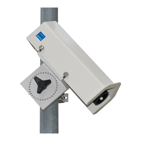
Lufft VS2k-UMB User manual


User Manual VS2k-UMB / VS20k-UMB V 2.3 / 28.01.2020
2 Inhaltsverzeichnis
Inhaltsverzeichnis
1Read before use............................................................................................................. 4
1.1 Safety instructions................................................................................................... 4
1.2 Designated use....................................................................................................... 4
1.3 Guarantee............................................................................................................... 4
1.4 Incorrect use ........................................................................................................... 4
2Scope of delivery............................................................................................................ 5
3Part numbers.................................................................................................................. 5
3.1 VS2k-UMB / VS20k-UMB........................................................................................ 5
3.2 Accessories............................................................................................................. 5
3.3 Spare parts ............................................................................................................. 5
3.4 Additional documents and software......................................................................... 5
4Equipment description.................................................................................................... 6
4.1 Operation mode ...................................................................................................... 6
5Installation...................................................................................................................... 7
6Connections................................................................................................................... 8
6.1 Screw-in connector.................................................................................................. 8
6.2 Power supply........................................................................................................... 8
6.3 RS485 interface ...................................................................................................... 8
6.4 Current output......................................................................................................... 8
7Commissioning............................................................................................................... 9
8Configuration.................................................................................................................. 9
8.1 Factory settings....................................................................................................... 9
8.2 Configuration with PC software UMB Config Tool ................................................... 9
8.3 Firmware update..................................................................................................... 9
9Calibration / Adjustment ................................................................................................10
9.1 Preconditions .........................................................................................................10
10 Communication..........................................................................................................10
10.1 Binary-Protocol.......................................................................................................10
10.1.1 Framing...........................................................................................................10
10.1.2 Addressing with class and device ID...............................................................11
10.1.3 Examples for the formation of addresses ........................................................11
10.1.4 Example of a binary protocol request..............................................................11
10.1.5 CRC Calculation..............................................................................................12
10.2 ASCII Protocol........................................................................................................12
10.2.1 Composition....................................................................................................12

User Manual VS2k-UMB / VS20k-UMB V 2.3 / 28.01.2020
3 Kap. 1 Read before use
10.2.2 Example of an ASCII request..........................................................................12
10.3 Channel assignment for data requests...................................................................13
10.4 Mapping standard ..................................................................................................14
11 Technical Data...........................................................................................................15
11.1 Visibility..................................................................................................................15
11.2 Storage conditions..................................................................................................15
11.3 Operating conditions ..............................................................................................15
11.4 Electrical Data........................................................................................................15
11.5 Interfaces...............................................................................................................15
11.6 Mechanical Data ....................................................................................................15
12 Possible failures.........................................................................................................16
13 Service and maintenance ..........................................................................................16
14 Disposal.....................................................................................................................17
15 Manufacturer .............................................................................................................17

User Manual VS2k-UMB / VS20k-UMB V 2.3 / 28.01.2020
Chapter 1 Read before use 4
1 Read before use
Before using the equipment, please read the operating manual carefully and follow the
instructions in every detail.Verwendete Symbole
Important information concerning potential hazard for the user
Important information concerning the correct operation oft he equipment
1.1 Safety instructions
•Installation and commissioning must only be carried out by suitably qualified
specialist personnel.
•Never take measurements on or touch live electrical parts.
•Pay attention to the technical data and storage and operating conditions
The visibility sensor VS2k emits invisible IR radiation and is classified into risk group 1
(low risk) according to IEC 62471:2006 “Photobiological safety of lamps and lamp
systems”. Please observe the following safety instructions:
•Do not look into the beam directly
•An exposure of more than 500s can lead to damage to the eye
•Avert your eyes for at least 60s after a long exposure to the beam
•Do not expose users of telescope optics
1.2 Designated use
•The equipment must only be operated within the range of the specified technical data.
•The equipment must only be used under the conditions and for the purposes for
which it was designed.
•The safety and operation of the equipment can no longer be guaranteed if it is
modified or adapted.
1.3 Guarantee
The guarantee period lasts 24 months from the date of delivery on. The guarantee is forfeited
if the designated use is violated.
1.4 Incorrect use
•If the equipment is installed incorrectly
- It may not function
- It may be permanently damaged
- It may fall down and hurt someone
•If the equipment is not connected correctly
- It may not function
- It may be permanently damaged
- You may risk an electric shock

User Manual VS2k-UMB / VS20k-UMB V 2.3 / 28.01.2020
5 Chapter 2 Scope of delivery
2 Scope of delivery
Visibility sensor
VS2k-UMB /
VS20k-UMB
Connection cable 10 m no ill.
3 Part numbers
3.1 VS2k-UMB / VS20k-UMB
8366.U70.....................Visibility sensor VS2k-UMB
8366.U90.....................Visibility sensor VS20k-UMB
3.2 Accessories
Interface converter ISOCON-UMB.....................................8160.UISO
Power supply 24V/4A........................................................8366.USV1
Surge protection................................................................8379.USP
Calibration kit ....................................................................8366.UKAL2
3.3 Spare parts
Connection cable 10 m......................................................8366.UKAB10
Connection cable 20 m......................................................8370.UKAB20
3.4 Additional documents and software
The following documents and software are available for download on www.lufft.com:
•Operating manual......... this document
•UMB protocol................Communication protocol for UMB devices
•Firmware.......................latest firmware for the equipment
•UMB Config Tool .......... PC configuration software for UMB sensors

User Manual VS2k-UMB / VS20k-UMB V 2.3 / 28.01.2020
6 Chapter 4 Equipment description
4 Equipment description
The VS2k-UMB / VS20k-UMB is a visibility measurement device for the determination of
optical visibility in the range of 0 –2000m / 0 –20000m (32 –6500 ft / 32 –65617 ft), as
needed e.g. in the realm of environmental data acquisition in traffic management equipment.
4.1 Operation mode
Visibility is determined by measuring reflectance in accordance with the 42° forward
scattering principle
1
.
The particles in the field of measurement (e.g. fog droplets) scatter the infrared light emitted
by the transmitter. The receiver measures the rate of scattered light from which the
reflectance is calculated. Visibility is then computed taking account of the set border contrast.
The measurements are polled via the RS485 interface or transmitted as an analogue signal
via the current output.
The device is connected by means of an 8-pole screw-in connector using the associated
connection cable.
Windows PC software is available for configuration and measurement polling during
commissioning.
1
In a horizontal plane

User Manual VS2k-UMB / VS20k-UMB V 2.3 / 28.01.2020
7 Chapter 5 Installation
5 Installation
The device is installed on a mast (diameter 40mm ... 80mm) using the mast fitting provided.
In order to have your instrument work properly and for a long time, adhere to the following
points:
-Installation height above ground min. 1.5 m (4.9 ft)
-Turn away the measurement aperture from the road
-Distance to the road > 2 m / 6,5 ft
-Do not mount any other devices within 50 cm (1.6 ft) above or below the VS2k-UMB /
VS20k-UMB
-Make sure that a distance of 2 m (6.5 ft) in front of the measurement aperture is free of
any kind of objects (masts, trees, grass, bushes etc.)
Installation sketch:
WARNING:
-Only approved and tested appliances (conductors, risers etc.) must be used to install the
device on the mast.
-All relevant regulations for working at this height must be observed.
-The mast must be sized and anchored appropriately.
-The mast must be earthed in accordance with the corresponding regulations.
-Safety regulations concerning work next to or on a traffic lane must be observed.
If the equipment is installed incorrectly
-it may not function
-It may be permanently damaged
-It may fall down and hurt someone

User Manual VS2k-UMB / VS20k-UMB V 2.3 / 28.01.2020
8 Chapter 6 Connections
6 Connections
6.1 Screw-in connector
There is an 8-pole screw-in connector on the underside of the device. It serves to connect
the power supply and the interfaces using the corresponding connection cable.
1....white.....negative power supply
2....brown ...positive power supply
3....green....RS485_A
4....yellow...RS485_B
5....grey......not assigned
6....pink.......not assigned
7....blue ......current output (-)
8....red........current output (+)
The cable marking is in accordance with DIN 47100
The screening of the connection cable must NOT be laid to earth in the control
cabinet!
If the equipment is not connected correctly
-It may not function
-It may be permanently damaged
-You may risk an electric shock
6.2 Power supply
The VS2k-UMB / VS20k-UMB is powered by 24VDC. The power supply unit must be
approved for operation with equipment of protection class III (SELV).
6.3 RS485 interface
The device has a DC-isolated half-duplex 2-wire RS485 interface with the following settings:
Data bits:............................8
Stop bit:..............................1
Parity:.................................none
Settable baud rates:...........1200, 2400, 4800, 9600, 14400, 19200*, 28800, 57600
* = factory setting and baud rate for firmware update
6.4 Current output
The current output is DC-isolated and can be configured as follows:
off...................the output transmits 0 mA
4 ... 20 mA* ....the output transmits the visibility in accordance with the configuration
20 ... 4 mA......inverts the visibility output
In case of a fault on the device the fault current indicated during configuration is transmitted.
The load resistance on the current output must be less than 300 Ohms.

User Manual VS2k-UMB / VS20k-UMB V 2.3 / 28.01.2020
9 Chapter 7 Commissioning
7 Commissioning
When the VS2k-UMB / VS20k-UMB is connected to the power supply a rattling sound must
be heard. It comes from the spider defender which is switched on together with the device in
the first place and again later sporadically in order to deter spiders from attaching their webs
to the sensor.
8 Configuration
Lufft provides a PC software for configuration purposes. It allows the user to set up the
device according to his necessities.
8.1 Factory settings
The VS2k-UMB / VS20k-UMB is supplied with the following settings:
Device ID:................................... 1
Baud rate:................................... 19200
RS485 protocol........................... UMB binary
Current output VS2k-UMB.......... 4 –20 mA corresponding to 0 –2000 m (linear)
Border contrast........................... 5 %
Averaging interval....................... 5 min
In case several VSx devices are operated in one UMB network, the ID must be changed
since each device requires a unique ID. It makes sense to use ascending IDs starting from 1.
8.2 Configuration with PC software UMB Config Tool
The basic functioning of the PC software UMB-ConfigTool.Net as well as all single steps for
the configuration are described in detail in the online help of the software.
8.3 Firmware update
The description of the firmware update can be found in the manual of the UMB-
ConfigTool.Net.

User Manual VS2k-UMB / VS20k-UMB V 2.3 / 28.01.2020
10 Chapter 9 Calibration / Adjustment
9 Calibration / Adjustment
The device has undergone a calibration in the factory when deliverd. The recommended
calibration interval is 12 months. An on-site calibration kit can be purchased.
9.1 Preconditions
•Visibility must be at least 2000m / 6562 ft
•No precipitation
•PC / Laptop with serial interface
•UMB-Config-Tool.Net (PC-Software)
•Calibration kit (Lufft ref.-no.: 8366.UKAL2)
The exact description of how to carry out the calibration can be found in the online help of the
software UMB-ConfigTool.Net
10 Communication
Depending on the configuration of the device, the visibility can be requested in binary or
ASCII-protocol.
10.1 Binary-Protocol
This operating manual will show you an example of an online data request. For more
information about the protocol please download the document ‘UMB Protocol’ on
www.lufft.de.
10.1.1 Framing
Der Daten-Frame ist wie folgt aufgebaut:
1
2
3 - 4
5 - 6
7
8
9
10
11 ... (8 + len)
optional
9 + len
10 + len
11 + len
12 + len
SOH
<ver>
<to>
<from>
<len>
STX
<cmd>
<verc>
<payload>
ETX
<cs>
EOT
SOH Control character for the start of a frame (01h) 1 byte
<ver> Header version number, e.g.: V 1.0 →<ver> = 10h = 16d; 1 byte
<to> Receiver address, 2 bytes
<from> Transmitter address, 2 bytes
<len> Number of data bytes between STX and ETX; 1 byte
STX Control character for the start of the payload data transmission (02h); 1 byte
<cmd> Command; 1 byte
<verc> Version number of the command; 1 byte
<payload> Data bytes; 0 –210 byte
ETX Control character for the end of the payload data transmission (03h); 1 byte
<cs> Check sum, 16 bit CRC; 2 byte
EOT Control character for the end of the frame (04h); 1 byte
Control characters: SOH (01h), STX (02h), ETX (03h), EOT (04h).

User Manual VS2k-UMB / VS20k-UMB V 2.3 / 28.01.2020
11 Chapter 10 Communication
10.1.2 Addressing with class and device ID
Addressing is done with a 16 bit address. It is divided inot a sensor class ID and a device ID
Adress (2 bytes = 16 bit)
Bit 15 –12 (upper 4 bits)
Bit 11 –8
Bit 7 –0 (lower 8 Bit)
Class ID (0 bis 15)
Reserve
Device ID (0 –4095)
0
Broadcast
0
Broadcast
3
Visibility (VS2k-UMB / VS20k-UMB)
1 - 4095
available
15
Master or control devices
For classes and deviced ID=0 is assigned to a broadcast. It is thus possible to send a
broadcast on a specific class. However, this will only make sense if there is only one single
device of the respective class on the bus.
10.1.3 Examples for the formation of addresses
Addressing e.g. a VS2k-UMB with the device ID (serial number) 0001 works as follows:
Class ID for visibility is 3d = 3h
Device ID (serial no.) is e.g. 001d = 001h
By compiling the class with the device ID the following address will result: 3001h (12289d).
10.1.4 Example of a binary protocol request
If for example a visibility sensor with the device ID (serial number) 0001 is to be polled from a
PC according to the current visibility (0 –2000m), this takes place as follows:
Sensor:
The class ID for the visibility sensor is 3 = 3h
The device ID (serial number) is 0001 = 0001h
Putting the class and device ID’s together gives a target address of 3001h.
PC:
The class ID for the PC (master unit) is 15 = Fh
PC-ID is for example 22 = 016h
Putting the class and PC ID’s together gives a sender address of F016h
The length <len> for the online data request command 4d = 04h,
The command for online data request is 23h,
and the version number of the command is 1.0 = 10h.
The channel number is shown under <payload>; as can be seen from the channel list, the
current visibility 0 –2000m in channel 601d = 259h
The calculated CRC is D40Dh
The request to the device:
SOH
<ver>
<to>
<from>
<len>
STX
<cmd>
<verc>
<channel>
ETX
<cs>
EOT
1
2
3
4
5
6
7
8
9
10
11
12
13
14
15
16
01h
10h
01h
30h
16h
F0h
04h
02h
23h
10h
59h
02h
03h
0Dh
D4h
04h

User Manual VS2k-UMB / VS20k-UMB V 2.3 / 28.01.2020
12 Chapter 10 Communication
The answer of the device:
SOH
<ver>
<to>
<from>
<len>
STX
<cmd>
<verc>
<status>
<channel>
<typ>
1
2
3
4
5
6
7
8
9
10
11
12
13
14
01h
10h
16h
F0h
01h
30h
0Ah
02h
23h
10h
00h
59h
02h
16h
<value>
ETX
<cs>
EOT
15
16
17
18
19
20
21
22
00h
00h
FAh
44h
03h
5Eh
11h
04h
<status> = Device o.k.
<typ> = Data type of the following value; 16h = Float (4 Byte, IEEE Format)
<value> = 44FA0000h corresponds to the float value 2000.00
The visibility is therefore 2000m.
The Checksumme (115Eh) will help to check if the data transmission was correct.
WARNING: Little endian (Intel, lowbyte first) applies when transmitting word and float
variables, of addresses or CRC for example. This means first the LowByte and then the
HighByte.
10.1.5 CRC Calculation
CRC is calculated according to the following rules:
Norm: CRC-CCITT
Polynomial: 1021h = x16 + x12 + x5+ 1 (LSB first mode)
Start value: FFFFh
(Warning! In contrast to earlier Lufft protocols, in this case the start value for CRC calculations is not 0h but
FFFFh according to CCITT!!)
Further information can be found in the description of a CRC in the UMB Protocol V1_0.
10.2 ASCII Protocol
The ASCII protocoll allows to communicate easily with the devices.
The ASCII protocol serves exclusively for online data requests and is not protected by a
CRC. The device does not respond to unintelligible ASCII commands!
10.2.1 Composition
An ASCII command is introduced with the character ‘&’ and ended with the character CR
(0Dh). There is an empty character (20h) between the individual blocks; displayed with an
underscore ‘_’. Characters which represent an ASCII value are in simple inverted commas.
10.2.2 Example of an ASCII request
If for example a visibility sensor with the device ID (serial number) 0001 is to be polled from a
PC according to the current visibility (0 –2000 m), this takes place as follows:
A measurement value from a specific channel is polled with the command “M”.
Request: ‘&’_<ID>5_‚M’_<channel>5CR

User Manual VS2k-UMB / VS20k-UMB V 2.3 / 28.01.2020
13 Chapter 10 Communication
Response: ‘$’_<ID>5_‚M’_<channel>5_<value>5CR
<ID>5Device address (5-point decimal with leading noughts)
<channel>5Indicates the channel number (5-point decimal with leading noughts)
<value>5Measurement value (5-point decimal with leading noughts); a value scaled to 0
–65520d. From 65521d –65535d various error codes are defined.
Example:
Request: &_12289_M_00601
With this request, channel 601 of the device with address 12289 (VS2k-UMB with the device
ID 0001) is polled.
Response: $_12289_M_00601_03456
With the scaling for visibility the following calculation then results:
0d corresponds to 0 metres
65520d corresponds to 32760 metres
03456d corresponds to 32760 / 65520 * 03456 = 1728 metres
10.3 Channel assignment for data requests
The following channel assignment is valid for online data request in binary protocol. In the
ASCII protocol all channels are transmitted in the mapping standard.
Channel
Data type
Measurement unit
Measurement rante
Description
Current
Average
Visibility
600
650
float
in metres
10 –1000 Meter
601
651
float
in metres
10 –2000 Meter
602
652
float
in kilometres
0.01 –1.000 km
603
653
float
in kilometres
0.01 –2.000 km
604
654
float
in feet
32 –3000 feet
605
655
float
in feet
32 –6500 feet
606
656
float
in miles
0.006 –0.600 miles
607
657
float
in miles
0.006 –1.200 miles
608
658
unsigned
short
in the mapping
standard
20 –4000
609
659
float
m
10 –20000
610
660
float
km
0.01 –20.00
611
661
float
ft
32 –65000 ft
612
662
float
miles
0.006 –12.400 miles
Ambient temperature
100
150
float
in °C
-40 - +80 °C
101
151
in °F
-40 - +176 °F
102
152
unsigned
short
in the mapping
standard
Service
4000
---
unsigned char
logical
0 - 100.255
Pollution degree sender
4001
---
unsigned char
logical
0 - 100.255
Pollution degree receiver

User Manual VS2k-UMB / VS20k-UMB V 2.3 / 28.01.2020
14 Chapter 10 Communication
4002
---
unsigned char
logical
0/1
Long time pollution recognition
value sender2
4003
---
unsigned char
logical
0/1
Long time polllution recognition
receiver
4030
unsigned char
logical
0 = OFF
1 = AUTO-Motor on
2 = AUTO-Motor off
Spider Defender Status
4040
---
unsigned long
in s
0…4294967295
Elapsed time since system start
4000
---
unsigned char
logical
0…100.255
TLS FG3
1060
3 Byte
TLS-Code FG3:
10 –1000 Meter
Byte 1: Typ der DE-
Daten (Typ 60)
10 = 10d = 000Ah
Byte 2: Messwert low
byte
1000 = 1000d = 03E8h
Byte 3: Messwert high
byte
The current value transmits the current measurement. For the average value, the
measurements are averaged over the configured time period.
10.4 Mapping standard
Mapping standard
Visibility value range
0 - 65520
0 –32760 m
0 –32,76 km
0 –107480,315 feet
0 –20,3561203 miles
Ambient temperature value range
-40 - +80 °C
-40 - +176 °F
Dirt recognition
0 –100 %
Spider Defender Status
0 –1 „0“, „1“, Error
2
Long time pollution is only measured in the darkness in order to exclude any influence of scattered light. Additionally the long
time pollution is verified at each start of the device in order to avoid unnecessary maintenance actions. For this reason the
corresponding channels cannot be read out during the first 15 minutes after the start of the device. (BUSY). This kind of
verification allows a quick maintenance without having to carry out manual changes in the configuration. The current pollution
degree can be read out at any time in the corresponding channels (4000 and 4002).

User Manual VS2k-UMB / VS20k-UMB V 2.3 / 28.01.2020
Chapter 11 Technical Data 15
11 Technical Data
11.1 Visibility
Measuring principle:....................... 42° forward scattering
3
Measurement:................................ Visibility
Measuring range VS2k-UMB:......... 10m - 2000 m; 32 - 6500 feet; 0.006 –1.200 miles
Measuring range VS20k-UMB:....... 10m - 20000 m; 32 - 65616 feet; 0.006 –12.00 miles
Accuracy: ....................................... +/- 10% visibility
11.2 Storage conditions
Permissible storage condition:........ -40°C ... +70°C (-40ºF…158ºF)
Permissible relative humidity:......... 0 ... 100% r.H. (non condensing)
....................................................... 0 … 98% (inside packaging)
11.3 Operating conditions
Permissible operating temperature:... -40°C ... +60°C (-40ºF….140ºF)
Permissible rel. humidity:................... 0 ... 100% r.H.
11.4 Electrical Data
Voltage supply:............................... 20 ... 30 VDC; typical 24 VDC
Current consumption:..................... < 200 mA (motor running and current outputs active)
about 100 mA in normal mode and RS485 output
Power consumption........................ 3 W (typical), 10 W (max.)
Protection class:............................. III (SELV)
11.5 Interfaces
RS485 (2-wire, half duplex) for configuration and measurement polling
Analogue output (4 –20mA) for measurement value output.
11.6 Mechanical Data
Dimensions (W x H x D):................ approx. 550 x 80 x 230 mm
Weight:........................................... approx. 4 kg without holder
....................................................... approx.. 5.6 kg with holder
Protection class:............................. IP66
3
In a horizontal plane

User Manual VS2k-UMB / VS20k-UMB V 2.3 / 28.01.2020
16 Chapter 12 Possible failures
12 Possible failures
Description
Reason / Steps to resolve
The instrument always measures the
maximum visibility
- Transport protection is still in place
→Remove protection caps
The device does not respond
- Check power supply
- Check interface connection
- wrong device ID →check ID
The device does not allow adjustment
- check if device is very dirty
„Calibration error 0“
during calibration with the UMB Config
Tool
Startup of the VS2k-UMB / VS20k-UMB not
finished. Waiting time between switching on /
resetting and start of the calibration must be at
least 90 s
13 Service and maintenance
In order to have the instrument work smoothly we suggest to regularly carry out the following
checks and maintenance jobs:
•Check if the optics is dirty and cleanse it if necessary using a lintless cloth, possibly
with alcohol or demineralised water
•Check cables and housing for damages and have them changed if necessary
•Recalibrate the sensor in the recommended interval. Make sure to take account of
the environmental preconditions for a recalibration.
During maintenance works, the instrument has to be disconnected from the power supply.
Service and maintenance jobs which require the instrument to be opened must only be
carried out by trained specialist personnel.

User Manual VS2k-UMB / VS20k-UMB V 2.3 / 28.01.2020
17 Chapter 14 Disposal
14 Disposal
The device must be disposed of in accordance with European Directives 2002/96/EC and
2003/108/EC (waste electrical and electronic equipment). Waste equipment must not be
disposed of as household waste! For environmentally sound recycling and the disposal of
your waste equipment please contact a certified electronic waste disposal company.
15 Manufacturer
For warranty or repair requests contact your local dealer or:
G. Lufft Mess- und Regeltechnik GmbH
Gutenbergstraße 20
D-70736 Fellbach
Postfach 4252
D-70719 Fellbach
Tel: +49(0)711-51822-0
Fax: +49(0)711-51822-41
Mail: i[email protected]
www.lufft.de

This manual suits for next models
1
Table of contents
Other Lufft Accessories manuals

Lufft
Lufft WS Series User manual

Lufft
Lufft IRS31Pro-UMB User manual

Lufft
Lufft 8810.U051 User manual

Lufft
Lufft MARWIS User manual

Lufft
Lufft ARS31Pro-UMB User manual

Lufft
Lufft ARS31-UMB User manual

Lufft
Lufft CHM 15k Nimbus User manual

Lufft
Lufft SHM 31 User manual

Lufft
Lufft WS800-UBM User manual

Lufft
Lufft VENTUS-UMB User manual
Popular Accessories manuals by other brands

DH Instruments
DH Instruments RUBBER SHOE ACCESSORY - SCHEMA P-N 400202 manual

SICK
SICK WI130 quick start guide

Panasonic
Panasonic LNJ115W8PRA Specification sheet

Conveyor Components Company
Conveyor Components Company RMS-8S installation instructions

SMC Networks
SMC Networks IZD10-*10 Series Operation manual

Kodak
Kodak PPS600 user manual