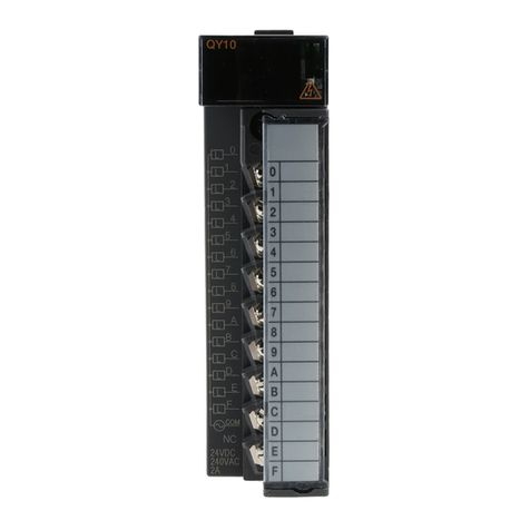
Sensor Access IC500 User manual

IC500 / IC500IP
Quick Start Guide

As with all Sensor controllers, the IC500 and the IC500IP are based on microprocessors which are designed to
operate 2 hours a day. Like all our controllers, the IC500 range can be connected to various external ele-
ments such as card readers, electric locks, alarm detection devices, printers, computers, etc., but the installer
should be aware that this kind of system can be subjected to the following problems:
1- Electro Magnetic Interference (EMI). EMI can be present along the cables that
connect the controller to the external elements. Undesired voltage may result in
erratic behaviour, random power ups, or even in serious damage.
2- The Exterior Elements themselves. In cases where readers, door locks, alarms,
etc., have not been supplied/recommended by Sensor, erratic behaviour or com-
plete failure can sometimes result.
It is absolutely imperative that from the moment a Sensor controller is installed the individual responsible
for the installation adheres to the directives listed below. Should any of these directives not be adhered
to Sensor cannot assume responsibility for any problems that might be encountered.
1. The control unit must never be installed inside a high voltage electrical power box nor must it be placed in
close proximity to large transformers and/or high voltage/current source devices. Since the controller may
require maintenance it is also important to consider the accessibility of the unit.
2. The IC500 boards must be separately grounded so it is important to ascertain whether the installation site
can provide adequate grounding facilities.
3. It is essential to plug the mains power cable into a clean line (i.e. a line not being used by other pieces of
equipment) or into an independent line which has been specifically allocated to the controller.
. The cover or case that contains the controller should be tightly screwed down or locked in place.
5. Never use the system cables guide to pass wires from another system such as using a conduit also used by
other cables.
IN RODUC ION
2
IC500-E2/IC500IP-E2 BASIC SPECIFICA ION
Cardholders Up to 8700 Events Up to 2800
Doors 1 Door Com Bus 1
Readers 2 Readers TCP-IP On Board (option)
Inputs Power Supply E2, 2 amp PSU
Outputs 3 Relay Outputs (12VDC @ 2 amp)

The board is powered by a 12vDC current. With no external devices (readers, locks, alarms, etc.) attached,
the board’s consumption is 120mA maximum (IC500) or 370mA maximum (IC500IP). The maximum con-
sumption allowed through the 5V terminals on terminal blocks J1 and J2 is 150 ma.
When supplied in Sensor’s Power Supply Unit (E2) you are given independent outputs:
POWER SOURCES AND BOARD CONSUMP ION
- 2 x 12V/250ma terminals - for powering the card/fob readers
- 1 x 12V/1A terminals - for powering the electric door locks
- 1 x 12V/500ma terminal - for powering the controller
See the E-Series Instruction Sheet for further details on the PSU cabinet:
http://public.sensoraccess.co.uk/GuardPointPro/Manuals/hardware/E-SeriesInstructionSheet.pdf
CONNEC ING HE READERS
The IC500 controllers can recognise almost any kind of reader technology the use of switches 6, 7 and 8 on
the dipswitch bank DS1. However for the vast majority of installations dipswitch 6 should be set to ON and
switches 7 & 8 set to OFF (Wiegand with parity check). Each reader comes complete with a length of cable
attached. However, there may be times when you want to extend this cable further. In these situations it is
important to select the correct type.
Sensor recommend Belden 9 21 for Proximity/Keypad readers and Belden 8 58 for Biometric
readers
CONNEC ING AN INPU
A magnetic contact, passive infra-red unit, request to exit switch or any other form of contact can be con-
nected to and monitored via the IC500. As standard, input I3 is configured to allow connection of Request to
Exit (REX) and I1 configured for the connection of a Door monitoring contact.
Sensor recommend any 22AWG, 2 conductor cable
3


:::
CONNEC ING O HE PC (IC500 Serial Port)
The IC500 controller Communicate to the PC via a Serial port The serial port on the controller can be config-
ured to use either the RS232 or RS 85 protocols. If the controller has to be connected to a PC at less than 30
meters either the RS232 port or the RS 85 port may be used. If the distance is greater than 30 meters or if
several controllers must be connected together the RS 85 port should be used.
RS232 Port. Jumpers JP2
6
CONNEC ING HE LOCK
The Door Output on the controller can support a maximum of 2 V/1A. - If the release mechanism has a
charge that exceeds this limit or has a strong inductive charge (as in the case, for example, of revolving doors
or turnstiles) then it will be necessary to use an intermediate relay between the controller and the Door.
Sensor recommend any 18AWG, 2 conductor cable
The three signals - 0v, Rx and Tx - are connected to a serial plug in the PC as follows:
25 Pin Plug (PC) 9 Pin Plug (PC) IC1000+ J3
Pin 7 (0v) Pin 5 (0v) 0v
Pin 2 (Transmit) Pin 3 (Transmit) Rx/L
Pin 3 (Receive) Pin 2 (Receive) Tx/H
In nearly all cases RS 85 connection will take place via an RS 85/USB interface, however in the
rare situations where an RS 85/RS232 interface is to be used, the interface should be wired to
the PC according to the details above.
To connect via an RS 85/USB interface, simply plug the USB connector into a port, and wire as
follows:
USB 85 IC500-E2
X- Rx/L
X+ Tx/H
RS485 Port. Jumpers JP2

he GuardPoint Pro / GuardPoint Pro Lite software can then be configured to communicate with the con-
troller via the RS485/USB interface. Fuller details and instructions on this connection can be found on the
datasheet supplied with the interface, or from the Sensor website.
The communication line is particular particularly susceptible to RFI interference. To prevent this, the follow-
ing rules should be considered:
7
Use a Belden 8 3 triple-wire cable ("Receive"/"Transmit"/0v) for the RS232 connection, and a
Belden 98 1 twisted and shielded pair cable for the RS 85 connection.
A good quality cable shield must be used and the shield must be connected to a strong earth.
The shield should be copper rather than aluminium, since the latter provides only partial attenua-
tion.
All communication cable shielding should be connected to only one extremity in order to avoid
the problem of ground loops, whereas the connection for the RS 85 wire shield should be carried
out at the level of the concentrator, and the connection for the RS232 wire shield should be car-
ried out at the level of the terminal.
A distance of at least 50cm must separate all connecting cables from high-tension cables, from
cables connected to an electrical power box controlled by the system, or from any cables capable
of generating strong interference (such as cables connected to high-power motors, generators,
wireless telephone, etc.). Since it is often located besides a variety of cables, the external tele-
phone line can also be a source of strong interference.
Extremely high tension produced by lightning bolts can enter the terminals through these lines.
Such tension can reach the level of hundreds of thousands of volts, so it is advisable to use some
form of surge protection.
Important!
- Do not connect the communication cable screen at any point other than at the RS232/RS 85 inter-
face end.
- For all TCP/IP connections, Belden 162 P (2 AWG, CAT5, shielded Ethernet) cable is recommended.
- For all RS232 connections, Belden 8 3 (22AWG, non-twisted) cable is recommended.
- For all RS 85 connections, Belden 98 1 (2 AWG, twisted and shielded pair) cable is recommended.

8
CONNEC ING HE IC500IP ( CP/IP Port)
The IC500IP controller is supplied with a TCP/IP socket on board, allowing it to be assigned an IP address and
so added to a TCP/IP network. In order to connect the IC500 plug one end of a standard RJ 5 network cable
into the socket, and the other either into your router/hub or directly into the Ethernet socket on a PC; the
controller will then appear on the network. Before it can be used the controller must be configured via the
application DS Manager (available on the GuardPoint Pro disc, or for free download from the Sensor web-
To configure the controller, please go to Start,
Programs, Tibbo, DS Manager. A window
such as that on the right will now appear.
In the main panel of the window will be a list
of all currently detected TCP/IP controllers.
It is almost certainly the case that your IC500
is new and so has a default IP address. This
along with some other settings will need to be
changed.
Click on the visible TCP/IP controller to select
it then click on the Settings button at the top
of the window to bring up the configuration
window.
There are a series of tabs running across the top of the window. Using the tabs you will need to locate the
following settings and change them:
IP-address This should be a unique address
Port This should be set to ‘1001’
Transport Protocol This should be set to ‘1-TCP’
RTS/CTS flow control This should be ‘0-Disabled or remote’
DTR mode This should be ‘0-Idle or remote’
Baud rate This should be set to ‘3-9600 bps’
Once changed, click Ok to return to the main window. The IC500 is now configured and its status icon – rep-
resented by the blue plug to the left - should be solid and clear (as in the screenshot).
The controller is now ready to communicate with the software. For full details on establishing communica-
tion, please refer to the GuardPoint Pro / Pro Lite manual.
This manual suits for next models
3
Table of contents
Other Sensor Access Controllers manuals
