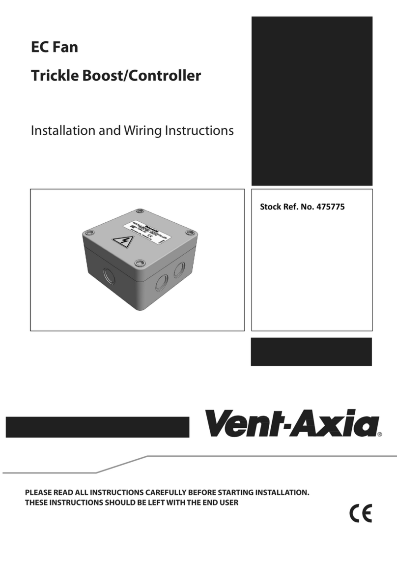
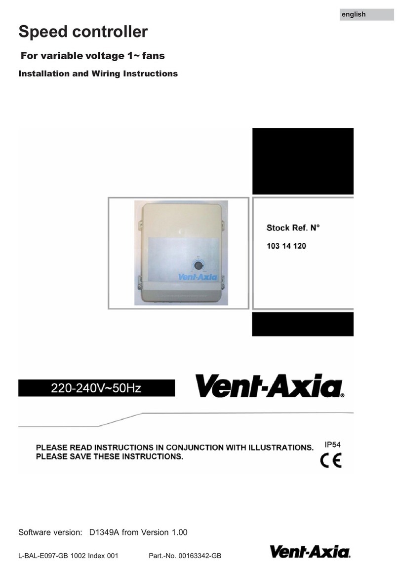
Vent-Axia SC5001 User manual

Electronic Speed
Controller Range
StockRef.N°
SC5001
SC5030

T
able
o
f
contents
S
A
F
E
T
Y AND
P
R
E
C
A
U
T
I
O
N
S
3
P
R
OD
U
C
T
D
ES
C
R
I
PT
ION
4
STOCK REF NUMBERS
4
INTENDED
AREA
OF USE
4
TECHNICAL
DA
T
A
4
S
T
ANDARDS
4
OPERATIONAL DIAGRAMS
5
WIRING AND
C
O
NNE
C
T
I
O
N
S
5
MOUNTING
I
N
S
T
R
U
C
TI
O
N
S
IN STEPS
5
OPERATING
I
N
S
T
R
U
C
T
I
O
N
S
8
TRANSPORT AND STOR
A
G
E
8
W
A
RR
A
N
T
Y AND RESTRICTIONS
8
M
A
I
NTE
N
A
N
C
E
8
2-
8

S
A
F
E
T
Y AND PRECAUTIONS
R
ead all
t
he
in
f
or
m
a
t
i
on
,
t
he
d
a
t
as
he
e
t
,
m
o
un
t
ing
and
op
er
a
t
ing in
s
t
r
uc
t
i
on
s
and
s
t
u
d
y
t
he wiring and
c
onn
e
c
t
i
on
diagram
b
e
f
or
e
working
w
i
t
h
t
he
pro
duc
t
.
F
or
personal and
e
qu
ipm
en
t
sa
f
e
t
y
,
and
for
op
t
imum
pro
duc
t
p
er
f
or
m
an
c
e,
make sure
you
en
t
ir
ely
under
s
t
and
t
he
c
on
t
en
t
s
b
e
f
or
e
in
s
t
a
ll
ing,
using, or
m
a
in
t
a
ining
t
h
i
s
pro
duc
t
.
F
o
r
sa
f
e
t
y
reasons,
un
a
u
t
h
o
r
i
s
e
d
conversion and
/
or
m
o
d
i
f
i
c
a
t
i
o
n
s
of
t
he
pro
duc
t
are
in
a
dmi
ss
ib
l
e.
The
p
r
o
d
u
c
t
should
n
o
t
be exposed
to
abnormal
c
o
n
d
i
t
i
o
n
s
,
such as:
e
x
t
r
e
m
e
te
m
pe
r
a
t
ur
e
s
,
d
i
r
e
c
t
s
un
l
i
g
h
t
or
v
i
b
r
a
t
i
o
n
s
.
Long-term exposure
to
chemical vapours in
high
c
o
n
c
e
n
t
r
a
t
i
o
n
can
a
ff
e
c
t
t
h
e
p
r
o
d
u
c
t
p
e
r
f
o
r
m
a
n
c
e.
Make sure
t
h
e
work en
v
ir
onm
en
t
is
as dry as possible; avoid
c
onden
sa
t
i
on
.
All
i
n
s
t
a
ll
a
t
i
o
n
s
shall comply
w
i
t
h
local
h
e
a
l
t
h
and
sa
f
e
t
y
r
e
g
u
l
a
t
i
o
n
s
and
l
o
c
a
l
el
e
c
t
r
i
c
a
l
s
t
and
ar
d
s
and approved codes. This
pro
duc
t
can only be
in
s
t
a
ll
e
d
b
y
an
engineer or a
t
e
c
hn
i
c
i
an who has
e
xp
er
t
knowledge
of
t
he
pro
duc
t
and
sa
f
e
t
y
p
r
e
c
au
t
io
n
s
.
Avoid
c
o
n
t
a
c
t
s
w
i
t
h
energised
e
l
e
c
t
r
i
c
a
l
p
a
r
t
s
.
Always
d
i
s
c
o
nn
e
c
t t
h
e
p
o
w
e
r
supply
b
e
f
or
e
c
onn
e
c
t
ing,
servicing or repairing
t
he
pro
duc
t
.
Always
verify
t
h
a
t
you apply
a
pp
r
o
p
r
i
a
t
e
power supply
to
t
h
e
p
r
o
d
u
c
t
and use
a
pp
r
o
p
r
i
a
t
e
wire size and
c
h
a
r
a
c
t
e
r
i
s
t
i
c
s
.
Make sure
t
h
a
t
all
t
h
e
screws and
nu
t
s
are well
t
i
g
h
t
e
n
e
d
and
f
u
s
e
s
(
i
f
any)
are
fi
tt
e
d
w
e
ll
.
Recycling
of
e
qu
ipm
en
t
and packaging should be
t
aken
in
t
o
c
on
s
i
der
a
t
i
on
and
t
he
s
e
should be disposed
of
in
accordance
w
i
t
h
local and
n
a
t
i
o
n
a
l
l
e
g
i
s
l
a
t
i
o
n
/
r
e
g
u
l
a
t
i
o
n
s
.
In case
t
h
e
r
e
are any
q
u
e
s
t
i
o
n
s
t
h
a
t
are
n
o
t
answered, please
c
o
n
t
a
c
t
y
o
u
r
technical
s
up
po
r
t
or
c
o
n
s
u
l
t
a
p
r
o
f
e
ss
i
o
n
a
l
.
3-
8

P
R
OD
U
C
T
D
ES
C
R
I
PT
ION
These
i
n
f
i
n
i
t
e
l
y
variable
fan
speed
c
o
n
t
r
o
ll
e
r
s
allow you
to
manually
a
d
j
u
s
t t
h
e
r
o
t
a
t
i
o
n
a
l
speed
of
single phase
AC
m
o
t
o
r
s
by varying
t
h
e
m
o
t
o
r
v
o
l
t
a
g
e
t
h
r
o
u
g
h
phase angle
c
o
n
t
r
o
l
.
The
i
n
t
e
g
r
a
t
e
d
AC
s
w
i
t
c
h
enables or disables
t
h
e
m
o
t
o
r
.
STOCK REF NUMBERS
INTENDED
AREA
OF USE
■Manual
c
o
n
t
r
o
l
of
t
h
e
m
o
t
o
r
/
fan
speed in
HVAC
a
pp
l
i
c
a
t
i
o
n
s
■For indoor use
o
n
l
y
TECHNICAL
DA
T
A
■Supply
v
o
l
t
a
g
e:
230
VAC
/
50—60 Hz
■
R
e
gula
t
e
d
o
u
t
p
u
t
to
m
o
t
or
:
Umin—Us
■
Un
r
e
g
u
l
a
t
e
d
o
u
t
p
u
t
:
230
VAC
/
max. 2
A
■Minimum speed
a
d
j
u
s
t
m
en
t
by
t
r
im
m
er
:
80—180
V
A
C
■Speed
c
o
n
t
r
o
l
:
►
from
low
to
h
i
g
h
■Enclosure:
►
E
x
t
e
r
n
a
l
:
ASA,
w
h
i
t
e
colour
(
28049
P
),
IP54
(according
to
EN
60529
)
►
I
n
t
e
r
n
a
l
:
polyamide,
n
a
t
u
r
a
l
colour, IP44
(according
to
EN
60529
)
■
O
p
er
a
t
ing
am
b
i
en
t
c
ond
i
t
i
on
s
:
►
te
m
pe
r
a
t
ur
e:
0—40
°
C
►rel.
h
umid
i
t
y
:
5—95 % rH
(
non
-
c
onden
s
ing
)
S
T
ANDARDS
■Low
V
o
l
t
a
g
e
D
i
r
e
c
t
i
v
e
2014
/
35
/
E
U
►EN
60529:1991
Degrees
of
p
r
o
t
e
c
t
i
o
n
provided by enclosures
(IP
C
o
d
e
)
A
m
e
n
dm
e
n
t
A
C
:
1993
to
EN
60529
►EN
60730
-
1
:
2011
A
u
t
o
m
a
t
i
c
e
l
e
c
t
r
i
c
a
l
c
o
n
t
r
o
l
s
for
household and simila
r
use -
P
ar
t
1: General
r
e
qu
ir
em
en
t
s
■
EMC
d
i
r
e
c
t
i
v
e
2014
/
30
/
E
U
:
►EN
60730
-
1
:
2011
A
u
t
o
m
a
t
i
c
e
l
e
c
t
r
i
c
a
l
c
o
n
t
r
o
l
s
for
household and simila
r
use -
P
ar
t
1: General
r
e
qu
ir
em
en
t
s
EN
61000
-
6
-
1
:
2007
E
l
e
c
t
r
o
m
a
g
n
e
t
i
c
c
o
mp
a
t
i
b
i
l
i
t
y
(
E
M
C
)
-
Pa
r
t
6-1:
Generic
s
t
and
ar
d
s
-
Im
mun
i
t
y
for
r
e
s
i
den
t
i
a
l
,
commercial and
l
i
g
h
t
indu
s
t
r
i
a
l
en
v
ir
onm
en
t
s
EN
61000
-
6
-
3
:
2007
E
l
e
c
t
r
o
m
a
g
n
e
t
i
c
c
o
mp
a
t
i
b
i
l
i
t
y
(
E
M
C
)
-
Pa
r
t
6-3:
Generic
s
t
and
ar
d
s
- Emission
s
t
and
ar
d
for
r
e
s
i
den
t
i
a
l
,
commercial and
l
i
g
h
t
-
indu
s
t
r
i
a
l
en
v
ir
onm
en
t
s
A
m
endm
en
t
s
A1:2011 and
A
C
:
2012
to
EN
61000
-
6
-
3
►
►
4-
8
■
WEEE
D
i
r
e
c
t
i
v
e
2012
/
19
/
E
U
■RoHs
D
i
r
e
c
t
i
v
e
2011
/
65
/
E
C
Stock Ref Nos Current Range (A)
SC5001 1-1,5
SC5030 0,2-3
Outputregulationfromlowtohigh

OPER
A
TIONAL DIAGRAM
WIRING AND
C
O
NN
EC
T
I
O
N
S
Spring
c
o
n
t
a
c
t t
e
r
m
i
n
a
l
block, cable cross
s
e
c
t
i
o
n
:
1,5 mm ;
p
i
t
c
h
MOUNTING INSTRUCTIONS IN STEPS
Before you start mounting the unit, read carefully “Safety and Precautions”
and
follow the
steps:
Flush m
oun
t
in
g
1
.
2
.
3
.
4
.
5.
D
i
s
c
o
nn
e
c
t t
h
e
mains
s
u
pp
l
y
.
Remove
t
h
e
knob by pulling
it
o
u
t
.
Unscrew
t
h
e
washer
to
remove
t
h
e
cover
of
t
h
e
e
x
t
e
r
n
a
l
e
n
c
l
o
s
u
r
e.
Do
t
he wiring according
to
t
he wiring diagram
(see
Fig. 1 Wiring and
c
onn
ec
t
i
o
n
s
).
Mount the internal enclosure into the wall according to the mounting
dimensions
shown in Fig. 2 Mounting dimensions - flush
mounting.
5-
8
U
m
i
n
r
a
nge
L
L1
Power supply, line
(
230
VAC
±10 %
/
50—60 H
z
)
Un
r
e
g
u
l
a
t
e
d
o
u
t
p
u
t
,
line
(
230
VAC
±10 %
/
50—60 Hz, Imax 2
A
)
N
Power supply,
n
e
u
t
r
al
N
Un
r
e
g
u
l
a
t
e
d
ou
t
pu
t
,
n
e
u
t
r
al
U2
R
e
g
u
l
a
t
e
d
o
u
t
p
u
t
to
m
o
t
o
r
,
n
e
u
t
r
a
l
U1
C
o
nne
c
t
i
on
s
R
e
g
u
l
a
t
e
d
o
u
t
p
u
t
to
m
o
t
o
r
,
l
i
n
e
2
5
mm
From low
to
high speed
U
o
u
t
[
%
]
Us
70
%
20
%
Min
Potentiometer
po
s
i
t
i
on
M
a
x
Of
f
O
n
S
w
it
ch
0

230
VAC
/
50—60 HZ
mo
t
o
r
6
.
A
d
j
u
s
t t
he Vmin
t
r
im
m
er
in orde
r
to
s
e
t t
he minimum speed.
The
f
a
c
t
or
y
s
e
tt
ing
is 100
V
A
C
.
M
o
un
t
back
t
h
e
cover and secure
it
w
i
t
h
t
h
e
w
as
h
e
r
.
P
u
t
back
t
h
e
knob and
t
u
r
n
it to
off
p
o
s
i
t
i
o
n
.
Turn on
t
h
e
power
s
up
p
l
y
.
7.
8
.
9.
6-
8
62
62
M
o
un
t
t
h
e
un
i
t
so
that
t
h
e
t
e
r
m
i
n
a
l
block and
c
o
nn
e
c
t
i
o
n
s
are
at
t
h
e
lower
s
i
d
e.
Fig. 2 Mounting
dimensions
-
flush
mounting
Correct
Incorrect
62
60
62
60
Fig.1 Wiring and Connections
PowerSupplyRegulatedoutput
230VAC/50‐60Hztomotor
Unregulated
o
u
t
p
u
t
:
230
VAC
±10 %
/
50—60 Hz,
Minimum speed
Adjustment trimmer
(factory pre set to
100 VAC)
Note

Surface m
oun
t
in
g
1
.
2
.
3
.
4
.
D
i
s
c
o
nn
e
c
t t
h
e
mains
s
u
pp
l
y
.
Remove
t
h
e
knob by pulling
it
o
u
t
.
Unscrew
t
h
e
washer
to
remove
t
h
e
cover
of
t
h
e
e
x
t
e
r
n
a
l
e
n
c
l
o
s
u
r
e.
M
o
un
t
t
h
e
e
x
t
e
r
n
a
l
enclosure
o
n
t
o
t
h
e
s
u
r
f
a
c
e
by means
of
t
h
e
screws and
d
o
w
e
l
s
adhering
to
t
he
m
o
un
t
ing
dimensions shown in Fig. 3
M
o
un
t
i
n
g
dimensions
-
surface
m
o
un
t
in
g
.
5
.
6
.
I
n
s
er
t
t
he cables
t
h
r
o
u
g
h
t
he
gr
omm
e
t
s.
Do
t
he wiring according
to
t
he wiring diagram
(see
Fig. 1 Wiring and
c
onn
ec
t
i
on
s
).
7.
I
n
s
er
t
t
he
in
t
ern
a
l
enclosure
in
t
o
t
he
e
x
t
ern
a
l
one and fix
it
using
t
he
s
c
r
e
w
s.
8
.
A
d
j
u
s
t t
he Vmin
t
r
im
m
er
in orde
r
to
s
e
t t
he minimum speed.
The
f
a
c
t
or
y
s
e
tt
ing
is 100
V
A
C
.
M
o
un
t
back
t
h
e
cover and secure
it
w
i
t
h
t
h
e
w
as
h
e
r
.
9.
10
.
P
u
t
back
t
h
e
knob and
t
u
r
n
it to
off
p
o
s
i
t
i
o
n
.
11. Turn on
t
h
e
power
s
up
p
l
y
.
7-
8
87
64
M
o
un
t
t
h
e
un
i
t
so
that
t
h
e
t
e
r
m
i
n
a
l
block and
c
o
nn
e
c
t
i
o
n
s
are
at
t
h
e
lower
s
i
d
e.
Fig. 3 Mounting
dimensions
-
surface
mounting
82
63,5
64
Correct
Incorrect
82
Note

OPER
A
TING
IN
S
T
RU
C
T
I
O
N
S
The
c
o
n
t
r
o
ll
e
r
is
to
be used only
w
i
t
h v
o
l
t
a
g
e
c
o
n
t
r
o
ll
a
b
l
e
f
a
n
s
/
m
o
t
o
r
s
.
Y
ou can
c
o
nn
e
c
t
several
m
o
t
o
r
s
to
t
h
e
c
o
n
t
r
o
ll
e
r
as long as
t
h
e
c
u
rr
e
n
t
l
i
m
i
t
is
n
o
t
exceeded.
The
m
o
t
o
r
should be
p
r
o
t
e
c
t
e
d
a
g
a
i
n
s
t
o
v
e
r
h
e
a
t
i
n
g
.
The minimum speed
t
r
i
mm
e
r
should be
a
d
j
u
s
t
e
d
so
t
h
a
t
t
h
e
m
o
t
o
r
c
a
nn
o
t
s
t
a
ll
a
t
minimum speed.
The
c
on
t
r
o
ll
er
r
e
s
t
ar
t
s
a
f
t
er
power
f
a
i
l
u
r
e.
In
case
of faulty
operation
Please check
i
f
:
■
t
h
e
r
i
g
h
t
v
o
l
t
a
g
e
is
a
pp
l
i
e
d
■
all
c
o
nn
e
c
t
i
o
n
s
are
c
o
rr
e
c
t
■
t
he machine
to
be
r
e
gula
t
e
d
is
f
un
c
t
i
oning
TRANSPORT AND STORAG
E
Avoid shocks and
e
x
t
r
em
e
c
ondi
t
i
on
s
;
s
t
o
c
k
in original
p
a
c
king
.
W
A
RR
A
N
T
Y AND RESTRICTIONS
Two years
f
rom
t
h
e
delivery
d
a
t
e
a
g
a
i
n
s
t
d
e
f
e
c
t
s
in
m
a
nu
f
a
c
t
u
r
i
n
g
.
Any
m
o
d
i
f
i
c
a
t
i
o
n
s
or
a
l
t
e
r
a
t
i
o
n
s
to
t
h
e
p
r
o
d
u
c
t
a
f
t
e
r
t
h
e
d
a
t
e
of
p
u
b
l
i
c
a
t
i
o
n
relieve
t
h
e
m
a
nu
f
a
c
t
u
r
e
r
of
any
r
e
s
p
on
s
ib
i
l
i
t
i
es.
The
m
an
u
f
a
c
t
u
r
er
bears no
r
e
s
p
on
s
ib
i
l
i
t
y
for
any
mi
s
pr
in
t
s
or
m
i
s
t
a
k
e
s
in
t
h
i
s
d
a
t
a
.
M
A
I
NTE
N
A
N
C
E
In normal
c
o
n
d
i
t
i
o
n
s
t
h
i
s
p
r
o
d
u
c
t
is
m
a
i
n
t
e
n
a
n
c
e
-
f
r
ee.
I
f
soiled, clean
w
i
t
h
adry
o
r
damp
c
l
o
t
h
.
In case
of
heavy
p
o
ll
u
t
i
o
n
,
clean
w
i
t
h
a non-aggressive
p
r
o
d
u
c
t
.
In
t
h
e
s
e
c
i
r
c
u
m
s
t
a
n
c
e
s
t
h
e
un
i
t
should be
d
i
s
c
o
nn
e
c
t
e
d
from
t
h
e
supply.
Pay
a
tt
e
n
t
i
o
n
t
h
a
t
no fluids
e
n
t
e
r
t
h
e
un
i
t
.
Only
r
e
c
o
nn
e
c
t
it to
t
h
e
supply
when
it
is
c
o
mp
l
e
t
e
l
y
d
r
y
.
8-
8
Use only
t
oo
l
s
and
e
q
u
i
pm
e
n
t
w
i
t
h
n
o
n
-
c
o
n
d
u
c
t
i
n
g
handles when working
o
n
electrical devices.
HeadOffice:FlemingWay,Crawley,WestSussex,RH109YX.Tel:01293526062Fax:01293551188
EUAuthorisedRepresentative:Vent‐AxiaBedrijvenweg177442CXNijverdalNederlandauthorisedrep@vent‐axia.nl
UKNATIONALCALLCENTRE,NewtonRoad,Crawley,WestSussex,RH109JA
SALESENQUIRIES:Tel:03448560590 Fax:01293565169
TECHNICALSUPPORT:Tel:03448560594 Fax:01293539209
Web:‐www.vent‐axia.com Email:‐info@vent‐axia.com
AspartofthepolicyofcontinuousproductimprovementVent‐Axiareservestherighttoalterspecificationswithoutnotice.
498068A1121
This manual suits for next models
1
Table of contents
Other Vent-Axia Controllers manuals

Vent-Axia
Vent-Axia 103 14 120 Assembly instructions

Vent-Axia
Vent-Axia SAC3 Assembly instructions

Vent-Axia
Vent-Axia 475775 Assembly instructions

Vent-Axia
Vent-Axia SAC 5 Assembly instructions

Vent-Axia
Vent-Axia LoWatt T Series User manual

Vent-Axia
Vent-Axia 563531A User manual

Vent-Axia
Vent-Axia ECOTRONIC SELV24 User manual

Vent-Axia
Vent-Axia Visionex User manual
Popular Controllers manuals by other brands

Evco
Evco Vcolor 348 Series Installer manual

Omnisense Systems
Omnisense Systems Joystick Controller quick start guide

Nibe
Nibe EME 20 Installer manual

Ametek
Ametek SurgeX SX2200 Series installation instructions

cashco
cashco HP Installation, operation & maintenance manual

Omron
Omron Z500 Series Setup manual