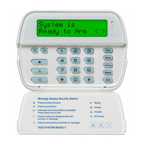
Sensor ALARM KEYPAD User manual

SENSOR ALARM KEYPAD
INSTALLATION AND USER MANUAL
MNMSC0107_ALARMKEYPAD January, 2007

MNMSC0107_ALARMKEYPAD: Alarm Keypad Installation and User Manual 2/11
TABLE OF CONTENTS
1. INTRODUCTION.......................................................................................................................... 3
2. REQUIREMENTS......................................................................................................................... 3
2.1 CHECKING FIRMWARE................................................................................................................. 3
3. SETTING UP THE SYSTEM....................................................................................................... 4
3.1 INSTALLING THE RCB ................................................................................................................. 4
3.2 WIRING THE ALARM KEYPAD ..................................................................................................... 4
3.3 SOFTWARE SETUP -INITIAL......................................................................................................... 5
3.4 SOFTWARE SETUP -GUARDPOINT PRO........................................................................................ 6
4. USING THE SYSTEM................................................................................................................... 7
4.1 ARMING ....................................................................................................................................... 7
4.2 DISARMING.................................................................................................................................. 8
4.3 STATUS ........................................................................................................................................ 8
5. ALARM ZONES............................................................................................................................. 9
5.1 LINKING ZONES ........................................................................................................................... 9
5.2 MULTIPLE ZONES ........................................................................................................................ 9
5.3 SHARED INPUTS......................................................................................................................... 10
APPENDIX A : TECHNICAL SUPPORT................................................................................... 11

1. INTRODUCTION.
The Alarm Keypad is a powerful product which, when connected to an IC2000 or IC4000 controller, will
allow a user to arm/disarm alarms in either a single zone or in multiple zones by activating and deactivating
inputs on the controller.
When combined with the GuardPoint Pro software, it can be configured to respond only to an authorised
user, to lock off doors, or to set multiple alarms. The status of any alarm type (whether it is armed or
disarmed) can also be queried.
2. REQUIREMENTS.
In order to establish a basic Alarm Keypad system, you will require the following:
An IC2000 or IC4000 Controller with latest firmware (see section 2.1)
A Redundant Communications Bus (RCB) Kit
A PC running the latest version of GuardPoint Pro
A GuardPoint Pro dongle with the ACM module
In most cases you will also have one or more readers which will allow for access through the door. It is also
assumed that you have at least one cardholder established on your database.
Additionally, you should ensure that you are running the latest version of GuardPoint Pro. You can check
and/or update your version of the software by visting the Support section of our website, which can be found
at http://www.sensoraccess.co.uk.
2.1 Checking the Firmware
A controller’s firmware is essentially a series of codes that tell the controller how to behave in certain
situations. In most cases, your new controller should already have the latest firmware loaded, but there may
be cases where you wish to set up an Alarm Keypad on an older panel. In order to check the date of the
firmware on your controller, you will need to start GuardPoint Pro and to make sure you have comms.
Once the application is communicating
with the controller, go to Communication,
Diagnostics, then click on the name of
your controller. The right-hand window
will fill out with the controller details.
Next, click on the line that says Click here to get firmware version to
bring up the firmware details.
The date of the firmware is listed at the front of the long alphanumeric string that appears. It is vital that
your firmware date is 20/09/06 or later. If so, you can close the GuardPoint Pro software and continue with
the setup as listed under section 3.
If your date is prior to 20/09/06, you will need to upgrade your firmware. Because this can be a tricky
procedure, and one which can potentially damage a controller, Sensor do not offer firmware updates on our
website. Instead, you will need to contact our support department, who will be happy to provide you with a
copy of the latest firmware, complete with instructions on how to apply it to your controller.
Contact details for our support department are listed in Appendix A at the back of this manual
MNMSC0107_ALARMKEYPAD: Alarm Keypad Installation and User Manual 3/11

3. SETTING UP THE SYSTEM.
The Alarm Keypad is set up in three stages; RCB Installation (section 3.1), Alarm Keypad Wiring (section
3.2), and Software Setup (section 3.4). The first time the system is installed, it may require some further
configuration of a file (section 3.3), but this stage should only need to be done once.
3.1 Installing the RCB
The Redundant Communications Bus (RCB) kit comes with two small microchips and a two-port, green
terminal block. To install these, use the following procedure:
1) Turn the power off to the controller. This is vital, as leaving the power on may damage the components
2) Carefully mount the two chips into their slots in the lower right of the board. The larger should clip easily into U29 and
the smaller into U30. Be careful to ensure they are installed the right way around, so that the semi-circle on the chip
matches the semi-circle on the housing. Note that you may have to bend the legs slightly to ensure a snug fit
3) Clip the green terminal block into its place at the bottom right of the board (J10), with the ports facing down
4) Turn the power back on
Great care should be taken when handling the two chips; they are extremely sensitive to static electricity and
are very easy to damage, both physically and electrically.
Never force the chips into their housing sockets; they should clip in easily and snugly. If they will not go in,
examine each leg in turn to see if any bending is required. It is also an idea to handle the chips as little as
possible, and, if you are installing in an area with high static – such as nylon carpets – you should touch
something metal before handling the chips in order to dissipate any charge that has built up.
3.2 Wiring the Alarm Keypad
Once the RCB chips and terminal block are installed, you need to ensure that everything is correctly wired.
The wiring configuration for the controller and any reader(s) you may wish to add can be found in the
relevant documentation for those products, and so does not need to be replicated here.
To wire the Alarm Keypad, turn the unit over to expose the white terminal block on the rear. There are four
ports here, which should be wired as follows:
Alarm Keypad: Controller:
AUX (RED) 12V DC
COM (BLK) 0V
BUS (YEL) H2 (RCB terminal J10)
BUS (GRN) L2 (RCB terminal J10)
Note that although the 12V DC power can come from the main power terminal (J7) on the controller, we
instead advise that it comes from the small PSU (Power Supply Unit) board that sits to the left of the
controller in the metal case.
You may also like to take this opportunity to check the dipswitch settings. Turn the unit over and lift the
backplate away by depressing the two plastic clips at the bottom of the panel. Once away, use the two
plastic clips at the bottom of the circuit board to lift the whole board out. You will see a bank of 4
dipswitches housed in a blue case on the circuit board. Ensure that all 4 switches are set to OFF, then
carefully reassemble the unit by putting back the board, clipping it into place, and then returning the back
cover.
MNMSC0107_ALARMKEYPAD: Alarm Keypad Installation and User Manual 4/11

3.3 Software Setup - Initial
This stage may require some minor editing of a GuardPoint Pro software file. No programming or specialist
knowledge is needed, but you should ensure that you follow each step in this section carefully to avoid
mistakes. This step should only ever need to be done when installing an Alarm Keypad for the first time.
1) Locate the GuardPoint Pro installation folder – This can be done in two ways. If you
are comfortable with using a PC, you can navigate to the folder yourself (it is
C:\Program Files\GuardPoint Pro by default). As an alternative, you can find the
shortcut to GuardPoint Pro on your desktop (represented by a hand with a wand, as
shown) and right-click your mouse on it. From the new menu, select Properties,
then click on the button Find Target. The installation folder will now open
2) Locate the guardpointpro.ini file – This file is normally represented by a white
notepad with a yellow cog in the bottom-right, as shown on the right. If you cannot
find this file, try right-clicking in a blank (white) part of the window and selecting
the Arrange Icons and By Name options from the menu. The file should now appear
just after the main GuardPointPro.exe file which is used to start the program
3) Once you have located the guardpointpro.ini file, either double-left click it, or right-click it and
select Open from the menu. The file should now load via the Windows Notepad application.
You will now need to check for two separate lines in the file*. These can be found either by press
Ctrl+F on the keyboard, or going to the Edit menu and selecting the option Find. You can then type
the name into the search box to quickly check through the whole file for it
3.1) ControllerInputGroup. This line should be about a quarter of the
way down the file, under the main heading of [Communications]. It
should be changed to read ControllerInputGroup = 1, as shown
3.2) AlarmZones. This line should be about halfway down the file,
under the main heading of [General]. It should be changed to read
AlarmZones = 1, as shown
Once you have checked/changed these lines, select File and Save from the menu, overwriting the
original if prompted.
4) Once your guardpointpro.ini file has been updated and saved, you are ready to set up the software
proper. Start the GuardPoint Pro application.
*If you cannot find one or both of these lines are in your copy of guardpointpro.ini, you may need to
rebuild the file. In order to do this, close the notepad and start the GuardPoint Pro software.
Once loaded, go to Tools, Options then click on the Ok button. The file will rebuild itself, during which
time you may notice the menu icons disappear and then reappear. After a few seconds quit out of
GuardPoint Pro, then repeat steps 1 to 4 above.
MNMSC0107_ALARMKEYPAD: Alarm Keypad Installation and User Manual 5/11

3.4 Software Setup – GuardPoint Pro
The Alarm Keypad set up works by activating and deactivating Alarm Zones, which are themselves defined
by either single, or groups of, inputs, so the first stage of any set up is to define those groups.
From the menu option Event Handling, select
Input Group, then click New. Give the input
group a name, then click on the Inputs tab.
In this new window, simply select which
input(s) are to be included in the group by
changing the red crosses to green ticks. Each
input group you create will be considered a
separate Alarm Zone, so each group should
contain any input(s) to which relevant alarms
are wired. When done, click Save.
Example: We are establishing just one Alarm
Zone, which has just one alarm wired to input
one, so we select input 1, then Save.
The next step is to give the input group a weekly program. This essentially tells the inputs when they can
and cannot be active, according to your requirements.
In this example we are going to use the
default, WP Always, so that the input group
will be available whenever required.
From the menu option Event Handling, select
Event Handling Program, then click New.
Give the event a name, then click on the
Alarms tab, then on the View Group of Inputs
radio button, as shown on the left.
Ensure that a green tick is next to the input
group we defined earlier, and that the Weekly
Program box is filled out, then click Save.
Example: We want our alarm to be available
all the time. We start a new event, call it
‘General’, then select the Weekly Program,
WP Always before clicking Save.
You will now need to define which of your
cardholders is able to activate/deactivate
alarms. Go to the Cardholder window by
selecting Parameter, All Cardholders.
ticked.
e record is Saved.
Each cardholder who is to use the alarm
panel must first be given a 4 digit PIN code.
Finally, select the Personal tab and ensure
that the Supervisor checkbox is
Example: Mr Test is established and given
a PIN code. We then go to the Personal
screen via the tab, and tick the Supervisor
checkbox. Finally, th
MNMSC0107_ALARMKEYPAD: Alarm Keypad Installation and User Manual 6/11

It is now time to integrate the Alarm Keypad with the controller, which is achieved by instructing certain
readers to link to the panel. In our simple example, we are going to link it to Reader 1, which will mean
that, when armed, the door will be locked and ordinary users will not be able to enter. If a Supervisor uses
the door, a timer will commence during which they will be able to disarm the alarm with their PIN code.
Open the reader window by going to Parameter, Controller, and clicking on the tab Readers. You now need
to select the reader in question, and expand it by clicking on its grey ellipse (three dots) button.
Once the reader window has been expanded it is time to
link it to the Alarm Keypad panel. In order to achieve
this, three commands are used and entered into the
Transaction Code boxes F1-F3, as follows:
MNMSC0107_ALARMKEYPAD: Alarm Keypad Installation and User Manual 7/11
Example: Our Alarm Keypad panel is now setup and
configured. In this simple example, it currently has 1
Alarm Zone, which consists of Input 1 and Reader 1. We
also have 1 supervisor who can arm/disarm the system.
Code F# Example Notes
4. USING THE SYSTEM.
In this section we will look at using the Alarm Keypad panel. Whilst the panel has a number of control
buttons, there are currently only three distinct functions which can be accessed by authorised users.
Additional functions are due to be introduced in future versions of the software.
Before using the system, it is worthwhile checking that it has set itself up correctly. The LCD panel on the
front of the Alarm Keypad should be showing the current date and time on the top line, and the words TYPE
YOUR CODE on the bottom. If it isn’t, try denying power to the unit for a few seconds, then returning it.
4.1 Arming
Perhaps the most important function of the Alarm Keypad is the ability to arm alarms. A supervisor has the
power to arm/disarm any of these Alarm Zones win their PIN, as defined in the Cardholders window.
In order to arm an Alarm Zone, you need to enter the following:
PIN code Alarm Zone
The unit will shown ARMED and a long beep is heard. The red ARM light on the Alarm Keypad will
begin to flash for the pre-defined delay. Once this delay has elapsed, the red ARM light will go solid, and
F1 90
90 is a static command that tells the
software an Alarm Keypad is present.
F2 1
Confirms to which Alarm Zone this
reader belongs, see section 5 for more.
F3 200
The entry/exit delay time given to a
valid supervisor to disarm an active
alarm or exit a door after arming.
This number is always 192 + # where #
is the desired time in seconds.
Thus, the value 200 will give a delay of
8 seconds
(
192 + 8 = 200
)
.
Arm
Bypass

the Alarm Keypad has now armed the inputs of the relevant Alarm Zone. Note also that whilst armed, any
door(s) controlled by the Alarm Zone’s reader(s) will be inactive for all cardholders except supervisors.
Example: Mr Test has a PIN of 1234. He goes to the Alarm Keypad panel, and presses 1 2 3 4 BYPASS 0 1
ARM. 01 is the Alarm Zone we defined earlier, which contains Input 1.
The alarm wired to Input 1 is now armed, and will – upon detecting an intruder – raise an alarm, which can
then be tied to other actions, such as sounding a bell.
Additionally, because Reader 1 is tied to Alarm Zone 1, as we defined at the end of section 3.4, reader 1 and
its associated door become locked to all cardholders except our supervisor, Mr Test.
4.1 Disarming
The second major function of the Alarm Keypad is, of course, the ability to disarm alarms. As with arming,
disarming is done to specific Alarm Zones. Unlike arming however, there are two methods of disarming:
Method 1 - Card then Keypad
This is the situation most commonly encountered with Alarm Zones that cover external doors. Since the
Alarm Zone was armed prior to leaving the building, the armed zone has locked down its door(s).
Since the Alarm Keypad panel is installed inside the building, a supervisor must first pass their card at the
reader in order to gain access. When this pass is detected, the Alarm Keypad panel will go into Alarm Delay
mode, and the red ARM light will begin to flash for the pre-defined delay.
The supervisor now has that time to go to the panel and carry out the disarming procedure, as listed below.
Method 2 - Keypad Only
Once a supervisor has gained access to the building, or in situations where a card pass was not necessary
(such as the disarming of internal alarms), the procedure for disarming is the same as that for arming.
In order to disarm an Alarm Zone, you need to enter the following:
PIN code Alarm Zone
Disarm
#
Bypass
The unit will shown DISARMED and a long beep is heard. The Alarm Zone is now disarmed. No alarms
will be raised, and control of any associated door(s) is given back to the card reader(s).
4.1 Status
The final function of the Alarm Keypad is to check the status of a particular Alarm Zone.
In order to query an Alarm Zone, you need to enter the following:
PIN code Alarm Zone
Status
Bypass
The LCD screen of the Alarm Keypad will now show the status – armed or disarmed – that that particular
Alarm Zone for a few seconds.
MNMSC0107_ALARMKEYPAD: Alarm Keypad Installation and User Manual 8/11

5. ALARM ZONES.
5.1 Linking Zones
It is not essential to link an Alarm Zone to a reader,
although not doing so will obviously mean that readers
will continue to behave as though no alarm system is in
operation. When a reader is linked, the act of arming its
associated Alarm Zone will cause the reader to reject all
access attempts, except those of a supervisor.
MNMSC0107_ALARMKEYPAD: Alarm Keypad Installation and User Manual 9/11
To link/unlink a Zone to a reader, simply access the
reader’s window by going to Parameter, Controller, t
clicking on the Readers tab. Select the relevant reade
and expand it using the ellipse (three dots) button.
Finally, click on the Miscellaneous/Badge Format t
hen
r,
ab.
he Zone to which the reader is linked is entered in the
ultiple f one
.2 Multiple Zones
he creation of any Alarm Zone is done first by defining which inputs are to be part of that zone. In the
t of selected
ontrol of multiple zones can be achieved from a single Alarm Keypad panel, where multiple alarms and/or
T
box marked Transaction code F2. In the example on the
right, reader 1 is linked to Alarm Zone 1.
Note that whilst an Alarm Zone can have m
readers linked to it, a reader can only ever be part o
Alarm Zone. To unlink a reader, simply use the value 0
in the Transaction code F2 box.
5
T
simple example from section 3.4, we established an Alarm Zone with only one input, Input 1.
Multiple zones are set up in exactly the same way as a single Zone, with each being built up ou
inputs. Note that the same input can also be used in more than one Zone (see section 5.3).
C
controllers are wired to the same bus; or several Alarm Keypad panels, where multiple buses are used, with
each bus requiring its own panel. An example of this architecture can be seen below:

MNMSC0107_ALARMKEYPAD: Alarm Keypad Installation and User Manual 10/11
In this example, there are two main domains, which are further broken down into Alarm Zones. Let us say
Domain 1
for the sake of example that the following configuration is being used:
ntroller 1 - IC2000, marked A. Inputs 1 and 2 are wired to alarms.
Domain 2
Zone 1. Co
Zone 2. Controller 2 - IC1604, marked B. Input 4 is wired to an alarm.
Zone 3. Controller 3 – IC4000, marked C. Input 1 is wired to an alarm.
- IC2000, marked D. Input 1 is wired to an alarm. Zone 4.
ow in this example, Alarm Panel One can be used to control the inputs of controllers A (Zone 1), B (Zone
.3 Shared Inputs
addition to controlling multiple Zones, it is also possible for Zones to share inputs on any controller in the
but let’s say we now return to the Input
e now arm Zone 2 in the usual way. As a result, input 4 of Controller 2 becomes armed. d, but the shared
any situation where Alarm Zones have shared inputs, the Alarm Keypad will automatically ignore any g
Controller 1
Controller 2 - IC1604, marked E. Input 2 is wired to an alarm. Zone 5.
N
2), and C (Zone 3). Alarm Panel Two is used to control the inputs of controllers D (Zone 4), and E (Zone 5).
5
In
same bus. Let’s go back to our example of Domain 1, listed above.
Zone 1 already includes inputs 1 and 2 of Controller 1 (the IC2000),
Group screen, and add input 4 of Controller 2 (the IC1604). This input is now shared by Zone 1 and Zone 2.
W
Now let’s say we also arm Zone 1. As a result, inputs 1 and 2 of Controller 1 become arme
input - input 4 of Controller 2 – remains armed.
In
input that is already is the requested state. For example, if an input is already armed and a Zone containin
it is armed, that input will be ignored and remain armed. Equally, if an input is already disarmed and a Zone
containing it is disarmed, that input will be ignored and remain disarmed.

MNMSC0107_ALARMKEYPAD: Alarm Keypad Installation and User Manual 11/11
APPENDIX A : TECHNICAL SUPPORT
In the unlikely event that you encounter problems with the setup/running of your installation, it may be
necessary to contact our technical support department. Support is available from 08:30 to 17:30, Monday to
Friday, and we are happy to answer your questions, or to guide you through any aspect of your installation.
Sensor Access Technology Ltd
Technical Support Team
Sensor House
Westergate Road
Brighton
BN2 4JZ
+44 (0) 870 890 1154
Manuals, Installation Guides, Datasheets and
Application Notes are available from our website:
http://www.sensoraccess.co.uk
Table of contents
