5
1.4 The keypad is powered from external DC redundant power supply units with
nominal voltage 12 V or 24V.
1.5 The keypad has two independent power supply inputs (main and auxiliary).
Switching between them occurs automatically when voltage is below the acceptable level
according to GOSTR 53325.
1.6 The keypad has an input controlling consolidated signal “Failure” from power
sources (terminals Zone1, GND).
Note –The input Zone1 is not intended for connection of any detectors or their
power sources across the alarm loop.
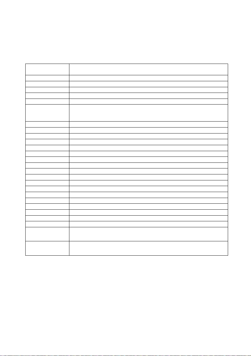
2 Technical Specifications
Power supply voltage, V ................................................................................... 10 - 27
Current consumption, mА, max .............................................................................. 150
Characteristics of AL1, AL2 (terminals Zone1, GND, Zone2):
Voltage across terminals of AL in standby mode, V......................................... 10 - 27
Short-circuit current across AL, mА, max ................................................................. 20
Alarm loop resistance* in kOhms for the following statuses:
- «Normal»............................................................................................................ 3 - 5
- «Violation».......................................................................................... 0 -3 or above 5
Integration time AL1, ms..................................................................................300 ± 30
Integration time AL2, ms..................................................................................500 ± 50
Resistance in wires connected to AL
(exclusive remote mounted units), Ohm, max......................................................... 220
Leakage impedance between wires in AL or
each wire and “Ground”, kOhm, min......................................................................... 20
Characteristics of Relay1 output:
Maximum load voltage AC, V.................................................................................. 250
Maximum load voltage DC, V ................................................................................... 30
Maximum load current AC, DC, А............................................................................... 5
Characteristics of Out output:
Maximum load current, mА ..................................................................................... 100
Maximum load voltage, V.......................................................................................... 27
RS-485 interface line length, m, max................................................................. 1000
Dimensions, mm, max .......................................................................... 174 × 150 × 43
Weight, kg, max..................................................................................................... 0,42