Sensor SMT-200 User manual
Io SENSOR
SMT-200 Operations and Technical Manual 2.00/R1
SENSOR Nederland b.v.
SMT-200 v2.00
Operations and Technical
Manual

Io SENSOR
SMT-200 Operations and Technical Manual 2.00/R1
Page intentionally left blank

Io SENSOR Warranty
SMT-200 Operations and Technical Manual 2.00/R1 i
CERTIFICATION
SENSOR Nederland b.v. - INPUT/OUTPUT INC. certifies that this instrument meets it's published
specifications at the time of shipment from the factory.
WARRANTY AND ASSISTANCE
This INPUT/OUTPUT INC. product is warranted against defects in materials and workmanship for a period of
SIX months from the date of shipment. INPUT/OUTPUT INC. will, at it's option, repair or replace a product
which proved to be defective during the warranty period, provided it is returned to an INPUT/OUTPUT INC.
office and providing the proper preventative maintenance procedures as listed in this manual are followed.
Repairs necessitated by misuse of the product are not covered by this warranty.
NO OTHER WARRANTIES ARE EXPRESSED OR IMPLIED INCLUDING, BUT NOT LIMITED TO, THE
IMPLIED WARRANTIES OF MERCHANTABILITY AND FITNESS FOR A PARTICULAR PURPOSE. IN
NO EVENT SHALL INPUT/OUTPUT INC. BE LIABLE FOR ANY INCIDENTAL OR CONSEQUENTIAL
DAMAGES RESULTING FROM THE USE OF THE PRODUCT OR CAUSED BY ANY DEFECT, FAILURE,
OR MALFUNCTION OF THE PRODUCT, WHETHER A CLAIM FOR SUCH DAMAGE IS BASED UPON
WARRANTY, CONTRACT, NEGLIGENCE OR OTHERWISE.

Software License Io SENSOR
ii SMT-200 Operations and Technical Manual 2.00/R1
SOFTWARE LICENSE
ATTENTION: USE OF THE SOFTWARE IS SUBJECT TO THE I/O SOFTWARE LICENSE TERMS SET
FORTH IN THE INPUT/OUTPUT MASTER SOFTWARE LICENSE AGREEMENT. USING THE
SOFTWARE INDICATES YOUR ACCEPTANCE OF THESE TERMS. IF YOU DO NOT ACCEPT THESE
TERMS, YOU MAY RETURN THE SOFTWARE FOR A FULL REFUND. IF THE SOFTWARE IS
SUPPLIED WITH ANOTHER PRODUCT, YOU MAY RETURN THE ENTIRE UNUSED PRODUCT FOR A
FULL REFUND. YOUR RIGHT TO RETURN AND REFUND EXPIRES 30 DAYS AFTER PURCHASE
FROM I/O OR AN I/O DISTRIBUTOR. THE RIGHT TO RETURN AND REFUND DOES NOT EXTEND TO
YOUR TRANSFEREE.
The following terms govern your use of the enclosed software unless you have a separate Input/Output
master software license agreement in place.
LICENSE Grant- I/O grants you a license to use one copy of the version of the software (identified in your
documentation) on any one hardware product. “You” means the company, entity or individual whose funds
are used to pay the license fee. “Use" means storing. loading, installing, executing or displaying the
software. You may not modify the software or disable any licensing or control features of the software
except as an intended part of the software's programming features
Ownership- The software is owned and copyrighted by I/O. Your license confers no title or ownership in the
software and should not be construed as a sale of any right in the software. I/O's third party suppliers may
protect their rights in the event of any violation of these terms.
Copies and Adaptations- You may only make copies or adaptations of the software for archival purposes
or when copying or adaptation is an essential step in the authorised use of the software. You must
reproduce all copyright notices in the original software on all authorised copies or adaptations. You may not
copy the Software onto any bulletin board or similar system.
No Disassembly or Decryption- You may not disassemble, decompile or decrypt the software unless I/O's
prior written consent is obtained. In some jurisdictions, I/O's consent may not be required for disassembly or
decompilation. Upon request, you will provide I/O with reasonable detailed information regarding any
disassembly or decompilation.
Transfer- Your license will automatically terminate upon any transfer of the software. Upon transfer, you
must deliver the original and all complete, partial or electronically stored copies of the software and related
documentation to the transferee. The transferee must accept these terms as a condition to the transfer.
Termination- I/O may terminate your license upon notice for failure to comply with any of these terms.
Upon termination, you must immediately destroy the software together with all copies, adaptations and
merged portions in any form.
Export Requirements-You may not export or re-export the software or any copy or adaptation in violation
of any applicable laws or regulations.

Io SENSOR Compliance
SMT-200 Operations and Technical Manual 2.00/R1 iii
Year 2000 Compliance
covering electronic equipment and software produced by
IOSENSOR
SMT-100
Transfer Program
Reader Program
The hardware and software used in the ‘SMT-100 Geophone Tester’ and
‘SMT-100 Fieldbox’ (model I and II) does not utilise a real-time clock and is
therefore immune from problems associated with the year 2000 issue. The
date (that can be manually set in the header of the printout) will accept the
year 2000 and higher. Also the associated ‘SMT-100 Module Reader’ and
RS232 data transfer ‘SMT-100 Xfer’ programs (both version 1.84 and higher)
will accept dates beyond 31 December 1999.
See Note
SMT-150
The SMT-150 hardware and associated ‘SMT-150 Geophone Tester’
program (version 1.84 and higher) will accept dates beyond 31 December
1999.
See Note
SMT-200
(Docking Station)
The SMT-200 hardware and software (version 1.89 and higher) and
associated ‘SMT-200DS Docking Station’ program (version 1.89 and
higher) are year 2000 compliant. Please note that during data transfer from or
to the PC and during updates of the SMT-200 program, the time and date of
the SMT-200 is synchronised with the time and date of the host PC.
* To prevent possible date conflicts it is strongly recommended to attach the
SMT-200 only to PC’s that are year 2000 compliant.
* To prevent possible update problems never update the SMT-200 software
from a PC that is not year 2000 compliant.
Note
The hardware and software has been tested on PC’s that are year 2000
compliant. Other than date and time stamp errors on files saved to PC’s that
are not year 2000 compliant, there are no other problems expected when
connected to PCs that are not year 2000 compliant.
IOSENSOR can not be held responsible for the malfunction of the
above programs or loss of data when used on PC’s that are not year 2000
compliant.
Please contact one of our sales offices in case you encounter any problem.
IOSENSOR has adopted the BSI-DISC definition of ‘Year 2000 Conformity’:
“Neither performance nor functionality is affected by dates prior to, during and after the year 2000”

Table of contents Io SENSOR
vi SMT-200 Operations and Technical Manual 2.00/R1
Table of Contents
Page
SECTION 1 INTRODUCTION 1
1.1 Introduction 3
1.2 Technical Support 3
1.3 Overview 4
1.4 Specifications 4
1.5 Packaging information 5
1.6 Before use... 6
1.6.1
Voltage selection 6
1.6.2
Battery charging 6
SECTION 2 SMT-200 OPERATIONS 7
2.1 SMT-200 Layout 9
2.2 Switching on the SMT-200 9
2.2.1
Post Mortem on Powering up 10
2.3 Navigating around the screens 10
2.4 Switching off the SMT-200 13
2.5 Battery level 14
2.6 Battery level Jumper setting 15
2.7 Menu flowchart 16
2.8 Main menu The main menu allows access to all functions of the SMT-200 19
2.9.1
Do a test Select this option to initiate a test sequence on a string 19
2.10.2 Setup menu Allows customisation of the SMT-200 operating and test parameters 20
2.11.2.1 String menu Set the string geometry and leader parameters 20
2.12.2.1.9 Limits menu Sets maximum allowable limits for various tests 21
2.13.2.2 Geophone menu Selects and modifies if required the type of geophone element used 21
2.14.2.2.1 Select menu Selects the type of geophone element used 22
2.15.2.2.2 Edit Edit the geophone parameters 22
2.16.2.2.3 Copy Copy existing element description to a new geophone type 22
2.16.2.2.4 Delete Deletes an existing element description 22
2.17.2.3 Operating menu General options for string testing 23
2.18.2.4 Tests Sequence Selects the tests to be performed on the string 24
2.19.2.5 Display menu Customises display, keypad and sound options 24
2.20.2.7 Power menu Selects the various power saving options 25
2.21.2.8 Date & Time Sets the SMT-200 clock 25
2.22.2.9 Diagnostics Runs the diagnostics and calibration routines 26
2.23.3 Temp. menu Read or set the external temperature and temperature options 28
2.24.4 File menu Internal file handling and data / code transfer options 30
2.25.4.1 Redisplay Last Shows the result of the last test run 30
2.26.4.2 Storage Status Indicates the internal memory storage 31
2.27.4.3 Dump data file Transfer contents of data file to COM port 31
2.28.4.4 List data file List contents of data file 32
2.29.4.5 Erase data Clears contents of data file 32
2.30.4.6 Read Config Loads the stored configuration file 33
2.31.4.7 Save Config Saves the configuration file 33
2.32.6 About Provides general information about the SMT-200 34

Io SENSOR Table of contents
SMT-200 Operations and Technical Manual 2.00/R1 vii
SECTION 3 DOCKING STATION & PC SOFTWARE OPERATIONS 35
3.1 Docking Station overview 37
3.2 Docking Station interconnection 37
3.2.1
Battery Charging 38
3.2.2
PC Interface 38
3.3 Docking Station PC software introduction 39
3.4 Software installation 39
3.5 Windows installation 39
3.5.1
Windows un-install 40
3.6 DOS installation 40
3.6.1
DOS un-install 40
3.7 Running the program 41
3.7.1
SMT-200DS menu 42
3.7.2
File menu 42
3.7.3
SMT-200 menu 42
3.8 Data Exchange 43
3.8.1
Instructions for File Transfer 43
3.8.2
Explanation of Data transfer sequence: 43
3.8.3
The SMT-200 During File Transfer 44
3.8.4
Failing Transfers 44
3.9 System Update 45
3.9.1
Instructions for System Update 45
3.9.2
Failing System Updates 45
3.10
The SMT-200 Geophone Specifications File 45
SECTION 4 RFID TAG READER 47
4.1 RFID Tag reader introduction 49
4.2 Principles of the RFID Tag reader 49
4.3 Working with the RFID Tag reader 50
4.3.1
Read tags 50
4.3.2
Test the strings 51
4.3.3
Transfer data file 52
4.4 Sorting the tag list 53
4.4.1
Download the tag list to the PC 53
4.4.2
Upload the tag list to the SMT-200 53
4.4.3
View the tag list on the SMT-200 55
4.4.4
View the tag list on the PC 55
4.5 Settings 57
4.5.1
COM settings 57
4.5.2
Autonumber 57
4.5.3
Tag menu visible 57
4.6 Internal storage 58
SECTION 5 GEOPHONE TESTING 59
5.1 Preparing the SMT-200 for use 61
5.2 Testing a string 63
5.3 Downloading data to a PC 64
5.3.1
Data File Test codes 65
5.3.2
Data File Reject codes 65
5.4 Basic Geophone Troubleshooting using the continuous impedance test 66
5.5 Isolation Table 69

Table of contents Io SENSOR
vi SMT-200 Operations and Technical Manual 2.00/R1
SECTION 6 SMT-200 TECHNICAL 71
6.1 SMT-200 Description 73
6.2 PC/104 Description 73
6.3 PC/104 Connector and Jumper Locations 74
6.4 SMT-200 Main Board block diagram 75
6.5 Power Supply 76
6.6 Address Decoder 76
6.7 Display 76
6.8 Keyboard 77
6.9 Digital to Analogue Converter 77
6.10
Filter 78
6.11
Geophone Circuit 78
6.12
Analogue to Digital Converter 78
6.13
SMT-200 Interconnection 79
SECTION 7 DOCKING STATION TECHNICAL 81
7.1 Docking Station Block Diagram 83
7.2 PC Interface 84
7.3 Battery Charging 84
APPENDIX A CONNECTOR PIN OUTS 87
A.1 SMT-200 Bendix Connector 89
A.2 Docking Station SMT-200 Connector 89
A.3 Docking Station External Smartec Connector 90
A.4 Docking Station PC Connector 90
A.5 Smartec Temperature Sensor 91
A.6 SMT-200 to Docking Station Cable 92
APPENDIX B TEST OVERVIEW 93
B.1 Geophone Basics 95
B.2 Polarity Test 95
B.3 Noise Test 96
B.4 Leakage Test 96
B.5 Resistance Test 97
B.6 Pulse Test 97
B.7 Distortion Test 99
B.8 Distortion test drive mode 100
B.9 Continuous Impedance 100
B.10
Low Drive Continuous Impedance 100
B.11
Geophone String Resistance Calculation 101
B.11.1 Series String 101
B.11.2 Series Parallel String 101
B.12
Damping Calculations 102
B.13
Temperature Compensation 102
APPENDIX C PARTS LIST 103
C.1 SMT-200 Geophone Tester 105

Io SENSOR Table of contents
SMT-200 Operations and Technical Manual 2.00/R1 vii
C.2 SMT-200 Battery Pack 109
C.3 SMT-200 Docking Station 110
C.4 SMT-200 Accessories and Cables 112
APPENDIX D SCHEMATICS & LAYOUTS 113
D.1
SMT-200 Schematics 115
D.1.1 SMT-200 Geophone Tester 115
D.1.2 SMT-200 ADC 116
D.1.3 SMT-200 Filter 117
D.1.4 SMT-200 Keyboard 118
D.1.5 SMT-200 DAC 119
D.1.6 SMT-200 Geophone Circuit 120
D.1.7 SMT-200 Power 121
D.1.8 SMT-200 Display 122
D.2 SMT-200 Component Layout (SMT-200.7 01/98) 123
D.3 SMT-200 Docking Station Schematics 124
D.3.1 SMT-200 Docking Station / Charger 124
D.3.2 UC3906-B1 125
D.3.3 UC3906-B2 126
D.4
SMT-200 Component Layout (SMT-200.7 CHARGER 01/98) 127
APPENDIX E QUICK REFERENCE 129
E.1
Quick Reference 131
APPENDIX F ADDENDUM 135
F.1
Addendum 137
INDEX 139

Table of terms Io SENSOR
viii SMT-200 Operations and Technical Manual 2.00/R1
Table of terms
Symbol Denotation
% Percent
Ω
ΩΩ
ΩOhm
ºC Degrees Centigrade
ºF Degrees Fahrenheit
Bo Open circuit damping
Bc Coil damping
Bt Total damping
FFT Fast Fourier Transfer
Fn Natural frequency
Go Open circuit sensitivity
Hz Hertz
Kg. Kilogram
Lbs. Pounds
M Suspended mass
mm Millimeters
m Meters
MB Mega byte
Rc Coil resistance
Rs Shunt resistance
Rt Total geophone resistance
V Volts
v Software version
V/in/s Volts per inch per second
V/m/s Volts per meter per second
VAC Volts alternating current

Io SENSOR Section 1 Introduction
SMT-200 Operations and Technical Manual 2.00/R1 1
Section 1
Introduction

Section 1 Introduction Io SENSOR
2SMT-200 Operations and Technical Manual 2.00/R1
Page intentionally left blank

Io SENSOR Section 1 Introduction
SMT-200 Operations and Technical Manual 2.00/R1 3
1.1 Introduction
These instructions are intended as a guideline for the operation of the SMT-200 Geophone Tester. Should
problems be found that cannot be answered by these notes please call your nearest I/O Sensor Technical
Support location for assistance.
The availability of future software upgrades will be made known to SMT-200 users via the i-o web site.
Your comments regarding the convenience of operation of the unit, its performance, any problems you have
experienced and any features that would be useful or are in your opinion essential, would be greatly
appreciated for the future development of this product.
The software provided with this tester is proprietary and may not be copied without prior consent having
been obtained from Sensor Nederland b.v.
1.2 Technical Support
Further information and assistance can be obtained by calling one of the following I/O SENSOR Technical
Support locations:
EUROPE
Sensor Nederland bv.
Rouwkooplaan 8
2251 AP Voorschoten
Holland
Tel. +31 (0)71 5601234
Fax. +31 (0)71 5617145
Contact and e-mail address:
Kees Faber (kfaber@i-o.com)
USA & CANADA
Input/Output
11104 West Airport
Stafford
Texas 77477 USA
Tel. +1 281 879 2130
Fax. +1 281 879 3500
Contact and e-mail address
Scott Williams (swilliam@i-o.com)
See our web site at www.i-o.com for SMT-200 updates, geophone specifications and information on other
I/O products.

Section 1 Introduction Io SENSOR
4SMT-200 Operations and Technical Manual 2.00/R1
1.3 Overview
The SMT-200 is the latest addition to the Sensor range of geophone testing equipment. Due to the
advanced technology used in the design it has all the features of previous generation testing
equipment in a smaller and more compact unit. Its easy to use menu system allows the SMT-200 to be
quickly configured to test virtually any type of geophone string. Internal automatic calibration
eliminates the need for regular maintenance.
The Docking station is provided to manage battery charging and communication between the
SMT-200 and the PC.
The SMT-200 can be operated from lead-acid gel batteries (2 supplied) or connected to the docking
station for file transfer. The battery pack will supply enough power for 4 hours heavy field use.
1.4 Specifications
Natural Frequency
Range 1 to 100Hz
Accuracy < 8Hz ± 2% of measured value or 0.1Hz whichever is the greater
8Hz - 14Hz ± 0.5% of measured value or 0.05Hz whichever is the greater
>14Hz ± 1% of measured value
Display Resolution 0.01Hz
Coil Resistance
Range 20 to 9999 ohm
Accuracy ± 1% or 1 ohm whichever is the greater
Display Resolution 1 ohm or 0.1 ohm when measured value is less than 100 ohm
Damping
Range 0.100 to 0.850
Accuracy ± 1% of measured value
Display Resolution 0.001
Sensitivity
Range 0 to 999 V/m/s
Accuracy ± 2% Calculated from other measured values
Display Resolution 0.1 V/m/s
Harmonic Distortion
Range 0 to 20 %
Accuracy ± 10% of measured value or 0.01% whichever is greater
Display Resolution 0.01%
Dynamic Resistance
Range 20 to 99999 ohm
Accuracy Not specified

Io SENSOR Section 1 Introduction
SMT-200 Operations and Technical Manual 2.00/R1 5
Leakage Test
Range 1M to 100M ohm (measured at 5V max)
Accuracy ± 5% of measured value (after calibration)
Test Storage
Capacity 2 MB FLASH disk typically storing 16000 records
Actual figure will depend on tests selected and tags stored
Physical Characteristics
Dimensions (Approx.) 270 x 110 x 60 mm (10.63 x 4.33 x 2.36 inches)
Weight (Approx.) 1.5 kg (3.30 lbs.)
Environmental Specifications
Operating temperature range -20 to 60 °C ( -4 to 140 °F)
Storage temperature range -40 to 70 ° C (-40 to 158 °F)
NOTE: All capabilities are measured at 20 °C.
1.5 Packaging information
Before getting started please check the package is complete with the following items:
• Transport case
• SMT-200 including carry strap
• Two Battery packs
• Docking Station
• Reference geophone SM4/U-B 10Hz 375 ohm
• Geophone cable Bendix to unterminated incl. temp sensor in Bendix connector
• Cable SMT-200 to Docking Station, Bendix-C24
• Serial cable D9 to D9
• Serial adaptor D9 - D25
• Mains cable (Euro / US / or UK)
• Leakage probe
• Temperature probe
• Spare fuse 500 mA 250V
• Software diskette SMT-200 v2.00 & Docking station programs
• Operations and Technical Manual (this Manual)
• Certificate of calibration
Section 1 Introduction Io SENSOR
6SMT-200 Operations and Technical Manual 2.00/R1
1.6 Before use...
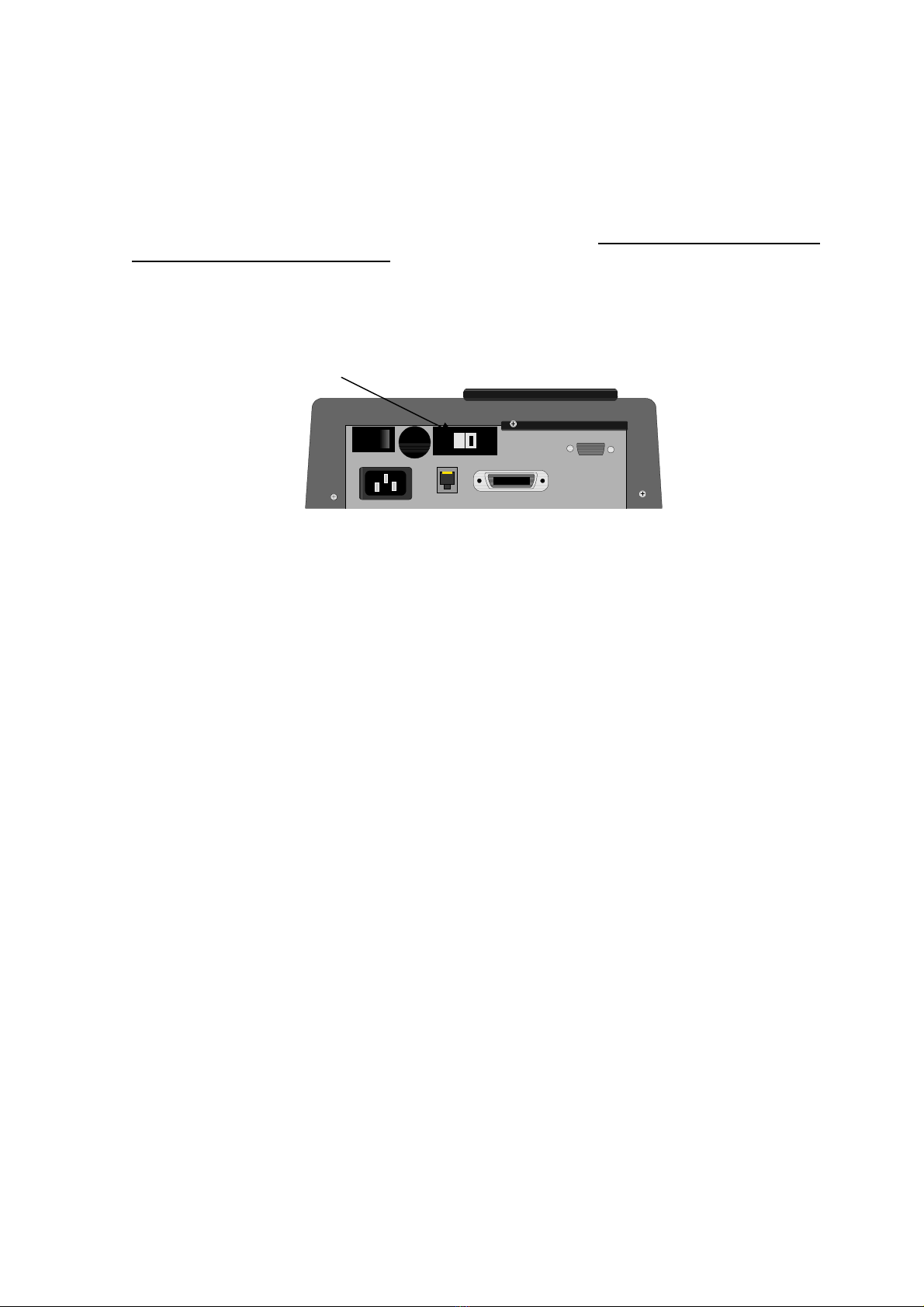
1.6.1 Voltage selection
The docking station requires connection to a suitable power source. THE SELECTION OF 115 V OR
230 V MUST BE DONE MANUALLY.Moving a red switch on the rear of the docking station to the
appropriate position does this (Docking Station is always shipped with 230 V selected). The docking
station is designed to work between 50 Hz to 60 Hz AC so no switching for this is necessary.
Voltage Selector Switch 110 / 230 V
1.6.2 Battery charging
The battery supplied is a maintenance free 1.2 AH Lead Acid Gel Cell. This type of battery can be
used in any position and features a low ‘self discharge’ which means it can be left unused for some
time without requiring recharging. Due to the sealed nature of the battery it should only be recharged
on the supplied docking station. The battery could be destroyed if it is recharged with the incorrect
type of charging unit. To ensure maximum performance from the battery the following guidelines
should always be followed:
• Do not leave the battery discharged for extended periods
• Never short circuit the terminals
• If possible avoid charging battery pack at extreme ambient temperatures
Remove battery pack from the SMT-200 and store safely if the SMT-200 is not to be used for an
extended period of time

Io SENSOR Section 2 SMT-200 Operations
SMT-200 Operations and Technical Manual 2.00/R1 7
Section 2
SMT-200 Operations

Section 2 SMT-200 Operations Io SENSOR
8SMT-200 Operations and Technical Manual 2.00/R1
Page intentionally left blank
Io SENSOR Section 2 SMT-200 Operations
SMT-200 Operations and Technical Manual 2.00/R1 9
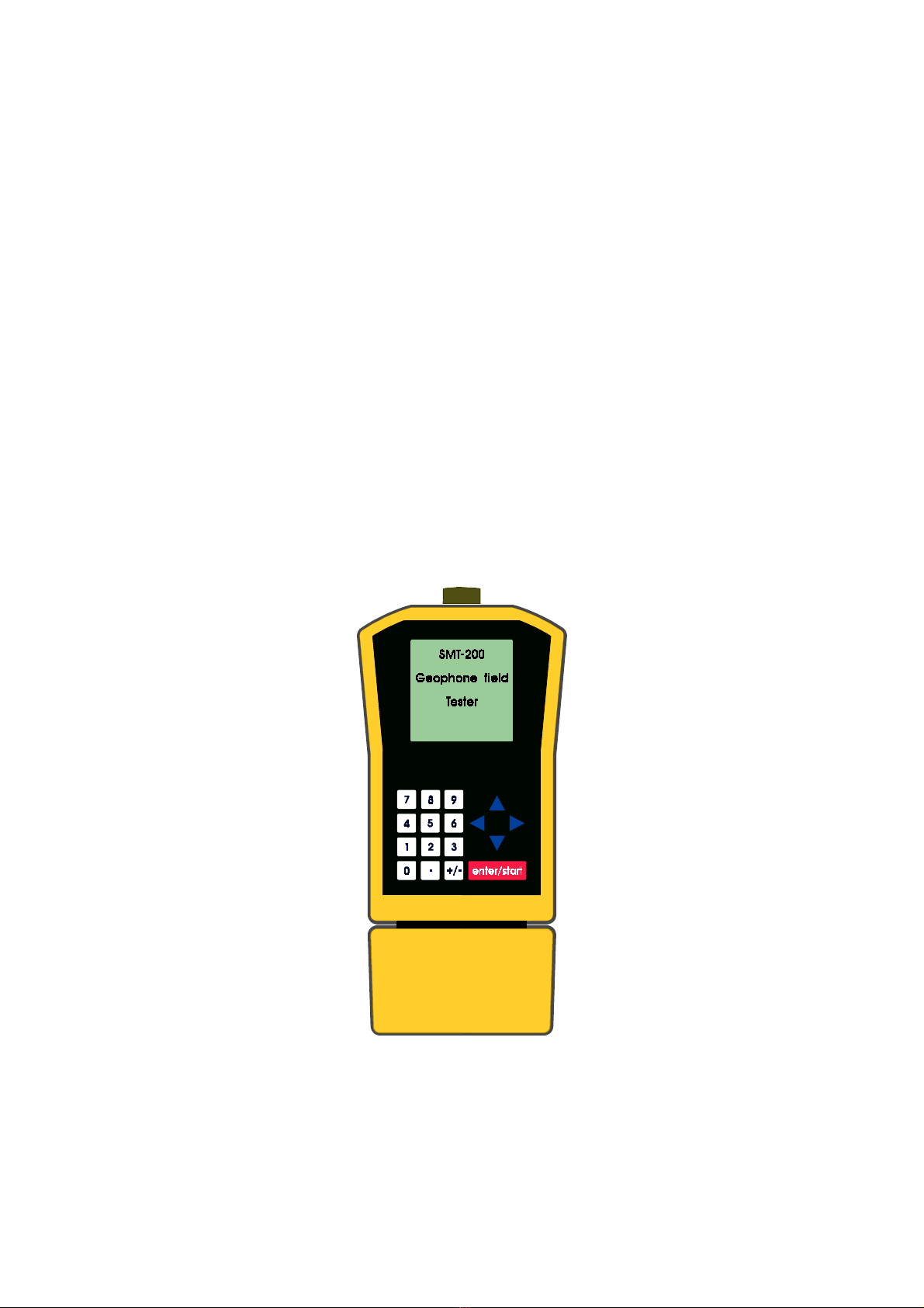
2.1 SMT-200 Layout
The SMT-200 consists of two parts, the main case and a removable battery pack. The battery pack
must be connected for mobile operation. Operation is still possible when connected to the supplied
docking station, in which case the battery does not need to be connected. If the battery pack is
attached to the main body the docking station will be monitoring the battery and will be automatically
charging the battery as required.
2.2 Switching on the SMT-200
To power up the SMT-200 simply push the ENTER/START key once. The unit
will beep to acknowledge the power up request. The start up screen will be
displayed while the system is going through a set of Power On Self Tests
(POST). This is a functional test of the CPU and its associated hardware.
After approximately 20 seconds the unit will beep once and the main menu
will appear after a further 20 seconds. The unit is now ready for operation. If
this is the first time the unit has been used it will need to be setup for the
particular strings to be tested. All settings are stored in non-volatile memory
and are retained even when the power is off.
SENSOR
SMT-200
GEOPHONE TESTER
Booting...
SENSOR
Nederland b.v.
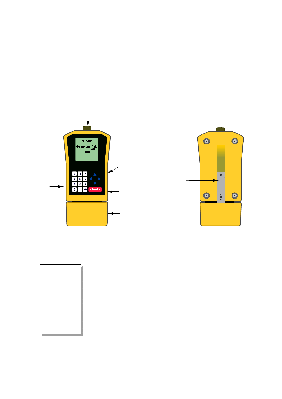
SMT-200 Front View SMT-200 Rear View
Connector for Geophone string,
Docking Station or Tag reader
Backlit LCD Display
Cusor Keys
Power on &
Start/Enter Key
Battery Pack
Numeric
Keypad
Battery
Lever
Section 2 SMT-200 Operations Io SENSOR
10 SMT-200 Operations and Technical Manual 2.00/R1
2.2.1 Post Mortem on Powering up
If the SMT-200 was last shutdown with one of the following errors, a
post mortem screen is displayed on the next power up sequence
to alert the operator.
Temperature High SMT-200 detected an internal temperature
greater than 80°C
Temperature Low SMT-200 detected an internal temperature
lower than -40°C
Battery Low SMT-200 detected a battery voltage less
than 10.7 V
Shut Down Error Abnormal shut down (e.g. battery removed)
2.3 Navigating around the screens
The SMT-200 operates on a simple menu system. There are two ways to access the sub-menus:
CURSOR CONTROL Use the cursor keys to move to the required sub-
menu. Once the cursor is next to the selected menu hit the
ENTER/START key to select the sub-menu. The down and right
cursors move down the screen and the up and left cursors move
up the screen.
DIRECT CONTROL Hit the number corresponding to the desired sub-
menu on the numeric keypad. This will take you directly to the
required menu.
NOTE: The Tag Reader 5is an SMT-200 optional extra. If not used all
menu items related to this feature can be removed from SMT-200
menu item display via the Docking Station Option screen.
For example Redisplay last is item 1 on the File menu. This particular option will display the last test
record that was recorded. From the Main menu press 4 to take you to the File menu. Press 1 to
directly enter the Redisplay last option. Press 0 to return to the File menu and 0 again to return you
to the Main menu. With a little practice this gives you a fast and powerful way of accessing the menu
items.
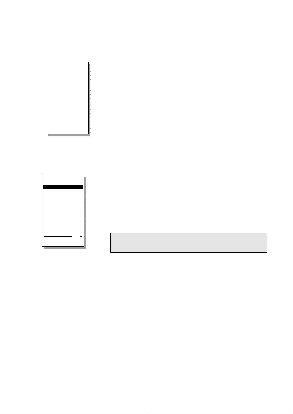
Main menu
----------------
1>Do a test...
2 Setup menu...
3 Temp. menu...
4 File menu...
5 Tag menu...
6 About...
0 Shut down
Enter test mode
!!!!!!!!!!!!!!!!
The SMT-200
was not properly
shut down
Shut Down ERROR!
18/11/99 12:35
Press any key
to continue
!!!!!!!!!!!!!!!!
Table of contents


