TQC Sheen SP4500 User manual
Automatic Cupping Tester
SP4500
V1.0-1219
Operating Instructions (V1.0 1119)
IMPORTANT! Before taking this instrument
in use we strongly advise you to read this
manual carefully.

| 2
TQC Sheen will grant a warranty for a period of 12 months for the Automatic
Cupping Tester and 12 months for all related equipment from the date of
delivery in respect of any evidence of faulty workmanship and materials.
Should a delivered consignment prove to be contrary to contract upon
inspection, the customer shall grant TQC Sheen the opportunity hereunder
of removing the fault, or else the customer may demand replacement.
Because of size and weight of the instrument TQC Sheen will strive to give
remote support.
Should the supply or delivery of any improvement or replacement not prove
possible, the customer may choose between having the purchase price
reduced or in demanding the contract of sale to be rescinded (conversion).
Damage resulting from natural wear and tear, mechanical or chemical
damage, an act of God or non compliance with the operating instructions
shall be excluded from the warranty as well as mechanical interference by
the customer or by third parties with Automatic Cupping Tester and related
equipment without TQC Sheen’s written permission. No liability will be
accepted for defects, damage or injury caused due to use not carried out in
accordance with the manufacturer’s user instructions.
To claim warranty, the rejected product has to be sent to TQC Sheen
together with the original invoice, any exchange before the product has
been returned to TQC Sheen is not possible. TQC Sheen reserve the right to
repair, exchange or supply an equivalent substitute. TQC Sheen is not liable
for handling or transport costs. Warranty on the purchase price is limited, all
liability for consequential damages or changes in technology is expelled.
This product complies to
- Machinery Directive 2006/42 / EC
- Low Voltage Directive 2006/95 / EC
- EMC Directive 2004/108 / EC
This product is RoHS 2 compliant (2011/65/EU)
WARRANTY

3 |

| 4

5 |
INDEX
8 MENU DISPLAY INFORMATION AND OPERATION 14
8.1 Start screens after switch on 14
8.2 Dashboard 14
8.3 Run Setup 14
8.3.1 Run Setup – Manual mode 14
8.3.2 Run Setup – Custom mode 15
8.3.3 Run Setup – Optics Adjustment 16
8.3.4 Run Setup – Statistics 16
8.4 Instrument Setup 18
8.4.1 Instrument Setup – Language 18
8.4.2 Instrument Setup – Units 18
8.4.3 Instrument Setup – Power Management 19
8.4.4 Instrument Setup – Date Time 20
8.4.5 Instrument Setup – Volume 21
8.4.6 Instrument Setup – System Information 21
8.5 Calibration 21
8.5.1 Calibration – History 22
8.5.2 Calibration – Interval 22
8.6 Protect/Login 22
8.7 Run 23
8.7.1 Run – Custom mode 23
8.7.2 Run – Manual mode 24
9 OPERATION 25
9.1 Preparatory Work 25
9.2 Performing a Cupping Test 25
9.3 Start the instrument 25
9.4 Warning signals 25
10 CARE AND MAINTENANCE 26
10.1 Inspection and Maintenance 26
10.2 Disposal of Materials 26
10.3 Customer Service 26
11 ANNEX A | How to Install LD6182 USB Microscope 27
1 GENERAL 7
1.1 Importance of operating manual 7
1.2 User-responsibility 7
1.3 Responsibility of personnel 7
1.4 Dangers 7
1.5 Designated purpose 7
1.6 Copyright 7
1.7 Manufacturer’s/Supplier’s address 7
2 SAFETY INSTRUCTIONS 8
2.1 Meaning of Symbols 8
2.2 Availability of Safety Information 8
2.3 Training of Personnel 8
2.4 Dangers from Electrical Energy 8
2.5 Points of Special Danger 8
2.6 Care, Maintenance, Repairs 8
2.7 Modications to the Equipment 8
2.8 Cleaning of the Instrument and Disposal of Materials 8
3 TRANSPORT AND STORAGE 9
3.1 Packing 9
3.2 User: Check on Receipt 9
3.3 Reporting Transport Damage and Documentation 9
3.4 Storage and Protective Measures when not in use 9
4 INSTRUMENT DATA 10
4.1 Name / Article 10
4.2 Scope of Supply 10
4.3 Technical Data 10
4.4 Dimensions and Weight 10
4.5 Basic Unit 10
4.6 Accuracy 10
4.7 Noise Level 10
4.8 Optional accessoires 10
5 INSTALLATION AND ASSEMBLY 11
5.1 Installation and Operation 11
5.2 Preparation of Energy Connections
11
6 INSTRUMENT CONTROLS AND FUNCTIONS 12
7 INSTRUMENT PREPARATIONS 13
7.1 Test Panels 13
7.2 Calibration plate 13
7.3 Optical tool xture rod 13
7.4 Panel clamp 13

| 6

7 |
1 GENERAL
1.1 Importance of operating manual
This manual is written in order to become familiar with all the functions and
possible applications of the instrument. It contains important instructions
about how to use the instrument safely and economically; according to
the purpose designated. Following these instructions is not only essential
to avoid risks. It also reduces repair costs and down-time and increases the
products reliability and service-life.
Anyone who works with the instrument should follow the instructions in this
manual, particularly the safety related instructions. Additionally local rules
and regulations relating to environmental safety and accident prevention
should be observed.
1.2 User-responsibility
The user should
• Only allow persons to work with the instrument who are familiar
with the general instructions on how to work safely and to prevent
accidents. The use of the instrument should have been instructed
duly The safety chapter and the warnings in this manual should have
been read and understood; acknowledged as evidenced by their
signature.
• regularly check the safety-awareness of personnel at work.
1.3 Responsibility of personnel
Before commencing work anyone appointed to work with the instrument
should pay attention to the general regulations relating to working safety
and accident prevention. The safety chapter and the warnings in this manual
should have been read and understood; acknowledged as evidenced by their
signature.
1.4 Dangers
This instrument has been designed and constructed in accordance with
state-of-the-art technology and the acknowledged safety regulations.
Nevertheless, working with the instrument may cause danger to the life and
health of the operator or to others, or damage to the instrument or other
property. Therefore the instrument should only be used for its designated
purpose, and in a perfect technical condition. Any defect that could have a
negative eect on safety should be repaired immediately.
1.5 Designated purpose
The TQC Sheen Automatic Cupping Tester is exclusively designed to perform
cupping tests on painted and coated test panels as described within the
specications.
Other applications constitute improper use. TQC Sheen will not be held liable
for damage resulting from improper use.
Designated purpose also includes properly observing all instructions in the
operation manual, and adherence to inspection and maintenance schedules.
1.6 Copyright
The copyright of this operating manual remains with TQC Sheen.
This operating manual is intended solely for the user and his personnel. Its
instructions and guidelines may not be duplicated, circulated or otherwise
passed on to others, neither fully, nor partly. Infringement of these restrictions
may lead to legal action may be taken if this restrictions are infringed upon.
1.7 Manufacturer’s/Supplier’s address
TQC Sheen
Molenbaan 19,
2908LL Capelle aan den IJssel
The Netherlands,
T +31 (0)10 7900 100
F +31 (0)10 7900 111

| 8
2 SAFETY INSTRUCTIONS
2.6 Care, Maintenance, Repairs
• Always make sure the instrument is connected to an earthed socket.
• Maintenance and inspection should be carried out at the correct
intervals
• Operating personnel should be informed before starting with main-
tenance or repair work
• Always make sure the instruments power is turned o and the in-
strument is not connected to a socket while adjusting any electrical
component whenever maintenance, inspection or repair work is
done.
• Do not open the instrument. In case of malfunction always consult
the manufacturer.
2.7 Modications to the Equipment
• Any modications or additions or alterations to the instrument may
solely be made with permission from the manufacturer.
• All measures involving modications require written conrmation of
approval from TQC Sheen
• Instruments which are not in fault-free condition must immediately
be switched o
• Only use replacement parts from the original supplier. Parts used
from other sources aren’t guaranteed to take the loading and meet
the safety requirements.
2.8 Cleaning of the Instrument and Disposal of Materials
• When in use it is not always possible to avoid some spill of paint on
the work surface.
• Try to keep the instrument as clean as possible to prevent distor-
tions of functions.
• To clean the instrument properly use a suitable solvent to dispose
remains of paint or ink.
• Wear gloves during cleaning; Don’t spill an overdose of solvent
during cleaning.
• Cleaning materials must always be used and disposed of correctly.
2.1 Meaning of Symbols
The following symbols for dangers are used in this instruction manual.
Symbol Explanation Warning
Danger
Possible immediate danger to
the life or health of personnel
If this guideline is not noted
it can lead to severe danger
to health,
Warning
A dangerous situation could
be caused
Non observance of this
guideline can lead to injury or
to damage to equipment.
Special tips and particular
information
Guidelines to make optimal
use of the instrument.
2.2 Availability of Safety Information
The instruction manual should be kept at the place where the instrument
operates.
In addition to the information contained in the instruction manual, general
and local regulations for accident prevention and environmental protection
shall be kept available and observed.
Always ensure all guidelines in respect of safety and dangers on the
instrument are in readable condition.
In case of danger the instrument has to be switched o by means of the
emergency-button on the front of the instrument. Then eliminate danger.
2.3 Training of Personnel
• Anyone who operates the instrument should be trained properly.
• It has to be clear who has which responsibility regarding com-
missioning, set-up of maintenance and repairs, installation, and
operation.
• Anyone who hasn’t nished training should be supervised by an
experienced person while working with the instrument.
2.4 Dangers from Electrical Energy
• Work on the electrical supply may only be done by a qualied
electrician.
• The electrical equipment of the instrument must be checked
regularly. Loose connections and cable damaged by heat must be
corrected immediately.
• Always make sure the instrument’s power is turned o while adjust-
ing any electrical component.
2.5 Points of Special Danger
There are some points of special danger:
• Always have the adjustable test cylinder head locked
in place prior to and during testing Keep your hands
away from the working area after the instrument has
started!
• Never put your ngers / hand in the sample holder
Danger

9 |
3 TRANSPORT AND STORAGE
3.1 Packing
Please take note of pictorial symbols on the packing.
3.2 User: Check on Receipt
Check packing for damage
After unpacking check complete supply.
3.3 Reporting Transport Damage and Documentation
Any damage should be documented as accurately as possible (possibly
photographed) and reported to the relevant insurers or, in the case of sales
“delivered to customers works”, to the
supplier.
3.4 Storage and Protective Measures when not in use
The instrument must be stored in a dry place at a temperature between 10
- 40°C.
The storage period should not be longer than 3 months.
Store instrument in the original packing if possible.

| 10
4 INSTRUMENT DATA
4.1 Name / Article
TQC Sheen Automatic Cupping Test – Microprocessor Controlled Automatic
Cupping Test
4.2 Scope of Supply
• TQC Sheen Automatic Cupping Test
• Power cord
• Calibration plate
• Loupe & Microscope xture rod
• Reference panel
• Manual
• Calibration Certicate
4.3 Technical Data
Indenter Speed: 0.01 - 0.70 mm/s
Stroke length: 0 - 12 mm
Max panel width: 105 mm
Max. panel thickness steel: 0.8 mm
Max. speed steel panel: 0.6 mm/s
Max. panel thickness aluminium: 1.2 mm
Max. speed aluminium panel: 0.7 mm/s
.
4.4 Dimensions and Weight
Depth: 390 mm
Width: 355 mm
Height: 450 mm
Net weight: approx. 29 kg
4.5 Basic Unit
Power Supply: 100 – 240 VAC, 50 - 60 Hz
Power consumption: max. 80 Watt
Display: Full Color 480 x 272 pixel TFT display
Safety: Emergency button, integrated acoustic
alarm
Function: 5-key navigation switch with Triple I
Control
4.6 Accuracy
Indenter Speed accuracy: +/- 1% of set speed
Stroke length accuracy: +/- 0.01 mm or 0.2% ever is greater
4.7 Noise Level
The continuous noise level from the instrument does not exceed 70 dB.
4.8 Optional accessoires
SP4331 Calibration plate (105mm)
LD6182 USB microscope
SP4375 Foil clamp

11 |
5 INSTALLATION AND ASSEMBLY
5.1 Installation and Operation
The instrument has to be installed in a suitable place, preferably on a sturdy
table or work area, with normal ambient temperature. Special xings are not
required.
Carefully unpack the apparatus and the accessories and check complete
supply.
Place, if necessary, a spirit level on the work surface and adjust the height of
the feet.
5.2 Preparation of Energy Connections
The instrument is equipped with a safety tested mains supply cable and may
only be connected to plug sockets with earth connection complying with
the safety regulations.
The mains connection is located at the rear of the instrument. Plug in the
female plug in the socket on the rear of the housing. The ON/OFF Switch is
located at the right hand site near the end of the instrument.
The power switch is a digital“ toggle”switch, which always stays in
the same position.
| 12
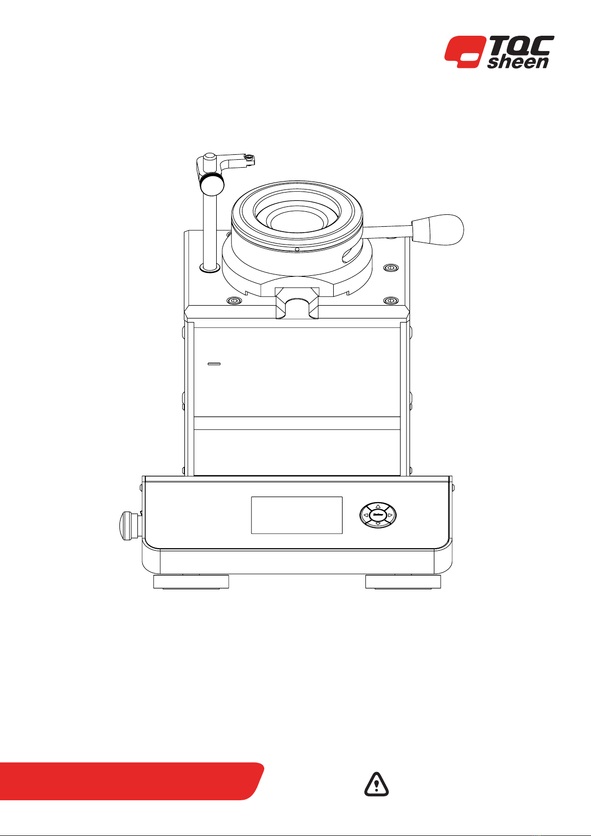
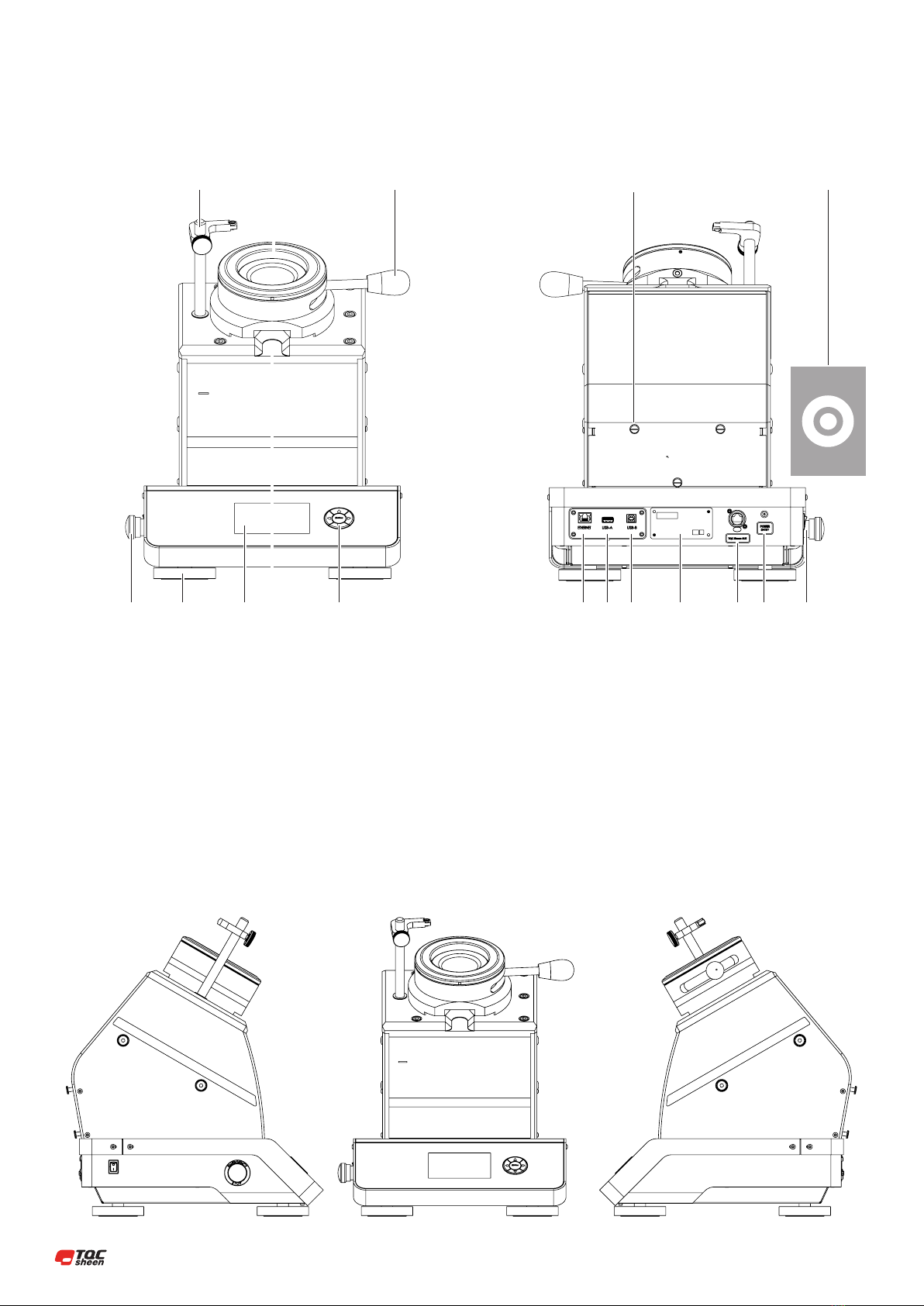
6 INSTRUMENT CONTROLS AND FUNCTIONS
1 Microscope support rod
2 Panel clamp with LED ring
3 Brake and lock for sample holder
4 Emergency button
5 Levelling supports
6 Display with process information
7 Panel slot
8 5-key navigation switch
9 Calibration plate holder
10 Calibration plate
11 Ethernet
12 USB-A
13 USB-B
14 Machine ID-tag
15 TQC Sheen bus
16 Power entry
17 ON/OFF Switch
1 2 3 9 10
4 5 6 7 8 11 12 13 14 15 16 17

13 |
7 INSTRUMENT PREPARATIONS
When using an optional Loupe or USB microscope please insert the supplied
optical tool xture rod in de designated hole according to the instruction
manual.
7.1 Test Panels
We supply a range of test panels
In aluminum or steel in dierent sizes.
All with a protective PE lm.
For more details go to https://www.tqcsheen.com/en/product/knock-out-
testpanels/
7.2 Calibration plate
The TQC Sheen Automatic Cupping Test is supplied with the SP4331
Cupping Test reference board. This specially designed calibration tool is
stowed on the rear of the TQC Sheen Automatic Cupping Test. This precision
engineered reference board allows the user to calibrate the TQC Sheen
Automatic Cupping Test at custom set intervals.
7.3 Optical tool xture rod
Insert the Optical tool (LD6182 USB microscope) xture rod with side with
the length groove rst into the designated hole in the cupping test. After
insertion turn the tool either direction untill it clicks into place. The Optical
tool xture rod is necessary in case you want to use an optional loupe or USB
Microscope (see Annex A).
7.4 Panel clamp
The sample panels are clamped by means of the red handle. This handle is
moved backwards to release the panel and to the front to x the panel.
For use with thin substrates (foils) like metal sheet brass and copper, an
optional foil clamp (SP4375) can be ordered.
Thin substrates tend to curl on the sides and then cannot be removed
properly from the clamping mechanism of the cupping test.
Sliding the foil clamp on top of the sample after the sample has been locked
into the cupping test standard clamping mechanism will
prevent the sample material to curl.
After test the foil clamp is removed and the standard clamp is released where
after the sample can be removed properly.
Art. Nr. SP4375

| 14
8 MENU DISPLAY INFORMATION AND OPERATION
8.1 Start screens after switch on
Switch on instrument by mains switch at the left side on the housing. The
logo is the rst screen shown after switching on the instrument.
After a few seconds the screen appears to press OK to initialize.
8.2 Dashboard
The TQC Sheen Automatic Cupping Test has an advanced menu structure.
The Dashboard allows the user to access all the features available.
8.3 Run Setup
The TQC Sheen Automatic Cupping Test is able to operate in two modes.
Manual and Custom mode. It is also possible to use statistics and adjust the
optics.
8.3.1 Run Setup – Manual mode
Manual Test can be performed to determine when cracks start to appear and
allow the user to start and stop the movement at the indenter at his or her
discrepancy.
The speed has to be entered. The TQC Sheen Automatic Cupping Test is able
to operate at speeds from 0.01 mm/s up to 0.70mm/s. The speed can be set
in 0.01 mm/s increments. The nominal speed according to the ISO 1520 is
0.20 mm/s.
15 |
When operating in manual mode the user only wants to look at the test
panel and should not have to look at the display in order to know how far
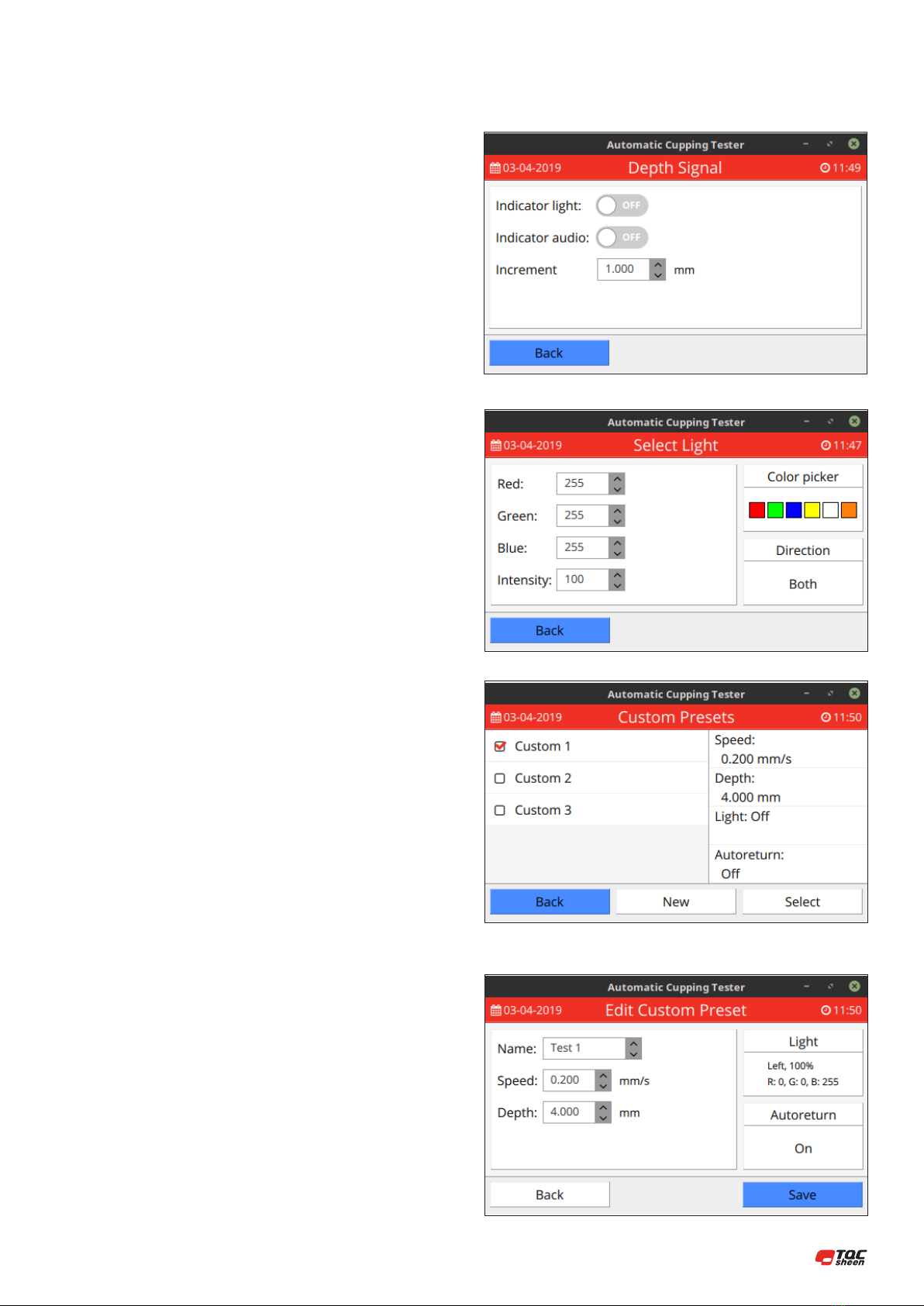
the indentation is. This problem is solved by setting up the Depth signal
menu. The TQC Sheen Automatic Cupping Test can gives visual and audible
warnings at set depth intervals. The increments of the warnings can be set
with the increment op-tion. Audible alarm will be a short beep and the visual
change in light intensity.
One of the most innovative features of the TQC Sheen Automatic Cupping
Test is its ability to produce any colour of light to illuminate the test surface.
Not only enhancing the visibility but also signicantly reducing operator
strain. Either one of the six present colours can be selected.
The intensity setting makes it possible to set the strength of the light. It is
also possible to set the direction of the light. Cracks can best be seen when a
colour complementary to the test panel is used to illuminate the panel.
8.3.2 Run Setup – Custom mode
When the Custom mode is selected the indenter will stop at a set depth.
The Speed has to be entered. The Automatic Cupping Test is able to operate
at speeds from 0.01 mm/s up to 0.70 mm/s. The speed can be set in
0.01 mm/s increments. The nominal speed according to the ISO 1520 is
0.20 mm/s.
One of the most innovative features of the TQC Sheen Automatic Cupping
Test is its ability to pro-duce any colour of light to illuminate the test surface.
Thus not only enhancing the visibility but also signicantly reducing operator
strain. Either one of the six present colours can be selected.
The intensity setting makes it possible to set the strength of the light. It is also
possible to set the direction of the light. Cracks can best be seen when the
complementary colour to the test panel is used to illuminate the panel.
When Custom mode is selected it is possible to use Autoreturn if the indenter
should automatical-ly return to its base position after the set depth is
reached. When used on substrates that are elas-tic or tend to want to recover
to their initial shape the Autoreturn option is best turned o.
It is also possible to change the Names from Custom 1, 2, 3 to any other
desired name.
| 16
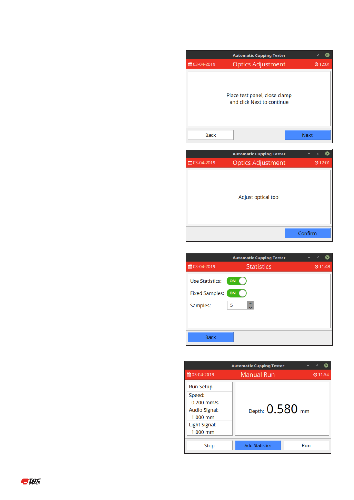
8.3.3 Run Setup – Optics Adjustment
The unique design of the TQC Sheen Automatic Cupping Test allows the user
to use optical availa-ble loupe or USB microscope. The latter has a limited
depth of focus and needs to be adjusted to zero level. In its base position the
indenter is about 0.5mm below the test panel. An USB micro-scope can only
be adjusted when the indenter is against the test panel. In order to bring the
in-denter to its zero position the optical adjustment menu can be used.
When the TQC Sheen Automatic Cupping Test informs you to adjust the
optical tool you are able to adjust the camera. Always adjust the camera on
the panel you are planning to do your test on. The thickness of a panel and
coating will inuence your focus. Select back for the indenter to move back
to their base position.
In the base position both the indenter and the camera focus are 0.5mm
below the panel. The camera support is not xed to one position. It moves
along with the indenter to keep your camera focused on the top of the
indentation, allowing you to always have a perfect picture.
8.3.4 Run Setup – Statistics
You can choose to use the Statistics or not. If you want to choose then you
also can use xed samples or not xed samples.
In manual mode you can add Statistics. If you don’t choose the xed samples
the Statistics will be shown after every single run. If you choose xed samples
the statistics will be shown after the number of samples you select to x.
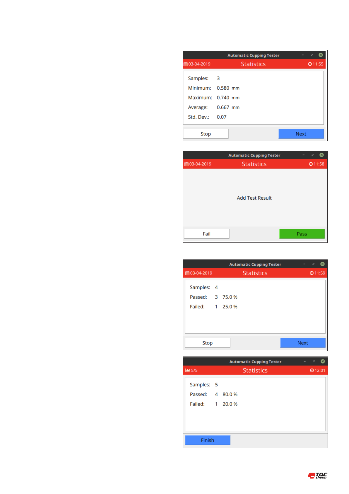
17 |
In custom mode you can also add Statistics where you just can choose Pass
or Fail.
If you don’t choose the xed samples the Statistics will be shown after every
single run.
If you choose xed samples the statistics will be shown after the number of
samples you select to x.
| 18
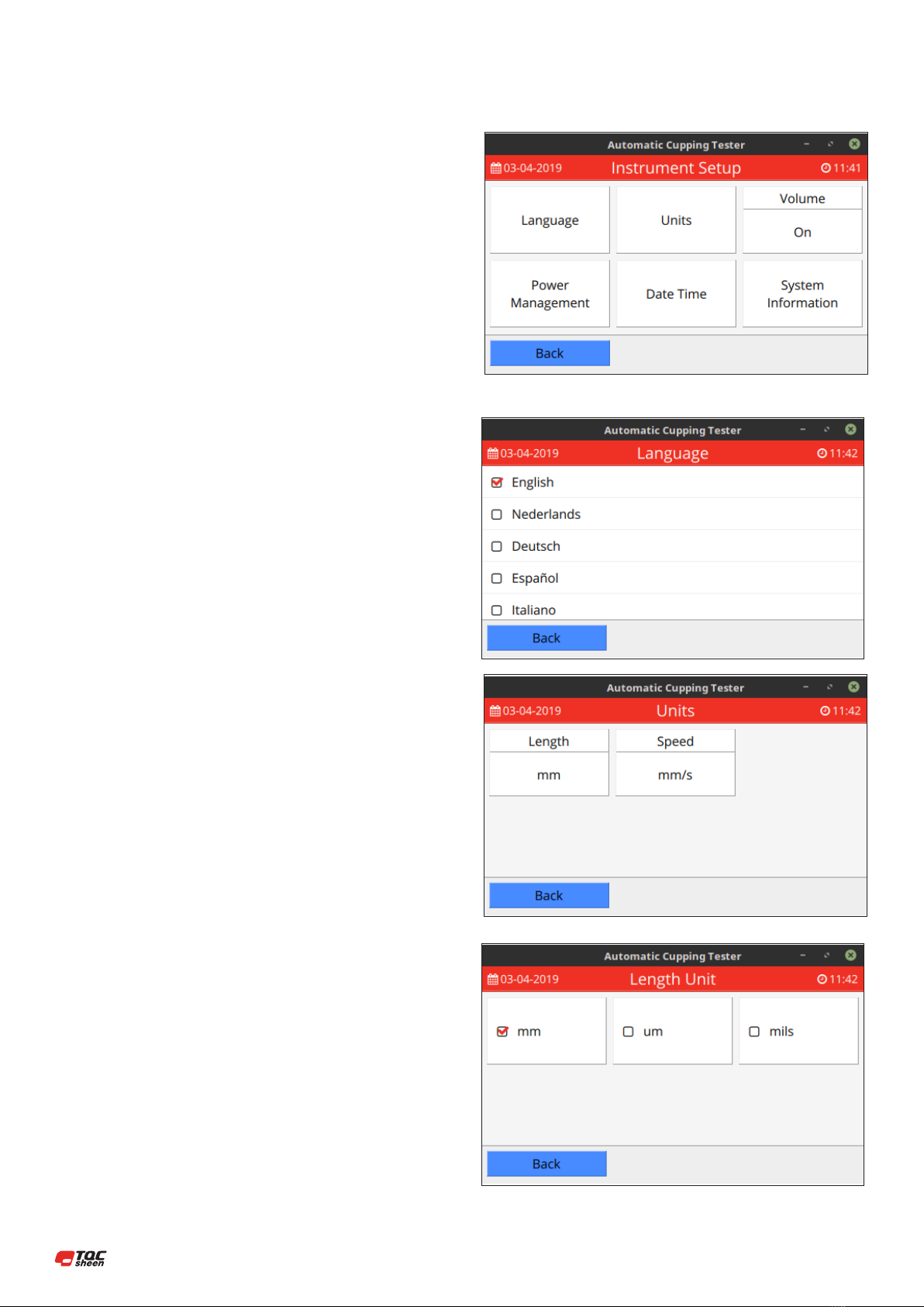
8.4 Instrument Setup
The Instrument Setup menu gives the user access to more advanced settings
allowing him or her to ne tune the instrument to their specications.
8.4.1 Instrument Setup – Language
The TQC Sheen Automatic Cupping Test is equipped with a multi-language
menu. In this part of the menu you can select the desired language. Set the
tick mark in front of the desired language.
8.4.2 Instrument Setup – Units
The units used in the display which are Length and Speed can be set to one of
the three available units. The selected unit will be displayed in all other menus.
19 |
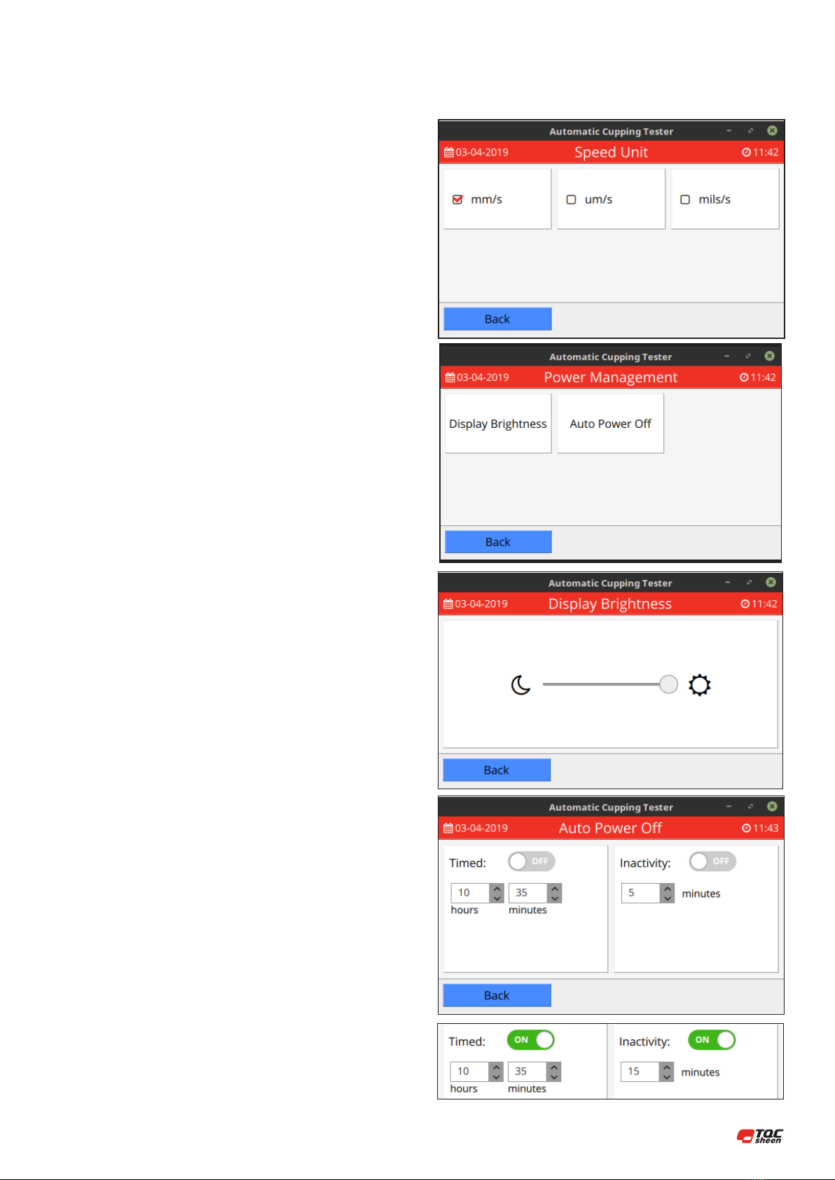
8.4.3 Instrument Setup – Power Management
The display brightness is changeable here.
The TQC Sheen Automatic Cupping Test contains also an Auto Power O
function where it is possi-ble to time when the device turns o automatically
or turns o after a set inactive time.
| 20
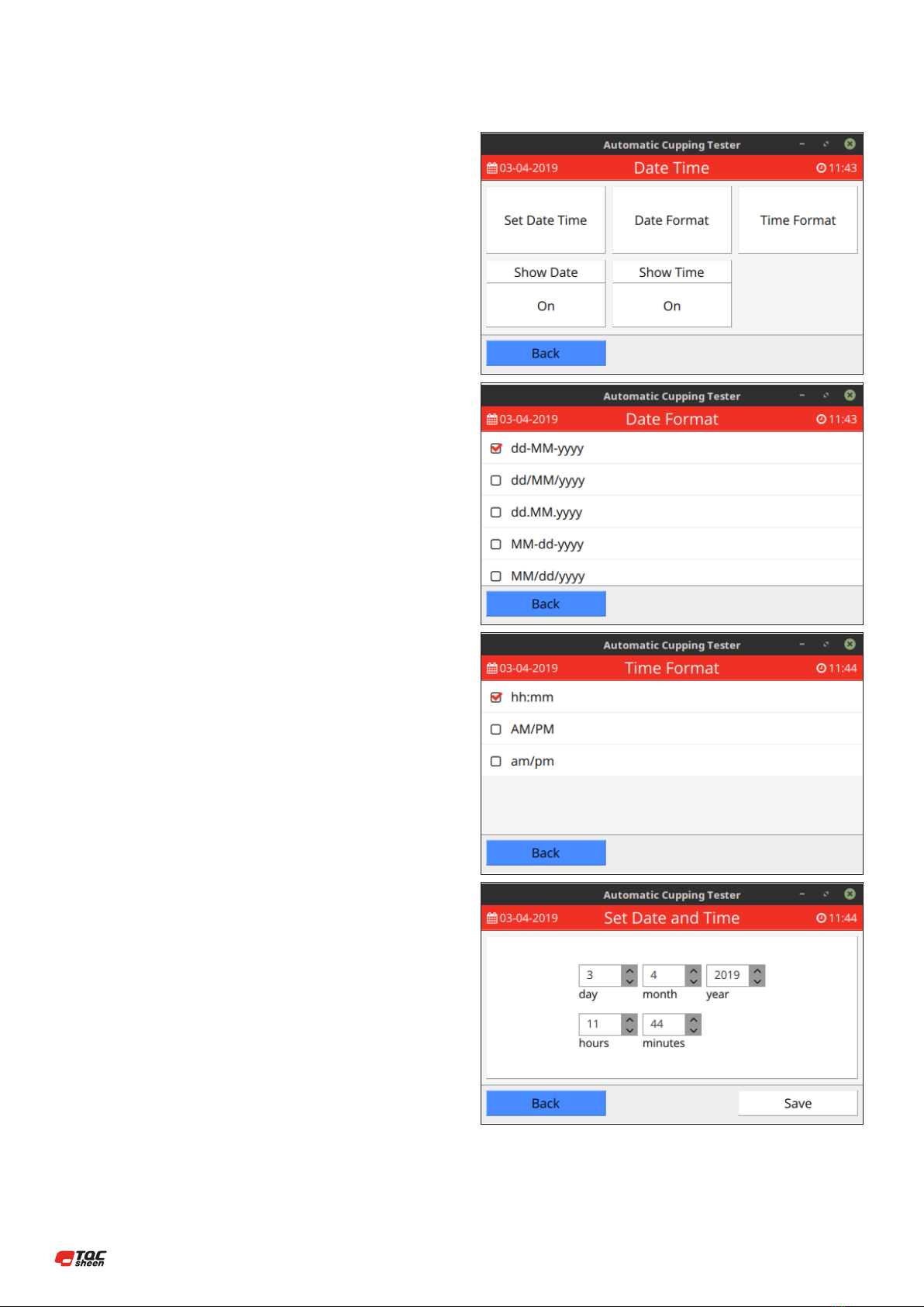
8.4.4 Instrument Setup – Date Time
The TQC Sheen Automatic Cupping Test contains a real time clock to store
the time and date with each calibration. Time and date are also used for
setting the calibration interval. In this menu the time and date can be set by
selecting the desired gure.
Table of contents
Other TQC Sheen Test Equipment manuals

Popular Test Equipment manuals by other brands


Q3 Innovations
Q3 Innovations AlcoHAWK PT500 owner's manual

Tektronix
Tektronix 502 series Service manual

Rohde & Schwarz
Rohde & Schwarz ZN-Z170 technical information

Appion
Appion PTC900 manual

Vanguard Instruments
Vanguard Instruments VBT-75P S2 user manual

DMC
DMC MPT-250B Specification and operating instructions