Sensormate ML1018 User manual

Operating Manual
ML1018
MEASURING LANCE
C-0116_v1.0_ENG

2 / 16 Subject to technical modications

3 / 16
Subject to technical modications
TABLE OF CONTENTS
PREFACE ���������������������������������������������������������������������������������������������������������������������������������������������������4
Device data ..................................................................................................................................... ........4
Warnings and safety........................................................................................................................ ........4
Disposal ...................................................................................................................................................4
Disclaimer........................................................................................................................................ ........4
Copyright ......................................................................................................................................... ........4
WEEE INFORMATION������������������������������������������������������������������������������������������������������������������������ ��������5
1� GENERAL DESCRIPTION ���������������������������������������������������������������������������������������������������������� ��������6
1.1. Prole ................................................................................................................................ ........6
1.2. Construction...................................................................................................................... ........6
1.3. ML1018 Measuring Lance................................................................................................. ........7
2� INSTALLATION ��������������������������������������������������������������������������������������������������������������������������� ��������8
2.1. Preparing for assembly ..................................................................................................... ........8
2.2. Borehole............................................................................................................................ ........8
2.3. Assembly........................................................................................................................... ........9
2.4. Electrical connections ....................................................................................................... ......10
2.5. Reset function ................................................................................................................... ......10
3� OPERATIONS������������������������������������������������������������������������������������������������������������������������������ ������11
3.1. Measurement procedure................................................................................................... ...... 11
4� DISMANTLING ���������������������������������������������������������������������������������������������������������������������������� ������11
5� TRANSPORT AND STORAGE ��������������������������������������������������������������������������������������������������� ������12
6� MAINTENANCE��������������������������������������������������������������������������������������������������������������������������� ������12
6.1. Inspection.......................................................................................................................... ......12
6.2. Servicing ........................................................................................................................... ......12
7� TECHNICAL SPECIFICATIONS ������������������������������������������������������������������������������������������������� ������13
8� ORDER CODES��������������������������������������������������������������������������������������������������������������������������� ������14

4 / 16 Subject to technical modications
PREFACE
Device data
Warnings and safety
Disposal
Disclaimer
Copyright
Note the device serial number, order code and type,
which are listed on the label, here:
• applied on the aluminum cover of the measuring lance
• applied on the aluminum case of the measuring lance
Should you need technical assistance, they must be
communicated to Gefran Customer Service.
Measuring Lance
Serial No.
Order code
Type
Always make sure you have the latest manual version,
that can be freely downloaded from the Gefran website
(www.gefran.com).
The devices illustrated in the manual must be installed by
qualied technicians, following the laws and regulations
in effect and according to the instructions contained in
this manual.
Installation and/or maintenance technicians must read
this manual and strictly follow the instructions herein and
found in the annexes since Gefran cannot be held liable
for personal, property and/or product damages should
the following conditions not be met.
The ML1018 Measuring Lance must be disposed of in accordance with applicable regulations.
Some of the components used in the devices can cause damage to the environment if
incorrectly disposed.
Although all information contained within this document
has been carefully checked, Gefran S.p.A. cannot be
held liable for the possible presence of errors, or damage
to persons or property due to improper use of this
manual.
Gefran S.p.A. also reserves the right to make changes
to the content and form of this document as well as the
characteristics of the illustrated devices at any time
without prior notice.
The technical and performance data indicated in this
manual are to be considered as a guide for the user to
determine the suitability for a certain use, and are not
guarantees. They may be the result of Gefran S.p.A. test
conditions and the user must compare them to his/her
real application requirements.
Gefran S.p.A. cannot be held in any way liable for any
damage to persons or property resulting from IN Sensor
and indicator tampering, incorrect and improper use or
otherwise non compliant with controller features and
instructions in this manual.
This document and its annexes may be freely repro-
duced, provided that the contents are not modied in
any way and each copy includes this warning and the
statement of Gefran S.p.A. ownership.
Gefran and Sensormate are trademarks of Gefran S.p.A.
The document may mention or reproduce trademarks
and logos of third parties. Gefran S.p.A. acknowledges
the ownership of these trademarks or logos by their
respective owners.

5 / 16
Subject to technical modications
WEEE INFORMATION
“Attuazione della direttiva 2012/19/UE sui
riuti di apparec¬chiature elettriche ed elett-
roniche (RAEE)”
Il simbolo del cassonetto barrato riportato sull’ap-
parecchiatura o sulla sua confezione indica che
il prodotto alla ne della propria vita utile deve
essere raccolto separatamen¬te dagli altri riuti.
La raccolta differenziata della presente ap-pa-
recchiatura giunta a ne vita è organizza¬ta e
gestita dal produttore.
L’utente che desideri disfarsi dell’apparec-chi-
atura dovrà quindi contattare il produt¬tore per
ricevere indicazioni sul sistema da quest’ultimo
adottato per consentire la rac¬colta separata
dell’apparecchiatura giunta a ne vita.
L’adeguata raccolta differenziata per l’avvio
successivo dell’apparecchiatura dismessa al
riciclaggio, al trattamento e allo smaltimento
ambientalmente compatibile contribuisce ad
evitare possibili effetti negativi sull’ambiente e
sulla salute e favorisce il reimpiego e/o riciclo dei
materiali di cui è composta l’ap¬parecchiatura.
“Implementation of Directive 2012/19/EU on
waste electrical and electronic equip¬ment
(WEEE)”
The symbol showing a crossed-out wheeled bin
on equipment or its packaging indicates that the
product must be collected separately from other
waste at the end of its useful life.
The manufacturer is responsible for organ¬ising
and managing the separate collection of this
piece of equipment at the end of its useful life.
Users wishing to dispose of the equipment must
therefore contact the manufacturer to obtain inst-
ructions from the same on how to have the equip-
ment collected separately at the end of its useful
life.
By collecting the disused equipment sepa¬rately,
it can be recycled, treated or disposed of in an
environmentally friendly manner, thus helping to
prevent the environment and public health from
being affected negatively and enabling reuse and/
or recycling of the materials forming the same
equipment.
„Umsetzung der Richtlinie 2012/19/EU über
Elektro- und Elektronik-Altgeräte (EEA)“
Das Symbol der durchgekreuzten Mülltonne auf
dem Gerät oder der Geräteverpackung weist da-
rauf hin, dass Sie das Produkt am Ende seines
Lebenszyklus separat entsor¬gen müssen.
Die Getrenntsammlung dieses Geräts an seinem
Lebenszyklusende wird vom Her¬steller organi-
siert und besorgt.
Der Nutzer, der das Gerät entsorgen möchte,
muss sich daher an den Hersteller wenden,
um Auskunft über seine Vorgehensweise zur Ge-
trenntsammlung des Geräts an dessen Lebens-
zyklusende zu erhalten.
Die entsprechende Getrenntsammlung für die
anschließende Zuführung des Altgeräts zum
Recycling, zur Wiederaufbereitung und zur
umweltverträglichen Entsorgung trägt dazu bei,
negative Auswirkungen auf die Umwelt und die
Gesundheit zu unterbinden und begünstigt die
Wiederverwendung und/oder das Recycling von
Werkstoffen, aus denen das Gerät besteht.
“Transposition de la Directive 2012/19/UE re-
lative aux déchets d’équipements électriques
et électroniques (RAEE)”
Le pictogramme de la poubelle barrée, gu¬rant
sur l’équipement ou sur son emballage, indique
que le produit en n de vie doit être traité séparé-
ment des autres déchets.
Le ramassage sélectif de cet équipement en n
de vie est organisé et géré par le constructeur.
Tout utilisateur qui souhaiterait se débarras¬ser
de l’équipement devra donc contacter le const-
ructeur pour obtenir des informations concernant
la méthode adoptée pour per¬mettre le ramassa-
ge sélectif de l’équipe¬ment en n de vie.
Un ramassage sélectif correct, en vue de l’ache-
minement de l’équipement vers des opérations
de recyclage, de traitement et de mise au rebut
respectueuses de l’environne-ment, contribue
à réduire les impacts poten-tiellement néfastes
sur l’environnement et la santé, outre à favoriser
la réutilisation des matériaux/composants dont
l’équipement est constitué.
DE EN
FR IT

6 / 16 Subject to technical modications
1� GENERAL DESCRIPTION
1�1� Prole
1�2� Construction
The measuring-lance ML1018 is inserted into a borehole
in a tie bar and then preloaded to measure the strain at
the sensortip. The 2 strain gauges in the sensor tip are
then pressed so hard onto wall of the hole that friction
replaces the bonding normally used to x strain gauges.
1 Sensor tip Ø16
2 Sensor tip Ø20
3 Tube
4 Sealing ring (only Ø16)
5 Support ring (only Ø20)
6 Housing
7 Connector
8 LED Function indicator
9 Mounting with hexagon socket screw (6mm)
1
3
4
6
7
9
8
2
5

7 / 16
Subject to technical modications
1�3� ML1018 Measuring Lance
1�3�1� Dimensions
Main features
• Measure strain in deep holes
• With calibrated digital amplier
• Quick and easy mounting with torque-wrench
• High linearity on tension and compression
• For dynamic applications
• Used in injection moulding and die-casting machines
or any cylinder
• Very high accuracy (like bonded strain gauges)
• Protected against overload
55.5
X
15
64
Y
9
45
0.5
±0.2
51
24
16
49
25
30.5
position of strain gage
only when ø20
35
5x4 deep
mounting with
hexagon socket screw
(6mm)
2 holes for a
mounting tool
Dimensions in mm

8 / 16 Subject to technical modications
2� INSTALLATION
2�1� Preparing for assembly
2�2� Borehole
The borehole must be free of oil and dirt.
24
20
min. 35
Y + 20
70
+0.25
0
Ra1,6
N7
16
Y + 20
70
+0.25
0
Ra1,6
N7
Y = Lance lenght
Dimensions in mm
Before proceeding with the installation, check that the measuring lance are intact and have
not been damaged during transport.
Also make sure that the package contains all accessories listed in the documentation.
Warning! The installation of the devices described in the manual must be carried out by qua-
lied personnel, following the laws and regulations and in accordance with the instructions
contained in this manual.
Warning! Do not open the device when the power is on.
Warning! Use extreme caution when installing and xing the sensor unit.
If the sensor unit is installed at a height of more than 1.8 meters, all persons near the moul-
ding machine must wear the protective helmet.
Warning! If even one of the above-mentioned requirements is not met, suspend installation
and contact your Gefran dealer or Gefran Customer Service.

9 / 16
Subject to technical modications
2�3� Assembly
• Avoid contamination from grease or oil on the sensor tip.
• Don‘t touch the sensor tip with bare hands.
• The measuring lance housing must not rest against the workpiece.
• The sealing ring (Ø16mm) or the support ring (Ø20mm) must be inside the borehole.
• Only mount the measuring lance with the specied torque.
1. The borehole with specied lenght and
diameter must be prepared.
2. Carefully take the measuring lance out of
the packaging.
3. Insert measuring lance into the borehole
with a slow continuous movement to the
desired measuring point.
4. Insert measuring lance only so far that
minimum 10mm of the tube of the mea-
suring lance remains visible.
5. Adjust the support ring if nesessary, it
must be inside the borehole (measuring
lance with Ø20mm).
6. The sealing ring must be inside the bore-
hole (measuring lance with Ø16mm).
7. Hold the measuring lance housing with
one hand
8. Tension measuring lance with torque
meter (hexagon socket 6mm).
Tightening torque: 3 Nm
hold
hold
minimum10mm
The sealing ring (Ø16mm) or the support ring
(Ø20mm) must be inside the borehole!
Mount the measuring lance only with the speci-
ed torque!
The housing must not rotate!
Support ring

10 / 16 Subject to technical modications
2�4� Electrical connections
2�4�1� General rules for connections
2�5� Reset function
• Make sure that the grounding connection is efcient.
A missing or ineffective ground connection can cause
unstable device operations due to excessive environ-
mental disturbances.
• To avoid disturbances, the sensor cables must be
kept away from the power cables (high voltage or
large current).
Warning! Please remember that failing to follow the instructions below could lead to electrical
safety and electromagnetic compatibility problems, as well as void the warranty.
6
2
3
1
4
5
7
1
5
4
6
3
7
Power 20…28VDC
Reset
Reset
Signal output (+)
Signal ground (-)
Power ground
± 10VDC
Reset switch
(24VDC/0VDC)
1
5
4
6
3
7
Power 20…28VDC
Reset
Reset
Signal output (+)
Signal ground (-)
Power ground
± 10VDC
Reset switch
15…28VDC
Connector
PIN Function Color
1Power supply 20...28
VDC White
2 n.c. -
3 Reset Green
4 Reset Yellow
5 Signal output Grey
6 Signal ground Blue
7 Power ground Pink
ML1018 Non isolated reset Controller
ML1018 Galvanic isolated reset Controller

11 / 16
Subject to technical modications
3� OPERATIONS
3�1� Measurement procedure
• Before starting to measure, three cycles at fullscale
must be run.
• To avoid measuring errors SENSORMATE AG recom-
mends to reset the zero point after each machine
cycle.
4� DISMANTLING
t1> 25ms
Vout
Reset
t1
t
t
Offset
U
hold
hold
1. Disconnect the cable from measuring
lance.
2. Hold the measuring lance housing with
one hand.
3. Release the hexagon screw with the
other hand.
4. Pull measuring lance out of the borehole
with a light tug.
5. Store the measuring lance in its original
packaging.

12 / 16 Subject to technical modications
5� TRANSPORT AND STORAGE
• Transport or store measuring lance only in original
packaging.
• Store measuring lance where it will be secure against
shock.
• Data on storage temperature are listed in the technical
specications.
6� MAINTENANCE
In general, the measuring lance does not require any
maintenance.
6�1� Inspection
If the measuring lance is removed, the sensor tip of the
measuring lance must be checked for damage to ensure
proper functionality of a new installation and operation.
6�2� Servicing
In order to guarantee a faultless operation of the measu-
ring lance, it is recommended to have repair work carried
out only by Sensormate AG.

13 / 16
Subject to technical modications
7� TECHNICAL SPECIFICATIONS
Measuring range ±1000με
Output signal 0...±10VDC
Noise < 10mV
Accuracy < ± 0.5% FS
Accuracy of zero point < ± 0.1% FS
Linearity < ± 0.5% FS
Repeatability < 1% (max 2%)
Reset time > 25ms
Reset voltage 15...28VDC
Supply voltage 20...28VDC
Supply current < 60mA
Inverse polarity protection Yes
Accidental short-circuit protection Yes
Operating temperatur range -10...65°C
Storage temperatur range -10...65°C
Protection class IP52

14 / 16 Subject to technical modications
8� ORDER CODES
Borehole diameter X (Sensor-tip)
Sensor-tip Ø 16 mm 16
Sensor-tip Ø 20 mm 20
Measuring range
500 με0500
1000 με1000
Features
No O
Lance lenght Y
270 mm 0270
315 mm 0315
320 mm 0320
350 mm 0350
430 mm 0430
530 mm 0530
650 mm 0650
880 mm 0880
950 mm 0950
1000 mm 1000
1090 mm 1090
1400 mm 1400
1580 mm 1580
1850 mm 1850
1900 mm 1900
2270 mm 2270
- - - -
Example: ML1018 - 20 - 0650 - 0500 - O
Measuring lance type ML1018, Borehole diameter X = 20 mm, Lance lenght Y = 650 mm,
Measuring range = 500με, No features
Measuring lance ML1018

15 / 16
Subject to technical modications
Notes:

SENSORMATE AG
Steigweg 8
CH-8355 Aadorf
Schweiz
Tel. +41 (0)52 523 25 00
Fax +41 (0)52 364 32 72
www.sensormate.ch
Table of contents
Other Sensormate Measuring Instrument manuals
Popular Measuring Instrument manuals by other brands
TFA
TFA 30.5051 instruction manual
Hanna Instruments
Hanna Instruments GroLine HI98168 instruction manual

Wicked lasers
Wicked lasers S3 Krypton Series user manual
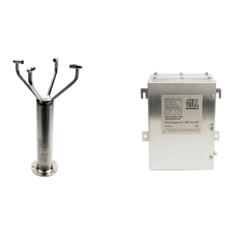
Gill Instruments
Gill Instruments 1360-PK-022 user manual
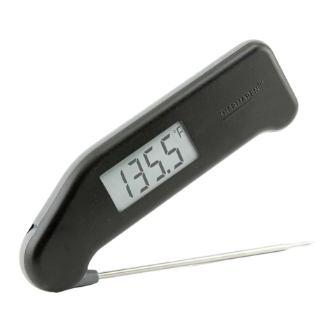
ThermoWorks
ThermoWorks Classic Thermapen operating instructions

Heinzmann
Heinzmann Triton OMD manual
Fastora
Fastora NA-1531 Hardware installation guide
Helwett Packard
Helwett Packard 4339B user guide

Fisher Scientific
Fisher Scientific Fisherbrand accumet AB330 user manual

HP
HP 8163A Series Programming guide
Ecom
Ecom EN2 operating instructions

Emerson
Emerson Rosemount 3410 Series Maintenance and troubleshooting manual
