manuals.online logo
Brands
  1. Home
  2. •
  3. Brands
  4. •
  5. HY Technologies
  6. •
  7. Accessories
  8. •
  9. HY Technologies HYT-F4R4-L User manual

HY Technologies HYT-F4R4-L User manual

User’s Manual
Front and Rear Parking Sensor System
4 Front and 4 Rear In-Bumper Sensors
Wired LED Display with Built-in Audible Alert
For Cars, Mini-VANs, 4X4s, SUVs, and Small Trucks
MODEL HYT-F4R4-L
FCC CE ISO9001
HY Technologies yhttp://parkingsensors.net
Copyright 82007 HY Technologies yMilpitas yCalifornia yUSA All Rights Reserved
- 1 -
Front and Rear Parking Sensor System
4 Front and 4 Rear In-Bumper Sensors
Wired LED Display with Built-in Audible Alert
For Cars, Mini-VANs, 4X4s, SUVs, and Small Trucks
MODEL HYT-F4R4-L
Included in the Box
¾8x Sensors (in-bumper type) with attached
cable and 2-pin mini connector. Cable
Length: Front Sensor = 8.0m (26.2ft); Rear
Sensor = 2.5m (8.2ft)
¾1x LED Display with built-in beeper, On/Off
switch, and 8-pin plug with attached cable
(6m or 19.7ft long)
¾1x Main Control Box
¾1x Double-Sided Self-Adhesive Pad for
affixing main control box to vehicle
¾1x Power Cable for Main Control Box
including three wires (red, yellow, and
black) with a 3-pin connector on one end.
Length: 1.0m (3.3ft)
¾1x Drill Bit - Φ21mm. Note: if drilling
through metal bumpers, you will need a
bi-metal Φ21mm drill bit (not included).
¾8x Plastic Sensor Spacers with wedged
thickness for non-vertical bumpers
¾1x User’s Manual
Features
¾Front and Rear Parking Sensor System to
provide good coverage of both front and
rear end of vehicle
¾4 front and 4 rear in-bumper sensors to
give the look of factory installed system
¾Rear sensors activated while reversing and
front sensors activated while parking
forward and braking
¾Beeping faster when closer to obstacle
¾Wired LED Display with Built-in Audible Alert
(Beeper) with On/Off Switch
¾Seven (7) LED Lights on each side of the
display to indicate both orientation of
obstacles and Safe/Warning/Stop zone.
¾Distance display in feet or meters
¾Designed for cars, SUVs, 4x4s, Mini-VANs,
and small trucks
¾12 Month Warranty
Specifications
¾FCC CE ISO9001 Approved
¾Operating Voltage: DC +10.5 ~ +s16V
¾Detecting Range: 0.3 ~ 2.0m (1.0 ~ 6.6ft).
Displayed as 0.0 when less than 0.3m (1ft)
¾Measuring Error: ±0.1m (or 0.1ft)
¾Sensor Detection Angle: 90°
¾Detection Response Time: 300ms
¾Audible Alert when obstacle within: 0.1 ~
1.5m (0.3 ~ 4.9ft)
¾Ultrasonic Frequency: 40Khz
¾Audible Alert Volume: 60 db
¾Maximum Power Consumption: 4W
¾Current Consumption: 100~300mA
¾Operating Temperature Range: -30 ~ +70°C
¾Dimensions of the LED Display: Width x
Depth x Height = 13.4cm x 3.0cm x 2.8cm
(5.2" x 1.2" x 1.1")
¾Dimensions of the Main Control Box: Width x
Depth x Height = 10.0cm x 7.2cm x 2.5cm
(3.9" x 2.8" x 1.0")
¾Distance display in feet or meters
Note: The specifications are for reference only. They may be changed without prior notice.
Tools Needed
Φ21mm (13/16") drill bit (include), drill, tape measure, chalk or marker, wire stripper, vinyl
electrical tape, cable/wire ties, voltage meter, screw driver set, pliers.
Note: Use a bi-metal 21mm (13/16") drill bit (not included) if drilling through metal bumpers.
- 2 -
How the System Works
The Parking Sensor System determines obstacle distance by measuring the time needed for
the ultrasonic wave emitted by a sensor to reach an obstacle and for the sensor to receive the
ultrasonic wave reflected from the obstacle. Given the speed of the ultrasonic wave, the system
can then calculate and display the distance between the sensor and the obstacle.
To provide good coverage of both front and rear end of vehicle, the system comes with 8
sensors (4 front and 4 rear sensors). To have the look of factory installed system, the 8
sensors are in-bumper type (to be installed in the front and rear bumpers by drilling holes
through the bumpers). Controlled by the +12V from the back up light, the rear sensors are
activated when the vehicle is put in reverse. Controlled by both the +12V from the brake light
and the 0V from the back up light (no +12V applied to the back up lights when parking forward),
the front sensors are activated when the brake is applied and parking forward. It is supplied
with a wired LED display which shows the exact distance from an obstacle in front or rear of the
vehicle. Seven (7) LED Lights (Green/Yellow/Red) on each side of the distance display
indicate both orientation of obstacles and Safe/Warning/Stop zone. The audible alert (beeper)
is built in the display with volume On/Off switch. It beeps faster as vehicle gets closer to
obstacle and sounds continuously when vehicle is within 0.4m (1.3ft) from an obstacle.
- 3 -
Installation and Wiring
IMPORTANT: (a) Read this manual thoroughly before proceeding to installation. You can also
have the system installed by a professional installer such as your local auto mechanic/auto
electrician/car stereo store. (b) Turn off the engine and ACC during installation. (c) Double
check that all wiring is correct before power on the system. (d) During installation, avoid flatting,
perforating, cutting, and extending the wires of sensors to reduce unnecessary signal loss.
1. Installation of the Main Control Box
a) Find a flat and clean surface for the main control box inside the vehicle close to driver's side
taillight assembly. For trucks, you may install it inside the driver's side taillight assembly.
Keep it away from areas of high heat, high humidity, direct water contact, direct sunlight, and
electromagnetic devices.
b) Place the main control box in place temporarily without securing it to the vehicle as you may
need to adjust the location of the main control box while wiring. Note: After completing all
wiring, use the double-sided self-adhesive pad (included) to secure it to the vehicle.
c) Insert the 3-pin plug of the power cable for the main control box into its 3-pin socket labeled
"PWR" on the front side of the main control box (Fig. 3).
2. Wiring the Main Control Box
a) Locate the +12V and the (-) negative wires from the back up light near the taillight assembly.
b) Locate the +12V wire from the brake light near the taillight assembly. If necessary, remove
the taillight assembly to locate them. Strip 1/2" of the wires.
c) Connect the red wire of the power cable to the +12V wire of the back up light (Fig. 3).
d) Connect the black wire of the power cable to the (-) negative wire of the back up light.
e) Connect the yellow wire of the power cable to the +12V wire of the brake light.
f) Wrap all connections with vinyl electrical tape.
3. Installation of the LED Display
a) Find a place for the display on top of the dashboard where the driver can see it easily. Place
the display in place temporarily without securing it to the top of the dashboard. Note: After
completing all wiring, secure it with the included self-adhesive on the bottom of the display.
b) Run the display wire from the top of the dashboard down to the floor, and then to the main
control box in the back of the vehicle (hide the wire under the door or weather trim).
c) Insert the 8-pin connector of the display into its 8-pin socket labeled "DISP" on the front side
of the main control box.
4. Installation of the Sensors
IMPORTANT: (a) To avoid false alert from the system detecting the ground, the sensors should
be mounted between 50cm to 80cm (20" to 32") above the ground and the face of the sensors
need to be vertical or slightly upward angled (Fig.4). (b) Horizontally, the sensors should be
equally spaced if possible or symmetric to the center of the bumper. (c) The outer two sensors
should be mounted about 15cm (5.9") from the corner of the bumper for better corner coverage.
Note: The bumper surface for mounting the sensors should be as flat and vertical as possible.
Use the plastic sensor spacers with wedged thickness (included) if the surface of the
bumpers is non-vertical.
a) Start with the front sensors, and then the rear sensors. Refer to Fig. 1 and 2 for
mounting height and position of the front and rear sensors.
b) Work under the front and rear bumpers to check the internal structure of them before
marking the positions for drilling holes. If the view is blocked, you may need to remove the
bumpers.
c) With chalk or marker, mark the position of sensors on the bumpers. Make sure that the
sensors can be pushed all the way in and that you can feed the wires through.
d) Drill the holes through the bumpers at the marks with the Φ21mm drill bit included. Note: if
drilling through metal bumper, you will need a bi-metal Φ21mm drill bit (not included).
e) If necessary, smooth the sharp edge of the holes with a polishing head or small round file.
Fig. 3 Main Control Box, Display, Sensors, and Wiring
L2
H
L1 L3 L4 L1
Fig.1 Mounting Height and Position of 4 Rear Sensors
H = 50 ~ 80cm (20” ~ 32”)
L1 = 6 ~ 15cm (2” ~ 6”)
L2 = L3 = L4 or L2 = L4 = 0.3L, L3 = 0.4L
Ground
L
Ground
50 ~ 80cm (20”~ 32”)
Sensor Center Line
Parallel to Ground
Sensor
Sensor Mounting Height
Fig.4 Mounting Height and Angle of Sensor
D
C
BA
L5 L8 L7 L6 L5
H
Fig. 2 Mounting Height and Position of 4 Front Sensors
H = 50 ~ 80cm (20” ~ 32”)
L5 = 6 ~ 15cm (2” ~ 6”)
L6 = L7 = L8 or L6 = L8 = 0.3L, L7 = 0.4L
Ground
L
E
F
GH
Back Up
Light
Red (+) 12V
Gnd
Main Control Box
A B C D
PWR
Beeper On/Off Switch
on Back of Display
R
L8.8
LED Display
Power Plug
Sensor
Plugs
EFGH
DISP
D
C
B
A
Rear Sensors
HG
F
E
Front Sensors
Brake
Light
Yellow (+) 12V
Black ( - )
Display Plug
Main Control Box
- 4 -
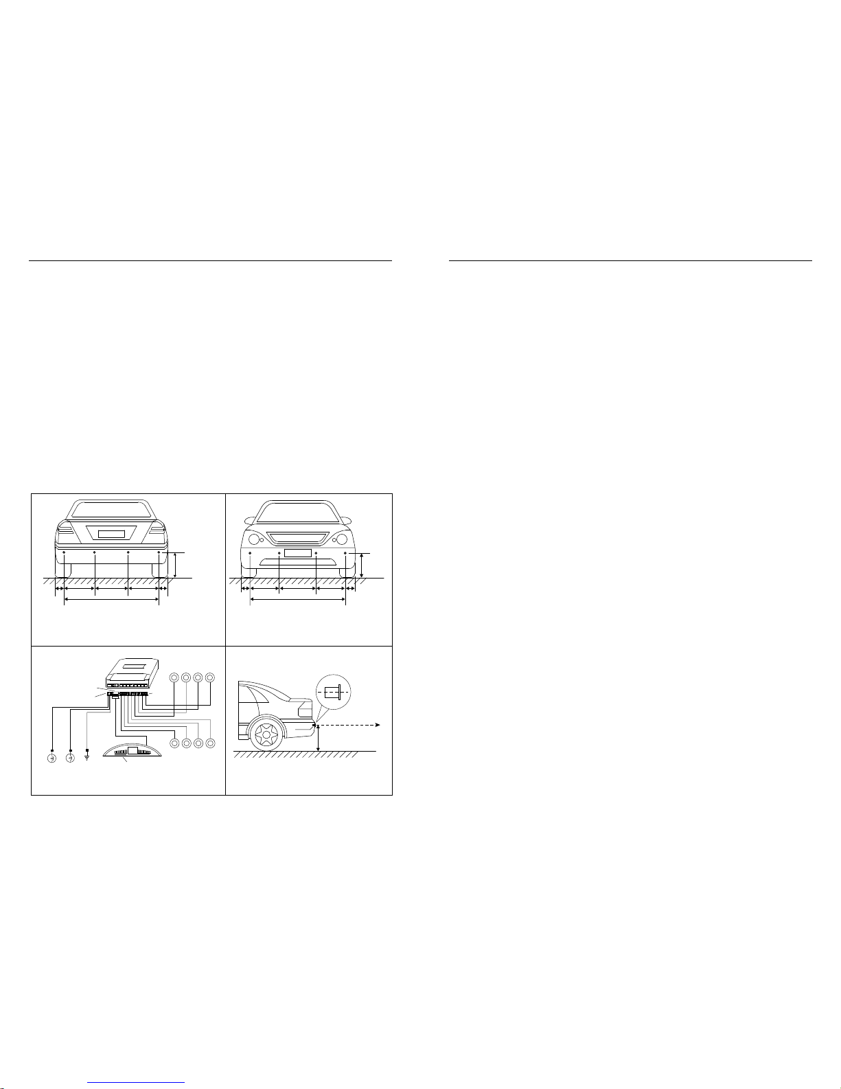
f) Run the sensor wires into the holes drilled. Push the sensors into the holes. When pushing
the sensors only apply pressure at the edges, not on the middle of the sensor to avoid
damage to the sensor element. The sensors are tapered for a snug fit.
g) Adjust the sensors for non-vertical bumper surface by using/rotating the plastic sensor
spacers with wedged thickness (included).
h) For front sensors, run the sensor wires from the front bumper into the inside of the vehicle
through the existing wiring holes or rubber grommet in the fire wall, and then to the main
control box in the back of the vehicle (hide the wire under the door or weather trim).
i) For rear sensors, run the sensor wires from the rear bumper into the trunk or inside of the
vehicle through the existing small vent or rubber grommet in the rear of the trunk or vehicle,
and to the main control box. Note: Do not cut the excess sensor wires to avoid signal loss.
j) Attach sensor wires to the vehicle body with cable/wire ties so that they will not get in the
way of any moving parts and there are no loose wires hanging down.
k) Plug all sensors into their corresponding sockets at the main control box.
Testing Your New Parking Sensor System
For the rear sensors, back your vehicle slowly (about 3 miles per hour) to approximately 1.5m
(4.9 feet) from a flat vertical surface such as a wall. Continue to back up slowly and check the
performance against Chart 1. For the front sensors, do the same test while parking forward
slowly with braking.
Note: have somebody watch the vehicle while you are doing the test.
Using the Display
The display has a built-in beeper (audible alert) with On/Off Switch. There are seven (7) LED
Lights (2 Green, 3 Yellow, 2 Red) on each side of the two-digit distance display (Fig. 3). The
color LED lights indicate both orientation of obstacle and Safe/Warning/Stop zone (Chart. 1).
Chart 1. Orientation of Obstacle, Distance Display, and Beeping (Audible Alert)
Viewing from the Front of the Display
Obstacle
Distance LEDs on the Left Side
of the Display
Responding to Rear Sensor A,B
or Front Sensor E,F
Beeping Digital
Distance
Display
LEDs on the Right Side
of the Display
Responding to Rear Sensor C,D
or Front Sensor G,H
Safe Zone
(> 2.0m) No LEDs on No -.- No LEDs on
Safe Zone
(2.0~1.5m) 1 Green on Starting to
beep at 1.5m
Actual
distance
1 Green on
Warning
Zone
(1.5~1.0m)
1 - 3 Green on Fast
Actual
distance
1 - 3 Green on
Warning
Zone
(1.0~0.7m)
3 Green/1 -2 Yellow on Faster
Actual
distance
1 -2 Yellow/3 Green on
Stop Zone
(0.7~0.3m) 3 Green/2 Yellow/1 - 2 Red on Fastest
Actual
distance
1 - 2 Red/2 Yellow/3 Green on
Stop Zone
(0.3~0.0m) 3 Green/2 Yellow/2 Red on Continuously 0.3 or 0.0 2 Red/2 Yellow/3 Green on
- 5 -
Warning
zTo avoid collision with obstacle because of the inertia of vehicle while backing up/parking,
keep your vehicle speed at about 3 miles per hour and stop the vehicle immediately once
you hear the continuous beeping. This is because even if you have applied brake, your
vehicle will still go for some distance (inertia) before it comes to a complete stop.
zBecause the back up parking system detects obstacle by emitting ultrasonic wave and
receiving reflected ultrasonic wave from obstacle, the system may fail to give both visual and
audible alert if an obstacle has smooth ball-shaped or sloped surfaces as such surfaces may
not reflect ultrasonic wave back to the sensors. Drivers in these situations should pay more
attention while parking their vehicles.
zIn heavy falling rain or snow, the system may give alert as falling rain or snow may be
detected as obstacles. Keep surface of sensors clean of snow, mud, dirt, and other debris.
Troubleshooting
Problem Cause Solution
Display doesn't
light up when
reversing or
parking forward
with braking
Display not plugged in.
No power to the main control box.
Faulty display.
Check display connection.
Check main control box power connection.
Replace the display.
Contact Technical Support for help.
Display light up
but system is not
detecting any
obstacle
Sensors not connected.
Faulty display.
Faulty main control box.
Check sensor connections.
Replace the display.
Replace the main control box.
Contact Technical Support for help.
System showing
distance but no
beeping or
system beeping
but no distance
display
Beeper turned off.
Faulty display.
Faulty main control box.
Turn on beeper.
Replace the display.
Replace the Main Control Box.
Contact Technical Support for help.
System is not
detecting any
obstacle in front
System has no +12V from brake light.
Check main control box connection to +12V from
brake light.
System is not
detecting any
obstacle in rear
System has no +12V from back up light.
Check main control box connection to +12V from
back up light.
Wrong LEDs light
up Sensors are plugged into the wrong
sockets at the main control box Install the sensors in the bumper as labeled in
Fig. 1 & 2 and plug sensors as labeled on the
sensor wires into their corresponding sockets at
the main control box (Fig. 3)
Display
constantly shows
0.0 or beeps
continuously
Object within 0.40m is detected.
Faulty sensor(s).
Faulty main control box
Unplug all sensors, and then plug back in one
sensor at a time to find out which sensor is
causing the problem. Adjust angle of the sensor.
Refer to 4. Installation of the Sensors for
details.
Replace the sensors(s).
Replace the main control box.
Contact Technical Support for help.
Display shows a
distance and
beeps even there
is no obstacle
behind or in front
Ground is detected.
Sensors angle is low.
Sensors installed too low (mounting
height below 0.5m)
Unplug all sensors, and then plug back in one
sensor at a time to find out which sensor is
causing the problem. Adjust angle of the sensor.
Refer to 4. Installation of the Sensors for
details.
For more installation related questions and Frequently Asked Questions (FAQs) with
answers, and product photos, visit our Web site at http://parkingsensors.net
- 6 -
IMPORTANT
The Parking Sensor Systems sold and distributed by HY Technologies are only devices used to
assist a driver while parking. They should not be considered as a substitute for driver
responsibility when operating a vehicle. No warranty as to operational efficiency is granted. We
don't guarantee or assume liability for collisions or damages that take place when parking your
vehicle with the use of the Parking Sensor System. We will not be liable for any claims, actions,
suit proceedings, costs, expenses, damages or liabilities arising out of the use of this product.
By purchasing, installing and using such a Parking Sensor System, customers agree to take full
responsibility of use of such System.
Returns and Warranty
We offer 12 month product warranty. This warranty excludes defects or damage due to misuse,
abuse or neglect.
Returns/exchanges can be made within 15 days of your receipt of your order.
Note: You are responsible for the shipping cost to mail the defective parts, returns, exchanges,
and items for Warranty back to us and for us to ship them to you.
Items for return must be in new, unused, re-sellable condition in their original condition,
including the original packaging, manufacturer's containers, documentation, warranty cards,
manuals, and all accessories.
Unopened returns are subject to a 15% re-stocking fee. Opened returns are subject to a 25%
re-packing and re-stocking fee. Returns which are damaged or have parts missing may be
subject to a greater re-stocking fee or returned to customer. Shipping to customer is not
refundable.
Returns are not acceptable if the packaging is not in its original condition or the item has been
used or installed. International orders are not returnable.
If a domestic or international shipment is refused by the customer or customs and returned back
to us, a 15% restocking fee will apply less the shipping cost to the customer. It is the customer's
responsibility to make all arrangements with us for refused shipments.
For your return to be processed, you need to contact our Customer Service by visiting our Web
site (then click on the Contact Us link) to get your Return Merchandise Authorization Number
(RMA#).
Customer Service and Technical Support
For customer service and technical support, visit our Web site as listed below, then click on the
link Contact Us.
Spare and Replacement Parts
To order spare and replacement parts for your system, visit our Web site as listed below, then
click on the link Replacement Parts.
HY Technologies yhttp://parkingsensors.net
Copyright 82007 HY Technologies yMilpitas yCalifornia yUSA All Rights Reserved
- 7 -
HY Technologies yhttp://parkingsensors.net
Copyright 82007 HY Technologies yMilpitas yCalifornia yUSA All Rights Reserved
Made In China

Popular Accessories manuals by other brands

Panasonic AW-PB304 operating instructions

Panasonic

Panasonic AW-PB304 operating instructions

Allied Telesis AT-BMGMT Quick install guide

Allied Telesis

Allied Telesis AT-BMGMT Quick install guide

Campbell SnowVUE 10 product manual

Campbell

Campbell SnowVUE 10 product manual

Celestron C10-NGT Communication protocol

Celestron

Celestron C10-NGT Communication protocol

IntelliSense DT-7225 installaiton instructions

IntelliSense

IntelliSense DT-7225 installaiton instructions

LEEC SL2 operating instructions

LEEC

LEEC SL2 operating instructions

inventum HN1312V instruction manual

inventum

inventum HN1312V instruction manual

Hunter MINI-CLIK installation instructions

Hunter

Hunter MINI-CLIK installation instructions

Stack ST994 installation instructions

Stack

Stack ST994 installation instructions

Banner L-GAGE LH Series instruction manual

Banner

Banner L-GAGE LH Series instruction manual

NAPCO PIR600 installation instructions

NAPCO

NAPCO PIR600 installation instructions

Waycon MH60 Series installation guide

Waycon

Waycon MH60 Series installation guide

BASETech 1574789 operating instructions

BASETech

BASETech 1574789 operating instructions

Omron E3S-G datasheet

Omron

Omron E3S-G datasheet

Arrow Storage Products CPH101507 Owner's manual & assembly guide

Arrow Storage Products

Arrow Storage Products CPH101507 Owner's manual & assembly guide

Vermont Castings SDFBVT installation instructions

Vermont Castings

Vermont Castings SDFBVT installation instructions

Razor RipSurf owner's manual

Razor

Razor RipSurf owner's manual

Druck UNIK5600 manual

Druck

Druck UNIK5600 manual

manuals.online logo
manuals.online logoBrands
  • About & Mission
  • Contact us
  • Privacy Policy
  • Terms and Conditions

Copyright 2025 Manuals.Online. All Rights Reserved.