Sensoterra Single Depth User manual

MinFarm BIA AB March 2021 Version 1.3
1
How to use Sensoterra sensors over the Inmarsat IsatData Pro satellite network with
the MinFarm MF-400 IoT Satellite Bridge
Version 1.3 March 2021

MinFarm BIA AB March 2021 Version 1.3
2
Copyright © 2021 MinFarm BIA AB
All rights reserved. This publication and its contents are proprietary to MinFarm BIA AB. No part of this
publication may be reproduced in any form or by any means without the written permission of MinFarm BIA
AB. MinFarm BIA AB has made every effort to ensure the correctness and completeness of the material in
this document. MinFarm BIA AB shall not be liable for errors contained herein. The information in this
document is subject to change without notice. MinFarm BIA AB makes no warranty of any kind with regard
to this material, including, but not limited to, the implied warranties of merchantability and fitness for a
particular purpose.
Trademarks
All trademarks are the property of their respective owners.
Permissions
Permissions have been obtained from CPN Satellite Services GmbH for inclusion of text (ref Installation
Manual MF-400 IoT Satellite Bridge, Version 1.2 – Date: 07 Jan 2021) and Sensoterra International B.V. for
use of images.

MinFarm BIA AB March 2021 Version 1.3
3
Table of Contents
Section 1 - Introduction 4
Section 2 - Components Required 9
2.1 - Device(s) with sensor(s) attached 9
2.2 - MF-400 Gateway 11
2.2.1 - MF-400 Technical Overview 12
2.2.2 - MF-400 Contents 12
2.2.3 - Required Tools for Installation 12
2.2.4 - Safety Instructions 13
2.2.5 - MF-400 Installation 14
2.3 - Inmarsat IsatData Pro Satellite Terminal 30
Section 3 - Software Staging Preparation Required Before Field Installation 31
3.1 - Sensoterra application software 31
3.2 - MinFarm Bridge Server 33
Section 4 - Total System Test before Field Installation 33
Section 5 - Field Installation 34
Section 6 - Terminology and Abbreviations 35
Section 7 - Contact Details 36
MinFarm BIA AB March 2021 Version 1.3
4
Section 1
Introduction
Are you a farmer with a medium or large sized land area in a location of little or no cellular data coverage
and electrical power? Would you like to have access to your soil moisture levels on an easy to use interface
on your mobile phone or laptop? Remote monitoring of your farm and lands 24 hours, from anywhere.
All data is displayed on your mobile phone or laptop.

MinFarm BIA AB March 2021 Version 1.3
5
MinFarm BIA AB March 2021 Version 1.3
6
So what do you need? Have a look at Schematic 1.
Schematic 1

MinFarm BIA AB March 2021 Version 1.3
7
You will need:
1. Sensoterra Single Depth soil moisture sensor
2. MF-400 Gateway
3. Inmarsat IsatData Pro (IDP) Satellite Terminal
4. Sensoterra application software on your mobile phone or laptop
The technical part in simple terms! How does it all work? There are two main networks involved. One is
called LoRaWAN™, and the other is the Inmarsat satellite network.
https://lora-alliance.org
The LoRaWAN™ (‘long range wide area network’) is a low power wireless network that allows you connect
wireless battery operated devices to a gateway that can be several kilometres away. Through this gateway,
the devices can then connect to the Internet. So it is low power, has a good range, and is wireless - these
are the important facts to remember about this network.
https://www.inmarsat.com
The Inmarsat satellite network provides a global, reliable and trusted method of accessing the Internet
using low-powered, portable satellite terminals.
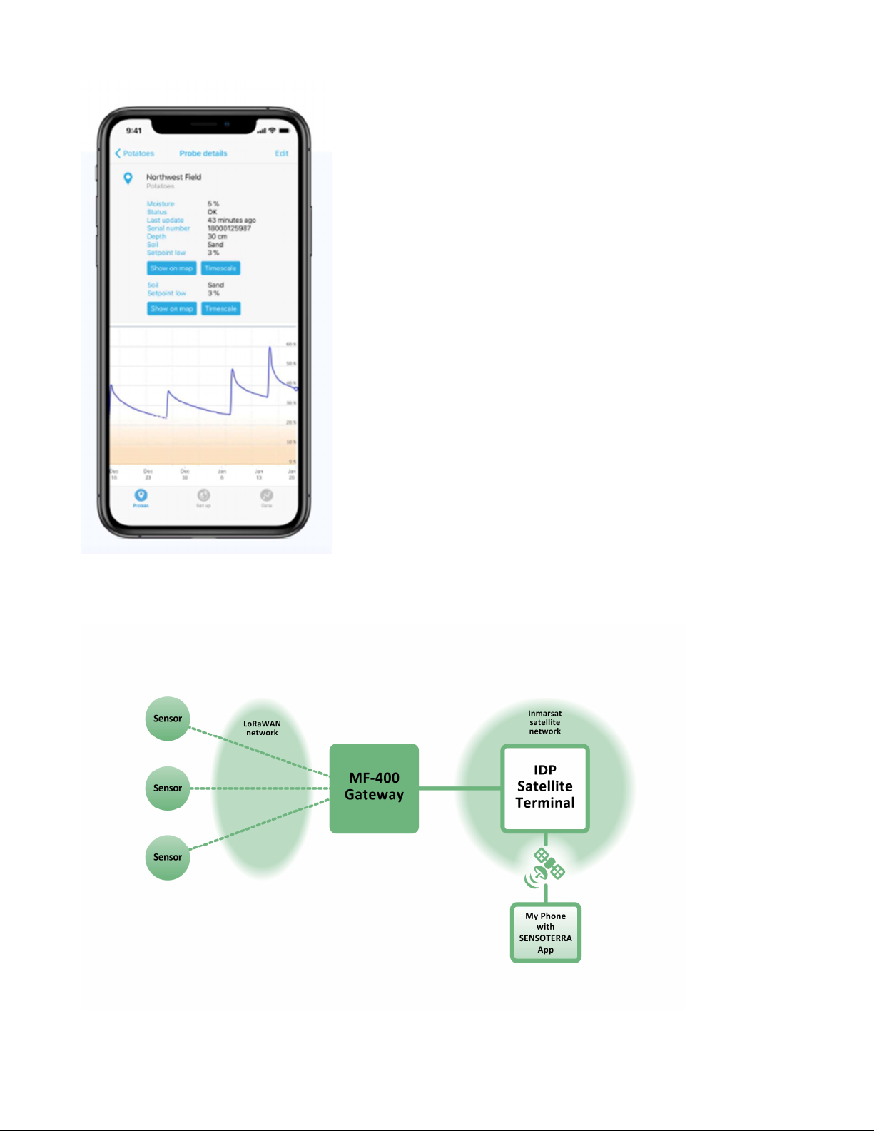
Your Sensoterra single depth sensor sits out in a remote area of your land. Every hour your sensor sends
information to the MF-400 Gateway. This is sent over the LoRaWAN network that we talked about. It passes
the information to the IDP satellite terminal, up to the satellite in the sky, back down to a satellite receiving
station, called the IDP gateway, which then passes it on to the MinFarm Bridge Server, and then on to your
mobile phone where you can view it using the Sensoterra application software. This flow of information can
be seen in Schematic 2, just slightly more detailed than Schematic 1.

MinFarm BIA AB March 2021 Version 1.3
8
Schematic 2

MinFarm BIA AB March 2021 Version 1.3
9
Section 2
Components Required
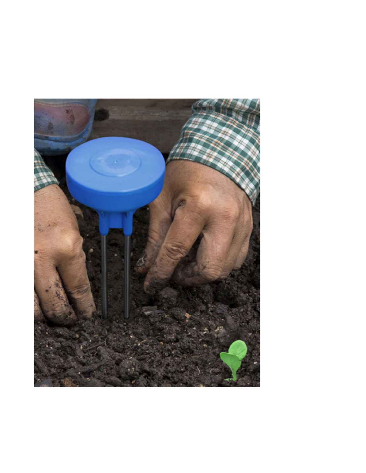
2.1
Single Depth Sensor
The picture below shows a Sensoterra single depth sensor which measures soil moisture levels. Sensoterra
also produce a multi depth device which has 6 different sensors attached, but for the purpose of this paper
we will talk about the single depth sensor. The MF-400 IoT Satellite solution will work with both sensors in a
similar way. You should contact Sensoterra to discuss what sensor best suits your requirements.

MinFarm BIA AB March 2021 Version 1.3
10
Device Installation:
Refer to the Sensoterra Installation Guide
https://www.sensoterra.com/uploads/documents/Installation/SD_Installation_guide_1.0.pdf for particular
installation and set-up instructions for your single depth sensor.
MinFarm BIA AB March 2021 Version 1.3
11
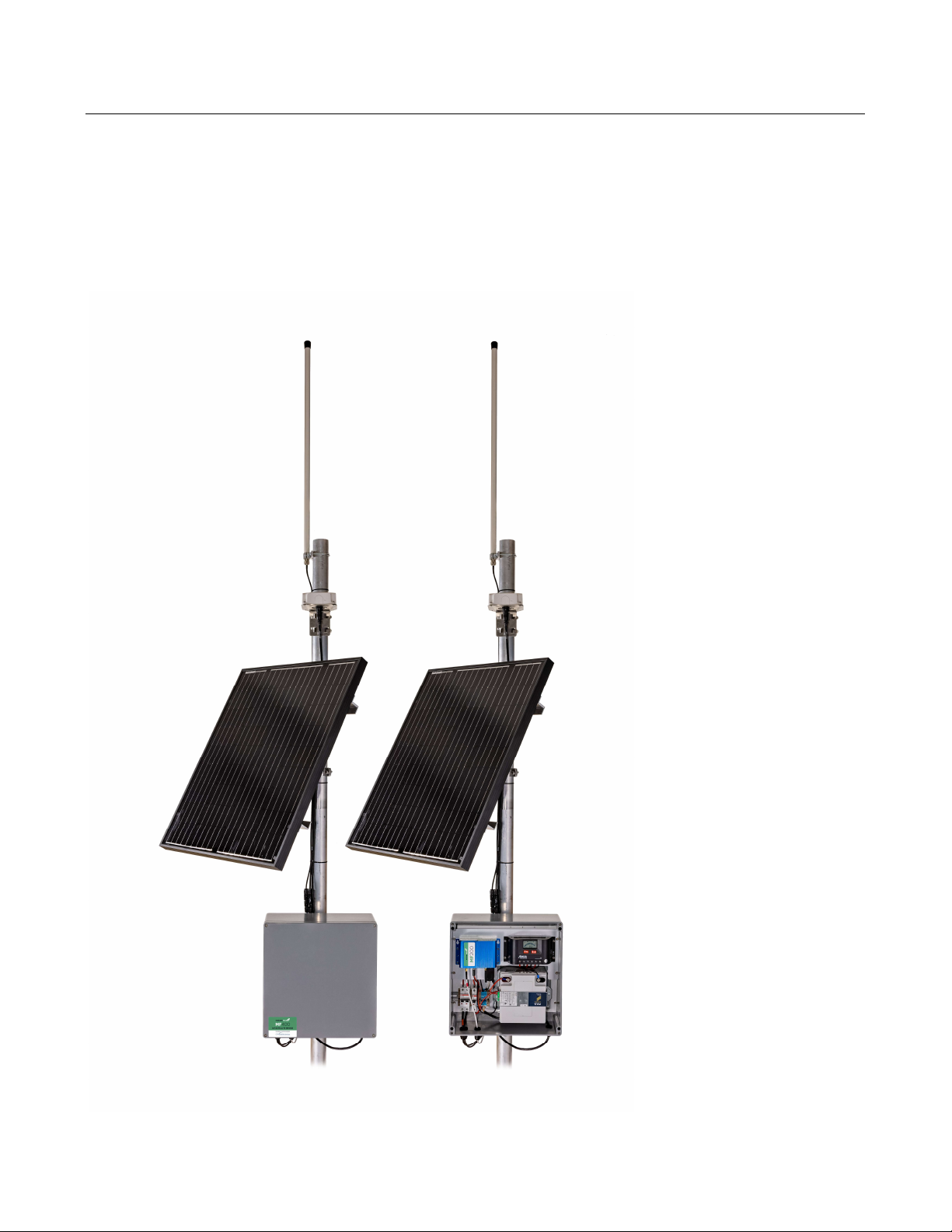
2.2
MF-400 Gateway
The MF-400 can be seen in the pictures below. You will need to contact CPN Satellite Services to purchase
a gateway unit.

MinFarm BIA AB March 2021 Version 1.3
12
2.2.1
MF-400 Technical Overview
The MF-400 Gateway provides network server connectivity for 100 remote LoRaWAN™ sensors via Inmarsat
IsatData Pro (IDP) satellite terminals and can operate continuously from a single 80W solar panel.
The MF-400 runs an optimized protocol to ensure that airtime satellite costs per sensor are kept to a minimum.
This makes the MF-400 a standalone, low power, low-cost solution for adding satellite connectivity to your
existing COTS LoRaWAN™ sensor devices.
The MF-400 Gateway supports LoRaWAN™ version 1.0.2, and is compatible with a very wide range of
commercial off the shelf (COTS) LoRaWAN™ sensors.
Both the communication device and the solar charger are installed in IP67 rated CPN enclosures for harsh
environments.
2.2.2
MF-400 Contents
1 x IP67 Enclosure (400 x 405 x 160mm)
1 x 12V battery
1 x STECA PR 1010 Solar Charger
1 x 80W 12V Solar Panel (670 x 770 x 30mm)
1 x LoRa Omnidirectional Antenna (8dBi, 0.8m)
1 x Enclosure Pole Mount
1 x LoRa Antenna Pole Mount
1 x IDP Satellite Terminal Power & Data Cable (5m)
1 x Solar Panel to Enclosure Cable
1 x LoRa Antenna Cable (5m)
2.2.3
Required Tools for Installation
Phillips screwdriver - PH3
Enclosure lid
Phillips screwdriver - PH2
Battery

MinFarm BIA AB March 2021 Version 1.3
13
Slotted screwdriver - 0.6x3.5mm
Terminal blocks
Wrench - #8
Pole mount Enclosure & IDP terminal
Wrench - #10
LoRaWAN antenna
Wrench - #13
Solar panel
Zip ties
Wire cutter
2.2.4
Safety Instructions
An external fuse or circuit breaker (max. 20A) must be provided in the onsite installation as an interrupt
facility for the enclosure system – Only applicable to AC powered systems!. WARNING Risk of electrical
shock, fire, personal injury, or death.
Do not use a power supply without proper grounding (Protective Earth). Use the terminal on the
input block for earth connection. Make sure that protective earth is connected according to all local
and national codes and regulations!
Turn the power off before working on the device. Protect against inadvertent re-powering.
Make sure that the wiring is correct by following all local and national codes.
Do not modify or repair the unit.
Do not open the electronic units, e.g. power supply, as high voltages are present inside.
Use caution to prevent any foreign objects from entering the housing.
Do not use in wet locations or in areas where moisture or condensation can be expected while the
cover is not mounted.
Do not touch during power-on, and immediately after power-off. The hot surface may cause burns.

MinFarm BIA AB March 2021 Version 1.3
14
2.2.5
MF-400 Installation
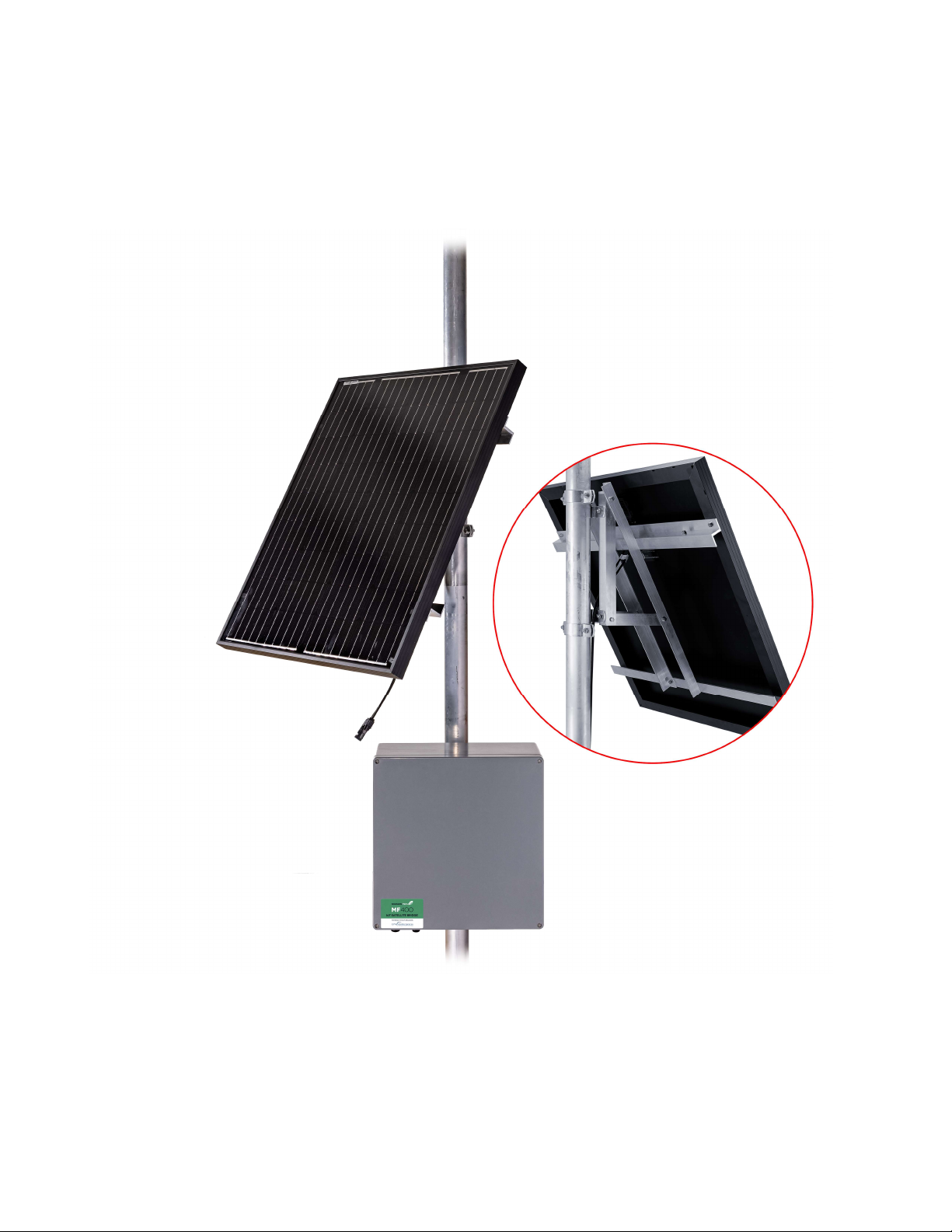
Step 1 - Mount the enclosure to the pole.
Mount the enclosure to the pole by using the pole mount located at the backside of the enclosure.
MinFarm BIA AB March 2021 Version 1.3
15
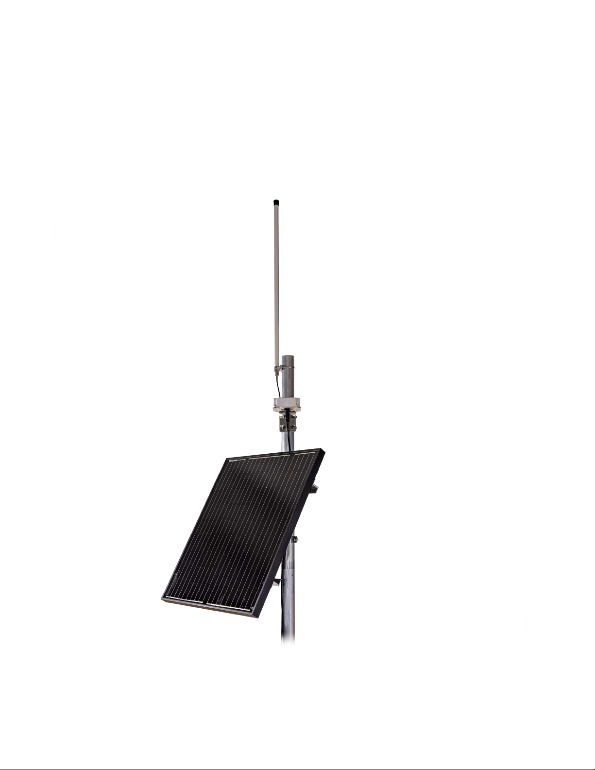
Step 2 - Mount the solar panel to the pole.
Mount the solar panel to the pole by using the pole mount located on the backside of the solar panel.

MinFarm BIA AB March 2021 Version 1.3
16
Step 3 - Mount the antenna to the pole.
Plug the antenna cable into the antenna and use its pole mount to secure it onto the top of the pole.
Please make sure that your installation matches antenna cable requirements!
MinFarm BIA AB March 2021 Version 1.3
17
Step 4 - Mount the IDP Terminal to the pole.
Plug the IDP cable into the IDP terminal and use its pole mount to secure it onto the pole. We recommend
using zip ties to fix the cables to the pole.
Please make sure that your installation matches cable requirements!
MinFarm BIA AB March 2021 Version 1.3
18
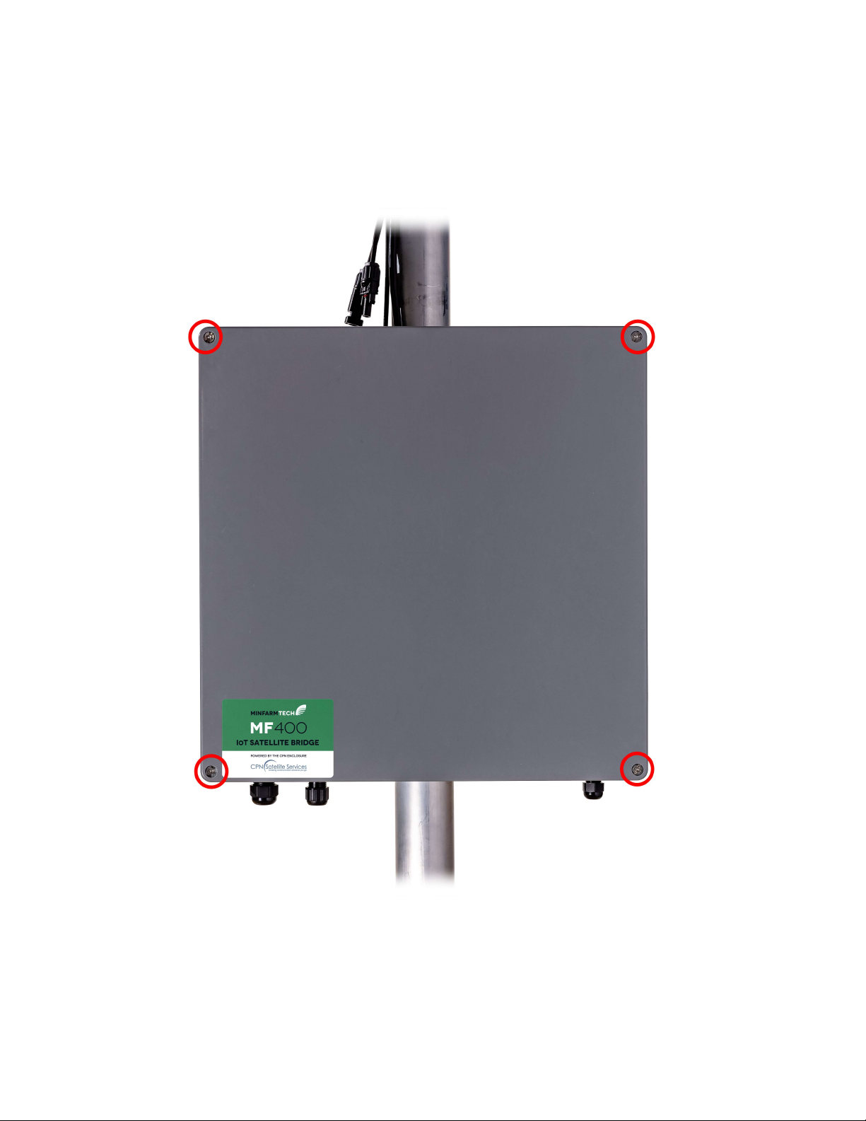
Step 5 - Open the enclosure.
Loosen the 4 marked screws of the cover and remove it from the enclosure.
MinFarm BIA AB March 2021 Version 1.3
19
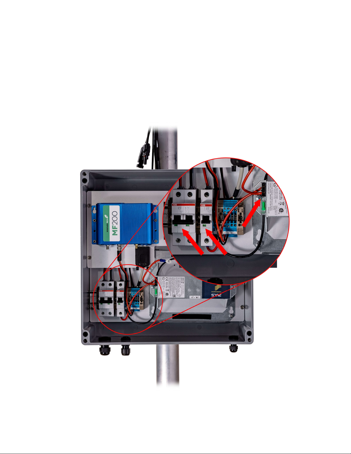
Step 6 - Ensure all circuit breakers are switched off / not plugged in.
Make sure all circuit breakers are switched off and pointing down. Ensure that there is no fuse plugged into
the battery mount.
Red = ON
Green = OFF
MinFarm BIA AB March 2021 Version 1.3
20
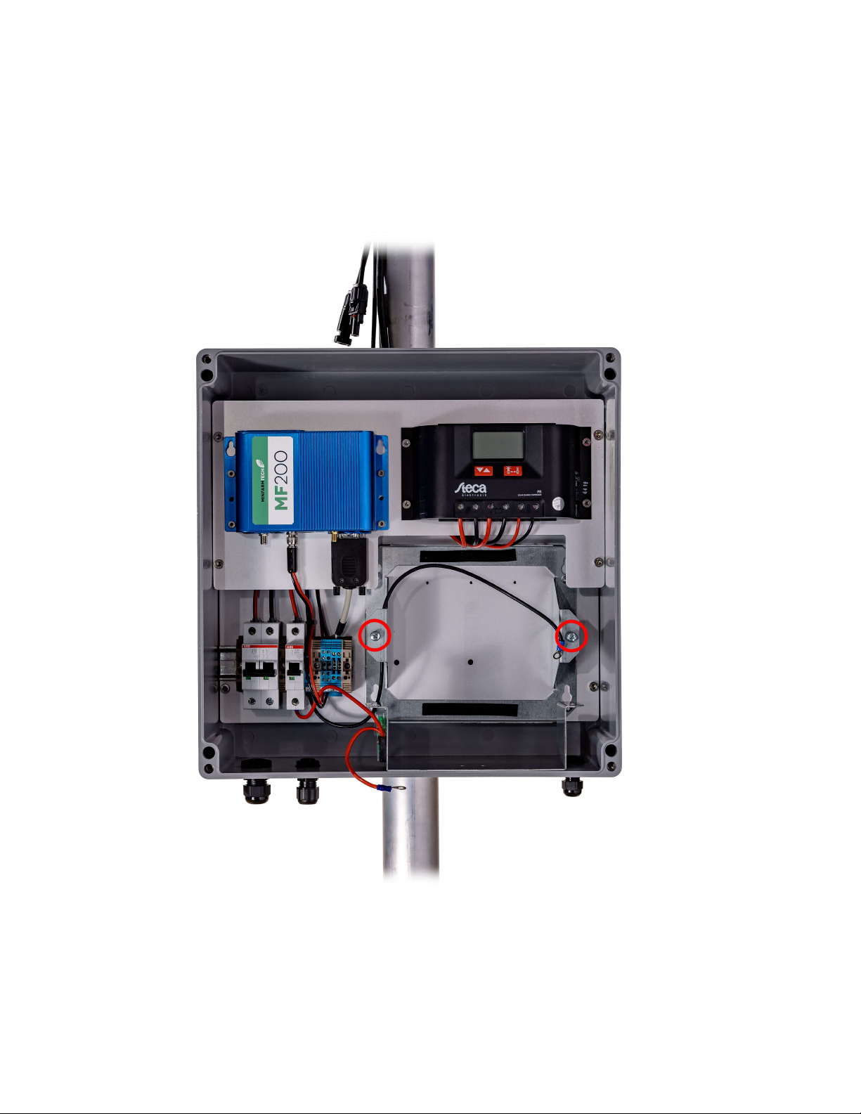
Step 7 - Remove the top of the battery mount.
Remove the top cover of the battery mount by loosening the 2 marked screws.
Make sure that all circuit breakers are switched to OFF during installation!
Table of contents
Popular Farm Equipment manuals by other brands

Agri-Fab
Agri-Fab 45-0390 quick start guide

MASSEY FERGUSON
MASSEY FERGUSON MF 9100 VE Operator's manual

HARVEST
HARVEST T1052 Operator's manual

Redexim
Redexim Easy Spread 1500 Operator and parts manual

Poettinger
Poettinger AEROSEM F 5000 Mounting instructions

Rabe
Rabe KORMORAN PL V 180 operating instructions

Suevia
Suevia 130.6150 Mounting instructions

Farmet
Farmet Triolent TX 300 N operating manual

McHale
McHale Fusion 2 Operator's instruction manual

Spearhead
Spearhead Multicut 300 Handbook and Parts manual

SAKALAK
SAKALAK SK-PHM BERAT OPERATOR'S MANUAL AND SPARE PARTS

Ferrari Costruzioni Meccaniche
Ferrari Costruzioni Meccaniche FUTURA NORMAL Operating and service manual


