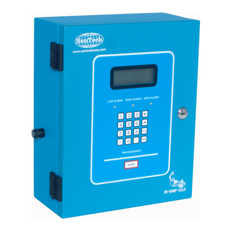
SenTech IR-SNIF-MCD Series User manual

SenTech Corporation
5745 Progress Road
Indianapolis, Indiana 46241
888/248-1988
FAX 317/248-2014
INSTALLATION AND OPERATION MANUAL
ENVIRONMENTAL SYSTEM IR-SNIF-MCD
MODELS MCD-1, 4, 8 & 16

ii
APPLICABILITY
Information presented in this manual can be generally applied to all IR-SNIF-MCD refrigerant
monitors. Specific details of programming and operator interface apply to software version
5327K and later versions. To determine the version of an IR-SNIF-MCD, press the “*” key.
This will display momentary screens that provide contact information for SenTech Corporation,
the software version and any options enabled in the monitor. If your monitor has a version that
is older (smaller version number such as 2143), a version specific appendix A, Programming
and Operator Interface, is available. It can be downloaded from the SenTech Corporation
website, www.sentechcorp.com, or directly from SenTech Corporation at 888-248-1988.

iii
Contents
SAFETY PRECAUTIONS and WARNINGS............................................................................ 1
Models MCD-1, 4, 8 & 16 Specifications .................................................................................. 2
INTRODUCTION and OVERVIEW ......................................................................................... 3
Functional Description............................................................................................................ 3
Sensitivity to Refrigerants....................................................................................................... 8
Factory Calibration ................................................................................................................. 8
PPM vs. Leak Rate.................................................................................................................. 8
SYSTEM Block Diagram ........................................................................................................... 9
INSTALLATION ..................................................................................................................... 12
Unpack and Inspect Material ................................................................................................ 12
Identify Location for Monitor, Sample Points and Alarms .................................................. 12
Electrical Power Connection................................................................................................. 13
Electrical Alarm Connections............................................................................................... 14
Other External Connections.................................................................................................. 15
STARTUP and PROGRAMMING........................................................................................... 18
Apply Power ......................................................................................................................... 18
Initial Screens........................................................................................................................ 18
Normal Operation ................................................................................................................. 19
Initial Programming.............................................................................................................. 19
FINAL TESTS .......................................................................................................................... 25
Monitor Sequencing.............................................................................................................. 25
Integration with External Devices ........................................................................................ 25
Response to Refrigerant........................................................................................................ 26
End-to-End System Test ....................................................................................................... 27
Documentation...................................................................................................................... 28
PREVENTIVE MAINTENANCE & REPAIR ........................................................................ 29
Preventive Maintenance........................................................................................................ 29
Commonly Ordered Parts ..................................................................................................... 29
Monitor Repair...................................................................................................................... 29
APPENDIX A: Programming and Operator Interface.............................................................. 30
Summary ............................................................................................................................... 30
Start-up Screens .................................................................................................................... 30
Operational Screens .............................................................................................................. 30
Menu Screens........................................................................................................................ 32
APPENDIX B: SenTech Room Volume Considerations ......................................................... 40
APPENDIX C: Parts List and Wire List................................................................................... 44
TROUBLESHOOTING GUIDE .............................................................................................. 47
SenTech Manufacturer's Limited Warranty.............................................................................. 50

1
SAFETY PRECAUTIONS and WARNINGS
The following general safety precautions and warnings must be observed during all phases of
installation, operation, service and repair of equipment. Failure to comply with these
precautions, given here and elsewhere in the manual violates safety standards of design,
manufacture, and intended use. SenTech Corporation assumes no liability for the customer’s
failure to comply with these requirements.
Definitions of safety symbols used on equipment and in manuals.
AC Voltage Terminal: Indicates areas of equipment where AC line voltages are used
and present a potential risk of electrocution. Areas using line voltages should not be
accessed during operation.
AC-to-DC Power Supply: Indicates AC line voltages are used and present on portions
of the power supply, including the heat sinks. A potential risk of electrocution exists.
Areas using line voltages should not be accessed during operation.
Protective Grounding Terminal: The protective ground is to prevent electric shock in
case of an electrical fault. This symbol indicates that the terminal must be connected to
earth ground before operation of the equipment.
Caution: This sign calls attention to a procedure or practice which if not adhered to
could result in damage or destruction to a part of the product.
Other information and precautions:
Input Power: Power should be supplied through a two-pole circuit breaker located in a
reasonable proximity to the equipment. Ensure that the voltages are correct and an
appropriate ground connection is provided.
Do Not Open the Monitor with Power Applied: Line voltages exist on the terminal board
inside the monitor and on the power supply inside (including the heat sinks). The door to the
monitor and the power supply itself are marked with AC Voltage shock hazard warning labels.
Remove power prior to opening the door.
Installation, Maintenance and Repair: These functions should only be done by qualified
personnel following the instructions outlines in this manual. This is Installation Category III
equipment.
Pollution Degree: This equipment is designed for a Pollution Degree of 1.
Cleaning: This equipment should be cleaned by wiping with a soft clean cloth.
Intended Purpose: This equipment is designed to be used as a continuous refrigerant
monitor. It should not be used for any other purpose.

2
Models MCD-1, 4, 8 & 16 Specifications
Size: 16.5” x 15” x 6.75” (42cm x 38.1cm x 17cm)
Weight: Model MCD-1 - 30.4 lbs. (13.8 kg)
Model MCD-4 - 31.4 lbs. (14.2 kg)
Model MCD-8 - 33.8 lbs. (15.3 kg)
Model MCD-16 - 36.0 lbs. (16.3 kg)
Power: 120 or 240 Volts AC 50/60hz (41 Watts)
Temperature: 32 deg F – 125 deg F (0 deg C – 50 deg C)
Humidity: 0 – 95 % non-condensing
Atmospheric
Pressure:
75-106 Kpa
Equipment rated for indoor use only
Range: 0 – 1000 ppm Standard
Tube Length: 0 – 250 ft (0 – 76 m)
Sample
Areas:
Model MCD-1 - 1 Area
Model MCD-4 - 4 Areas
Model MCD-8 - 8 Areas
Model MCD-16 - 16 Areas
Trip Point: Low Alarm 0 – 1000 ppm
Main Alarm 0 – 1000 ppm
High Alarm 0 – 1000 ppm
Horn Alarm Programmable to Low, Main or High
Leak Wait: Varies from seven (7) seconds to three (3) minutes depending on
refrigerant concentration
Alarm
Output:
Low, Main, High and Horn alarm relays, each with four (4) form C
contacts rated 5 amps maximum
Analog
Output:
0 – 10 volt proportional to 0 – 1000 ppm
4-20 mA (optional)
Computer
Interface:
RS-485 (optional)

3
INTRODUCTION and OVERVIEW
The SenTech Environmental System IR-SNIF-MCD refrigerant monitor provides an early
warning of developing refrigerant leaks. The unit samples ambient air and measures the
amount of halogen based refrigerant gas in the air sample. When the proportion of refrigerant
present exceeds a trip point, the system goes into alarm mode. Should the system assess the
presence of refrigerant as a leak, using SenTech’s “LEAK WAIT” algorithm, the user is notified.
By discovering a leak shortly after it starts, the potential loss can be reduced to ounces of
refrigerant, saving money and helping protect the environment.
Functional Description
The refrigerant monitor is composed of four major functional blocks: Pneumatics, Infrared
Bench, Control Electronics and Power Supply. Refer to figure 1 for an overall block diagram.
The pneumatics pulls sample air or reference air from up to 250 feet and pumps the air
through a filter, to a pressure sensor, through the infrared bench and out the exhaust port of
the monitor. The infrared bench provides an infrared source and measures the presence of
refrigerant based on measured changes in the infrared light. The control electronics switches
the pneumatic valves from one area to reference air and on to the next area, measures and
stores the information from the infrared bench, provides a human machine interface for
programming and provides analog, digital and relay outputs to interface with building systems
and alarms.
IR Bench
Press. Switch
Diaphragm Pump
Relays
Terminal Board
Control Electronics
LOW MAIN HIGH
Valves
Area 1
Reference Air
Power Supply
Valve Driver Board
TB3
Terminal Board
TB6 (opt.)
HORN
Area 5
Area 6
Area 2
Area 4
Area 7
Area 8
Area 3
Exhaust
Figure 1 Overall Block Diagram

4
Pneumatics: Refer to the figure 2 for pneumatics block diagram. Tubing from the areas to be
monitored and from a reference air source (either fresh, outside air, or interior conditioned air
that is free of refrigerants) is connected to the valve manifold. The MCD1 has a single sample
valve and a reference valve, for a total of two valves. The MCD4 has four sample valves, the
MCD8 has eight and the MCD16 has 16, for a total of five, nine and seventeen valves
respectively. The electronics alternates between energizing the Sample air and the Auto zero
air valves. Following an Auto zero cycle, the pneumatics will be switched to the next sample
valve in order. The diaphragm pump draws air from the selected inlet and feeds the air
through a five micron filter, through an orifice restrictor, through the infrared bench and to the
exhaust port located on the lower right side of the unit. The pressure switch monitors the
pressure created by the flow from the pump and the restriction created by the orifice. Should
pressure fall, a flow failure is detected, and signal is sent to the electronics.
IR Bench
Press. Switch
Diaphragm Pump
Valves
Area 1
Reference Air
Area 5
Area 6
Area 2
Area 4
Area 7
Area 8
Area 3
Exhaust
Figure 2 Pneumatics Diagram

5
Infrared Bench: Refer to the figure 3 for Infrared Bench diagram. The infrared bench has an
integrated source circuit with infrared source at one end and an integrated detector circuit with
filter and detector at the other. Presence of refrigerant in the sample air will cause a change in
the output of the detector.
IR Bench
Control Electronics
Figure 3 Infrared Bench

6
Control Electronics: Refer to the figure 4 for control electronics block diagram. The signal
from the infrared bench is analyzed by the control circuit and converted into a digital
measurement in ppm (parts per million). The ppm level is compared to trip points set for Low,
Main and High alarm levels. If the ppm level exceeds the Low alarm threshold, the “Leak Wait”
algorithm is used to determine whether the monitor has experienced a transient exposure, or a
leak truly exists. If the ppm level remains above the Low alarm threshold on completion of leak
wait, the Low alarm relay is energized. If the signal continues to increase, the Main alarm
relay will be energized and ultimately the High alarm relay. Once the system enters Low, Main
or High alarm, it will remain in that mode until the problem is cleared and the system is reset.
IR Bench
Press. Switch
Relays
Terminal Board
Control Electronics
LOW MAIN HIGH
Valves
Area 1
Reference Air
POWER SUPPLY
Valve Driver Board
TB3
Terminal Board
TB4 (opt.)
HORN
Area 5
Area 6
Area 2
Area 4
Area 7
Area 8
Area 3
Figure 4 Control Electronics Diagram

7
Power Supply: Refer to the figure 5 for Power Supply diagram. Power is supplied to the
monitor through terminals 1, 2 and 3 of the terminal board. Line voltage is fed through the fuse
on the left side of the monitor (not shown), and to the diaphragm pump and power supply. The
power supply converts AC line voltage to dc voltage. DC Voltage is fed through the terminal
board to all of the electrical components of the monitor.
Terminal Board
Control Electronics
Power Supply
Figure 5 Power Supply Diagram

8
Sensitivity to Refrigerants
The system is sensitive in varying amounts
to all of the halogen-based refrigerants,
those containing molecules of fluorine,
chlorine or both. As part of the initial setup,
the specific refrigerant to be monitored is
entered into the system. The control
electronics compensates for the differing
sensitivities, resulting in a true ppm reading
for the refrigerant specified.
Factory Calibration
The IR-SNIF-MCD is calibrated at the
factory prior to shipment. The system
maintains accuracy through automatic
rezeroing. Periodically, the system
switches to the fresh air inlet, and
reestablishes a reference signal to which it
compares sample air. This process
eliminates the potential variations caused
by changes that develop in electronics as
components age. If a change in infrared
energy or detection of the infrared energy
develops, that change will be first measured
in the reference signal, then also in the
sample. The ppm level is based on the
ratio of the sample to the reference. This
ratio eliminates the effect of any variations,
and eliminates the need to periodically
calibrate a monitor in the field.
PPM vs. Leak Rate
The relationship between the actual amount
of product lost and the resulting ppm level
refrigerant in the air is complex. There is
no direct relationship between the amount
of refrigerant leaking and the concentration
being measured. The size of the room, the
location of the pick up point, the location of
the leak and airflow in the room will all
affect the actual concentration at the inlet.
However, by judicious location of the inlets
(see installation section) and maintaining
the alarm set points at a level not too far
above ambient, leaks should be detected
substantially before they otherwise would
be noticed. See Appendix B for a detailed
discussion of room volume considerations.
This appendix will help to provide a
correlation between pounds of refrigerant
lost over a given period to the ppm level
measured. This correlation can be
developed for a specific application.

9
SYSTEM Block Diagram
Item Part
Number
Description Comments
Monitor Model:
IR-SNIF-MCD1
IR-SNIF-MCD4
IR-SNIF-MCD8
IR-SNIF-MCD16
MCD1
MCD4
MCD8
MCD16
Sample Area
Connections:
ACC 030
410144
410357
1 to 16 sample tubes, routed to each
sample area
1 /4” OD 1/8” ID, FRPE Tube, 250 ft roll
Coarse Tube Filter
Barb Fitting for FRPE Tube
Terminate tube 12”-18” above floor
Purchased separately from monitor, or customer supplied
Included inside monitor
Included inside monitor
Reference Air
Connection:
ACC 030
410144
410357
Reference air for ‘Auto Zero’
1 /4” OD 1/8” ID, FRPE Tube, 250 ft roll
Coarse Tube Filter
Barb Fitting for FRPE Tube
Terminate tube in area free of refrigerants and interfering
chemicals (12”-18” from ceiling if indoors)
Purchased separately from monitor, or customer supplied
Included inside monitor
Included inside monitor
Power
Connection:
Field Wiring
120 or 240 VAC
50/60 hz
12 or 14 AWG
Voltage jumper selected inside monitor
Provided by customer, Install in accordance with NEC and
local codes
Valves
Area 1
Reference Air
Area 5
Area 6
Area 2
Area 4
Area 7
Area 8
Area 3
Exhaust
Remote
Link
Modem
Monitor
Horn
Strobe
Combo
From Circuit Breaker
To Computer
Control
Comm
To Phone Line
To Fan Control
Analog To BMS
Binary To BMS
Binary To BMS
(AC power)
(switched AC)
(switched AC)
(switched AC)
(switched AC or control voltage)
(rs-485)
(dry contacts)
(optional individual alarm relays - control voltage only)
(0-10 vdc or optional 4-20mA)
(cat-3) (rs-232)
(rs-232)
(sample tube and filter)
(sample tube and filter)
(sample tube and filter)

10
Alarm
Connections:
ACC 020
ACC 026
ACC 025
Field Wiring
Combination Horn/Strobe Alarm
120 vac alarm, surface mounted using
included 4x4 box, or flush mounted
using customer provided 4x4 box
installed in finished wall, horn and
strobe portions of alarm can be
controlled by separate relays, or
common relay, multiple tones available
(switch selectable inside alarm)
Strobe Alarm
120 vac alarm, surface mounted using
included 4x4 box, or flush mounted
using customer provided 4x4 box
installed in finished wall
Horn Alarm
120 vac alarm (240 vac version
available), surface mounted
12 or 14 AWG
Optional - Purchased separately from monitor, Install in
mechanical room so that it can be seen and heard from all
areas, control Strobe portion with LOW alarm relay,
control Horn portion with HORN relay
Optional - Purchased separately from monitor, Install
outside mechanical room so that it can be seen prior to
entrance into area, Control with LOW alarm relay
Optional - Purchased separately from monitor, Install in
mechanical room so that it can be heard from all areas
Provided by customer, Install in accordance with NEC and
local codes, Provide power for alarms from same circuit
providing power to monitor, use alarm relays to switch line
voltage
Exhaust Fan
Control:
Field Wiring
12 or 14 AWG (line voltage control) or
18 or 22 AWG (low voltage control)
Provided by customer, Install in accordance with NEC and
local codes, use HIGH alarm relay to switch line voltage
for contactor, or to switch control voltage for exhaust fan
control
BMS Control
Connections:
Analog:
Binary:
---
OP 001
OP 001(2
nd
)
Field Wiring
---
OP 002
Field Wiring
Analog 1 output, 0-10 volts, provides
measurement of current area being
monitored
Analog 1 output, 4-20 mA, provides
measurement of current area being
monitored
Analog 2 output, 0-10 volts and 4-20
mA, provides current area being
measured
18 or 22 AWG
LOW, MAIN and HIGH alarm relays,
each with 4 sets of dry contacts
Individual Zone Alarm Output, provides
8 relays, each with 1 set of NO/NC
contacts, for control voltages only (24
vac or vdc only)
18 or 22 AWG
Standard feature of monitor, Optional connection – useful
in measuring trends, DO NOT use to determine alarm
conditions, to do so defeats key features of the refrigerant
monitor
Optional feature of monitor, used for control systems that
prefer 4-20 mA input, DO NOT tie control system loop
power to monitor 24 volts
Optional feature of monitor, Order qty 2 OP 001 to have
analog 2 installed, Not normally used, Typically most
sample areas are in the same room
Provided by customer, Install in accordance with NEC and
local codes
Standard feature of monitor, NO and NC contacts are
available for BMS connection
Optional feature of monitor, provides indication of which
area is in alarm, can be selected for different alarm
configurations, refer to separate Individual Zone Alarm
Output Manual for details
Provided by customer, Install in accordance with NEC and
local codes

11
Remote Digital
Interface
Connections:
ACC 065
Field Wiring
ACC 070
Field Wiring
ACC 071
Field Wiring
Remote Control Panel Interface, full
function remote control for monitor
14 or 16 AWG (Line voltage supply to
transformer)
18 or 22 AWG (24 VAC from
transformer to Remote)
18 or 22 AWG (twisted shielded wire for
rs-485 connection to monitor)
COMM LINK, PC to refrigerant monitor
interface
Wall outlet transformer (Provides 24
VAC to COMM LINK)
Cable and Adapters (rs-232 interface
from COMM LINK to PC)
18 or 22 AWG
(twisted shielded wire for rs-485
connection to monitor)
MODEM, Interface for Remote PC
Connection to COMM LINK
Wall outlet transformer (Provides 24
VAC to Modem)
Cable and Adapters (rs-232 interface
from Modem to COMM LINK)
Optional – Purchased separately from monitor, provides
complete remote interface for all monitors in building via
rs-485 interface (subject to cable length limitations of rs-
485), powered by 24 vac transformer
Provided by customer, Install in accordance with NEC and
local codes
Optional – Purchased separately from monitor, provides
complete remote interface from PC to all monitors in
building via rs-485 interface (subject to cable length
limitations of rs-485), used with Windows based software
provided with COMM LINK
Provided with COMM LINK, if multiple devices are
powered by the same transformer, polarity must be
maintained the same for all devices
Provided with COMM LINK
Provided by customer, Install in accordance with NEC and
local codes
Optional – Purchased separately from monitor, provides
connection via phone line from PC to COMM LINK, allows
off premises remote PC to dial in to all monitors in building
via rs-485 interface (subject to cable length limitations of
rs-485), Requires COMM LINK and Windows based
software provided with COMM LINK
Provided with ACC 071, if multiple devices are powered
by the same transformer, polarity must be maintained the
same for all devices
Provided with ACC 071

12
INSTALLATION
Unpack and Inspect Material
IR-SNIF-MCD Package: The IR-SNIF-
MCD package contains the following
material:
1. IR-SNIF-MCD Refrigerant Monitor
2. Installation and Operation Manual
3. Hose barb fittings and coarse tube
end filters (one hose barb and filter
for each sample area and one each
for fresh air reference – two, five,
nine or seventeen of each are
provided)
4. CTS/Warranty form to be completed
and returned to Sentech
Optional Purchases: The IR-SNIF-MCD
package may also contain the following
material:
1. Plastic FRPE tubing, ¼ inch OD for
sample tube
2. Combination Horn/Strobe alarm
3. Horn alarm
4. Strobe alarm
Other Required Material: The following
material is required but not provided by
SenTech:
1. Primary power wiring
2. Wiring for connection to alarm
devices or other building systems
3. Relay contactors for building system
loads greater than 5 amps
4. ¼ inch tubing (if not purchased from
SenTech, or if copper tube is
required by local code)
If any material is missing, or appears to be
damaged, contact Sentech Corporation for
assistance.
Identify Location for Monitor, Sample
Points and Alarms
Monitor Location: ASHRAE-15 specifies
that the refrigerant monitor is to be located
in the mechanical room. There are two
interpretations of this: the unit itself is to be
installed in the mechanical room; or the
sample point is to be located in the
mechanical room. Because the IR-SNIF-
MCD is an active air draw monitor, it can be
installed nearly anywhere in the vicinity of
the area to be monitored.
If local codes allow, the monitor can be
installed at the entrance to the mechanical
room, with the sample tube routed into the
mechanical room and the fresh air
reference routed to an appropriate location.
If the monitor is located outside the
mechanical room, a fitting should be
installed and an exhaust tube routed either
into mechanical room, or outdoors. If it is
routed outdoors, it must not be located near
the fresh air reference.
If local codes require the monitor to be
physically installed in the mechanical room,
it should be installed in the best location for
ease of use and routing of sample and
fresh air tubing. If the monitor is installed in
the same room as the sample pick-up-point,
no exhaust tube is required.
Caution: Liquid can affect the
performance of the monitor. Pick-
up-points must be protected from
exposure to water and other
liquids.
Sample Location: Since the monitor
measures the concentration of refrigerant in

13
the air, the pick up point should be mounted
where it is most likely to sense leaking
refrigerant. The criteria to consider in
selecting the sample pick up point location
include:
1. As close to the area of potential
leaks as possible. On the
‘downstream’ side of the air flow
pattern in the room.
2. Since refrigerants are typically
heavier than air, the pick up tube
should be terminated approximately
18 inches above the floor.
3. The sample tube should be located
such that it will require no more than
250 feet (75 m) of tubing.
Reference Location: Since the monitor
compares a fresh air reference to the
sample, care must be taken in choosing a
location. The fresh air reference tube
should be routed to a location that will be
free of refrigerant. This can be, but does
not necessarily have to be, located
outdoors. When routing the fresh air
reference, the following criteria should be
used:
1. Since refrigerants are typically
heavier than air, the fresh air
reference should be terminated
above any possible source of
refrigerant.
2. The tube end filter must be located
such that it can be inspected as part
of the recommended quarterly
preventive maintenance.
3. If located indoors, the fresh air
reference should be located in an
area free of refrigerants, and
located approximately 18 inches
from the ceiling.
4. If located outdoors, the tube end
filter must be protected from the
elements. Water, ice or insects can
partially obstruct the tube end filter
and change the reference signal.
5. If located outdoors, the tube end
filters must not be located near
exterior HVAC equipment, or any
potential source of refrigerant.
Exhaust Location: The exhaust tube is
required only if the monitor is not located in
the same room as the sample pick-up-point.
If an exhaust tube is installed, it should be
run to the room being monitored, or to an
exterior location. An exhaust tube must not
be terminated near the fresh air reference.
Alarm Location(s): A combination
horn/strobe alarm is recommended for a
mechanical room. The alarm should be
located inside the room such that it can be
seen and heard from any area of the room.
Additionally, a strobe alarm can be installed
at each entrance to the room to alert the
user of an alarm prior to entry to the room
itself. Note that the IR-SNIF-MCD has
visual indicators of its alarm status. If the
monitor is installed at the entrance to the
room, a strobe should not also be required.
Electrical Power Connection
Caution: All installation wiring,
service and maintenance should
be performed by a qualified
electrician in accordance with
national and local codes.
TB-1 Power Wiring: The IR-SNIF-MCD
monitor is designed to operate on only 110
vac or 240 vac, but not both. It will operate
on either 50 or 60 hz. The power supply in
the monitor automatically detects the supply
voltage. The diaphragm pump is designed
to operate only on 110-120 vac or on 220-

14
240 vac. Refer to figure 6 for a diagram of
the TB1 terminal board.
Caution: Verify that the monitor is
designed for the appropriate line
voltage. Connection of the
incorrect voltage will damage the
unit.
Figure 6.
Connect primary power to TB1 as follows:
1. Connect Earth Ground to TB1-1
2. Connect AC Line to TB1-2
3. Connect AC Neutral or Common to
TB1-3
It is strongly recommended that power be
supplied from a two-pole circuit breaker,
located in reasonable proximity to the
system. Power MUST NOT be supplied by
plugging into a wall socket. The unit is a
continuous monitor, and as a continuous
monitor should be provided dedicated,
permanent power. If a wall socket is used,
there is a risk that the unit will inadvertently
be unplugged, putting it off-line.
Electrical Alarm Connections
Relay Connections: The IR-SNIF-MCD
monitor alarm relay sockets have four sets
of NO/NC dry contacts. Refer to figure 7 for
a diagram of the relay socket.
Figure 7.
The terminals are grouped as follows:
Terminal 9 = Common
Terminal 1 = NC
Terminal 5 = NO
Terminal 10 = Common
Terminal 2 = NC
Terminal 6 = NO
Terminal 11 = Common
Terminal 3 = NC
Terminal 7 = NO
Terminal 12 = Common
Terminal 4 = NC
Terminal 8 = NO
Caution: Ensure that external
relay connections do not touch
relay control terminals 13 and 14.
A short circuit from the alarm
wiring to the relay control wiring
could damage the monitor, the
alarms or both.
TB2 Relay Interface: One set of contacts
from each relay is wired to TB2 terminal
board to allow easier connection of field
wiring. The normally open contact, and
common contact of each relay is wired to

15
TB2 to provide a switch closure for external
control of alarms. Refer to figure 8 for a
diagram of the terminal board.
Figure 8.
Alarm-to-Relay Connection: The typical
Alarm connection uses the common
terminal and normally open (NO) terminal to
switch AC line voltage to the strobe alarm,
horn alarm or combination horn strobe.
Unless specified otherwise, SenTech
Corporation recommends the following
connections for alarms:
1. Strobe Alarm, or Strobe portion of
Combination Horn/Strobe connected
through LOW RELAY, terminals 1
and 2 on TB2.
2. Horn Alarm, or Horn portion of
Combination Horn/Strobe connected
through HORN RELAY, terminals 7
and 8 on TB2.
Caution: Ensure that external
relay connections do not touch
relay control terminals 13 and 14.
A short circuit from the exhaust
fan wiring to the relay control
wiring could damage the monitor,
the alarms or both.
Fan-to-Relay Connection: The IR-SNIF-
MCD monitor alarm relay can support a
load of up to 5 amps at line voltage. The
typical high-speed exhaust fan will have a
startup current in excess of the relay rated
amp capacity. A pilot relay or contactor will
normally be required to energize an
exhaust fan. Unless specified otherwise,
SenTech Corporation recommends the
following connections for exhaust fans:
1. Fan, pilot relay or contactor
connected through HIGH RELAY,
terminals 5 and 6 on TB2.
BMS-to-Relay Connection: The IR-SNIF-
MCD monitor alarm relay can provide alarm
indications to the typical building
management system (BMS) for Low, Main
and High alarm levels. This connection is
normally accomplished by switching a
control voltage through the normally open
(NO) contacts of the respective relay.
Unless specified otherwise, SenTech
Corporation recommends the following
relay connections for building management
systems:
1. BMS discrete input connected
through LOW, MAIN and/or HIGH
RELAYS, terminals 7 and 11.
Other External Connections
TB3 User Interface: Terminal board TB3
The IR-SNIF-1,2,3 is designed to provide
two standard 0-10 volt analog outputs or
two optional 4-20 mA analog outputs, and
external reset input and optional rs-485
interface for use with ACC 070 SenTech
COMM LINK PC to Refrigerant Monitor
Interface, or ACC 065 SenTech Remote
Control Panel Interface. Refer to figure 9
for a diagram of TB3 terminal board.

16
Figure 9.
0–10 Volt Analog Outputs: The IR-SNIF-
MCD monitor provides two 0–10 volt analog
outputs. Analog 1 provides a signal
proportional to 0-1000 ppm indicating the
current ppm level. Analog 2 provides a
signal proportional to the area being
measured, based on 0-10 volts proportional
to 0 to 32 areas. For simple installations
this signal will not normally be used. For
applications where the IR-SNIF-MCD is
installed inside a mechanical room, the
analog 1 signal can be used to drive an
optional remote analog display at the
entrance to the room. This signal could be
used to provide an analog input to building
management systems for remote
monitoring of the ppm level and for trending
of levels. This signal should NOT be used
as a replacement for discrete alarm relay
connections to a BMS. Analog output
connections are as follows:
1. Use twisted pair wire for analog 1
connection, or four conductor twisted
wire for both analog 1 and analog 2.
Typical low voltage solid conductor
wire is suitable for this signal.
Shielded cable is preferred, but not
always required.
2. Route twisted pair wire into the
monitor and along the wire harness
from the back-plate to the TB3 on
the back-plate. Secure the twisted
pair periodically to the wire harness
using tie wraps.
3. Connect the appropriate wires to
TB3-1, analog 1 plus, and TB3-3,
reference ground.
4. Connect the appropriate wires to
TB3-2, analog 2 plus, and TB3-3,
reference ground.
4–20 mA Optional Analog Outputs: The
IR-SNIF-MCD monitor provides a optional
4–20 mA analog outputs in place of the
standard 0-10 volt analog outputs. To
identify whether a monitor has 4-20 mA
analog output installed, examine the control
board installed on the door of the monitor.
Locate the chip sockets labeled U13 and
U14. U13 and U14 are located in the
center of the board, approximately 3.5
inches and 2 inches from the bottom of the
board. If the monitor is configured for the
standard 0-10 volt analog outputs, the
sockets will be empty. If configured for 4-
20 mA outputs, the sockets will have 4-20
mA drive chips installed. Connection to the
4-20 mA outputs is the same as for 0-10
volt outputs.
RS-485 Optional Serial Output: The IR-
SNIF-MCD monitor provides an optional
RS-485 interface for use with ACC 070
SenTech COMM LINK PC to Refrigerant
Monitor Interface, or ACC 065 SenTech
Remote Control Panel Interface.
This interface provides the ability to display
the refrigerant levels in each area and
modify setpoints via a pc based interface.
Used in conjunction with the ACC 070
COMM LINK, the interface allows for
complete remote monitoring of multiple
refrigerant monitors in the same facility.
This interface also provides the ability to
display the refrigerant levels in each area
and modify setpoints via a digital remote

17
control interface. Used in conjunction with
the ACC 065 Remote Control Panel
Interface, the RS-485 interface allows for
complete remote control and monitoring of
multiple refrigerant monitors in the same
facility.
RS-485 digital connections are as follows:
1. Use twisted wire for RS-485
connection, either twisted triple wire,
or four conductor twisted wire.
Shielded cable is preferred, but not
always required.
2. Route twisted pair wire into the
monitor and along the wire harness
from the back-plate to the TB3 on
the back-plate. Secure the twisted
wire periodically to the wire harness
using tie wraps.
3. Connect the transmit conductor to
TB3-6.
4. Connect the receive conductor to
TB3-8.
5. If twisted triple wire is used, connect
the remaining wire to TB3-7,
reference or shield ground.
6. If two twisted pairs are used, connect
one conductor from each pair to
TB3-7, reference ground or shield.
Custom Control Inputs/Outputs: The IR-
SNIF-MCD monitor has the capability to be
programmed for additional optional inputs
or outputs. The control circuit in the
monitor is versatile and can accommodate
additional analog or discrete measurement
and control signals. This circuit also has
the capability to provide additional discrete
control signals. Please contact SenTech
Corporation technical support to determine
whether specific requirements can be
provided.
This manual suits for next models
4
Table of contents
Other SenTech Measuring Instrument manuals
Popular Measuring Instrument manuals by other brands

Diestro
Diestro 103APV4R Operator's and service manual

Perfect Prime
Perfect Prime AR1890 instruction manual

LOVATO ELECTRIC
LOVATO ELECTRIC EXP10 01 instruction manual
TX Testing Instruments
TX Testing Instruments ED-400 user manual

Sekonic
Sekonic TWINMATE L-208 operating instructions

Victor
Victor 4000 manual
