manuals.online logo
Brands
  1. Home
  2. •
  3. Brands
  4. •
  5. FrSky
  6. •
  7. Accessories
  8. •
  9. FrSky FSH-01 User manual

FrSky FSH-01 User manual

www.frsky-rc.com
2011/7/14
Instruction
Instruction
Instruction
Instruction Manual
Manual
Manual
Manual for
for
for
for FrSky
FrSky
FrSky
FrSky Sensor
Sensor
Sensor
Sensor Hub
Hub
Hub
Hub and
and
and
and Sensors
Sensors
Sensors
Sensors
1
1
1
1 FrSky
FrSky
FrSky
FrSky Sensor
Sensor
Sensor
Sensor Hub
Hub
Hub
Hub (
(
(
( FSH-01
FSH-01
FSH-01
FSH-01 )
)
)
)
FrSky Sensor Hub is recommended to connect digital side port (G, TX, RX) of FrSky telemetry receiver and FrSky
sensors by the provided cable, to serve as an information collecting and processing center, monitor the model status and
feedback all data back to FrSky DHT-U.
Dimension:
Dimension:
Dimension:
Dimension: 37*30*8mm
Weight:
Weight:
Weight:
Weight:
Operating
Operating
Operating
Operating Voltage
Voltage
Voltage
Voltage Range:
Range:
Range:
Range: 4~10V
Operating
Operating
Operating
Operating Temperature
Temperature
Temperature
Temperature Range:
Range:
Range:
Range: -20~80 ℃
Feature:
Feature:
Feature:
Feature: Firmware upgradable
Definition:
Definition:
Definition:
Definition:
Fuel : Fuel Gauge Sensor
GPS : GPS
Vario : Variometer Sensor
Volt : Lipo Voltage Sensor
Temp1/2 : Temperature Sensor
Power : Power Supply
RPM : RPM Sensor
Acc : Triaxial Acceleration Sensor
Data : use provided cable to connect to digital side port (G,
TX, RX) of FrSky telemetry receive r
Installation:
Installation:
Installation:
Installation:
It is recommended to take the length of all sensors ’ wires into consideration before mounting, and use double-sided tape to
install FrSky sensor hub at an appropriate place in the model.
2
2
2
2 FrSky
FrSky
FrSky
FrSky Sensors
Sensors
Sensors
Sensors
Different sensors facilitate to monitor different data, such as fuel lever, speed, longitude, latitude, altitude, temperature,
RPM, acceleration, etc. If the model is driven by battery, users could use in-built or external battery voltage sensor to monitor
model ’ s battery voltage.
2.1
2.1
2.1
2.1 Fuel
Fuel
Fuel
Fuel Gauge
Gauge
Gauge
Gauge Sensor
Sensor
Sensor
Sensor (FGS-01)
(FGS-01)
(FGS-01)
(FGS-01)
Measurement
Measurement
Measurement
Measurement Levels:
Levels:
Levels:
Levels: Empty, 1/4, 2/4, 3/4, Full
Length
Length
Length
Length of
of
of
of the
the
the
the Sensor
Sensor
Sensor
Sensor Film:
Film:
Film:
Film: 62mm
Installation:
Installation:
Installation:
Installation: Use double-sided tape to attach both circuit board and sensor film firmly to the outside of the fuel tank.
How
How
How
How to
to
to
to replace
replace
replace
replace the
the
the
the sensor
sensor
sensor
sensor film:
film:
film:
film:
Lift the locking tab on both sides of the port, insert the sensor film and press the locking tab back into place to secure the
sensor film in the circuit board. Confirm the orientation is correct.
N
N
N
N ote:
ote:
ote:
ote: The
The
The
The fuel
fuel
fuel
fuel tank
tank
tank
tank MUST
MUST
MUST
MUST be
be
be
be empty
empty
empty
empty at
at
at
at the
the
the
the start
start
start
start of
of
of
of this
this
this
this process
process
process
process for
for
for
for the
the
the
the sensor
sensor
sensor
sensor to
to
to
to accurately
accurately
accurately
accurately read
read
read
read the
the
the
the fuel
fuel
fuel
fuel level.
level.
level.
level.
FGS-01
FGS-01
FGS-01
FGS-01 does
does
does
does not
not
not
not apply
apply
apply
apply to
to
to
to metal
metal
metal
metal tank
tank
tank
tank or
or
or
or petrol
petrol
petrol
petrol /
/
/
/ gasoline.
gasoline.
gasoline.
gasoline.
2.2
2.2
2.2
2.2 GPS
GPS
GPS
GPS (GPS-01)
(GPS-01)
(GPS-01)
(GPS-01)
GPS feedbacks various data, such as speed, longitude and latitude.
Longitude:
Longitude:
Longitude:
Longitude: dddmm.mmmm E/W
www.frsky-rc.com
Latitude:
Latitude:
Latitude:
Latitude: ddmm.mmmm N/S
Installation:
Installation:
Installation:
Installation: Use double-sided tape to install the GPS on any appropriate surface of the airframe.
Note:
Note:
Note:
Note: Up
Up
Up
Up right
right
right
right position
position
position
position is
is
is
is recommended.
recommended.
recommended.
recommended.
2.3
2.3
2.3
2.3 Variometer
Variometer
Variometer
Variometer Sensor
Sensor
Sensor
Sensor (FVAS-01)
(FVAS-01)
(FVAS-01)
(FVAS-01)
Measurement
Measurement
Measurement
Measurement Range
Range
Range
Range of
of
of
of Altitude:
Altitude:
Altitude:
Altitude: 0~9000m
Accuracy:
Accuracy:
Accuracy:
Accuracy: 1m
Installation:
Installation:
Installation:
Installation: Use double-sided tape to install the variometer sensor on any appropriate surface of the airframe.
Note:
Note:
Note:
Note: Wind
Wind
Wind
Wind will
will
will
will affect
affect
affect
affect the
the
the
the altitude
altitude
altitude
altitude reading.
reading.
reading.
reading.
2.4
2.4
2.4
2.4 Lipo
Lipo
Lipo
Lipo Voltage
Voltage
Voltage
Voltage Sensor
Sensor
Sensor
Sensor (F
(F
(F
(F L
L
L
L VS-01)
VS-01)
VS-01)
VS-01)
FrSky lipo voltage sensor will be released quite soon, which can monitor voltage for each cell. Current FrSky voltage sensor
(FBVS-01) is suggested to be connected to telemetry receiver ’ s analog ports (A1 & A2).
2.5
2.5
2.5
2.5 Temperature
Temperature
Temperature
Temperature Sensor
Sensor
Sensor
Sensor (TEMS-01)
(TEMS-01)
(TEMS-01)
(TEMS-01)
Up to two temperature sensors can be used at the same time. They are commonly used to read temperatures of model
accessories, such as electric motor, ESC, glow and gas engine cylinder head, battery, muffler, voltage regulator, BEC,
tailpipe and ambient air.
Measurement
Measurement
Measurement
Measurement Range:
Range:
Range:
Range: - 2 0~250 degrees Celsius/ - 4 ~482 degrees Fahrenheit
Accuracy:
Accuracy:
Accuracy:
Accuracy: 1 degree Celsius/ 1 degree Fahrenheit
Installation:
Installation:
Installation:
Installation: Use zip ties to hold the temperature sensor tightly against the accessory that requires temperature reading.
2.6
2.6
2.6
2.6 RPM
RPM
RPM
RPM Sensor
Sensor
Sensor
Sensor (RPMS-01)
(RPMS-01)
(RPMS-01)
(RPMS-01)
RPM sensor reads RPM data by using an optical sensor.
Measurement
Measurement
Measurement
Measurement Range:
Range:
Range:
Range: 0~ 6 0000r/min
Installation:
Installation:
Installation:
Installation: Point the RPM sensor straight up at any accessory that requires RPM reading.
Note:
Note:
Note:
Note: Indoor
Indoor
Indoor
Indoor alternating
alternating
alternating
alternating current
current
current
current lighting
lighting
lighting
lighting will
will
will
will affect
affect
affect
affect the
the
the
the RPM
RPM
RPM
RPM reading.
reading.
reading.
reading.
2.7
2.7
2.7
2.7 Triaxial
Triaxial
Triaxial
Triaxial Acceleration
Acceleration
Acceleration
Acceleration Sensor
Sensor
Sensor
Sensor (TAS-01)
(TAS-01)
(TAS-01)
(TAS-01)
Measurement
Measurement
Measurement
Measurement Range:
Range:
Range:
Range: ± 8g (9.8m/s2)
Accuracy:
Accuracy:
Accuracy:
Accuracy: 0.016g
Installation:
Installation:
Installation:
Installation: Use double-sided tape to install the triaxial acceleration sensor on any appropriate surface of the airframe.
X/Y/Z axis has been labeled on the sensor.

This manual suits for next models

7

Other FrSky Accessories manuals

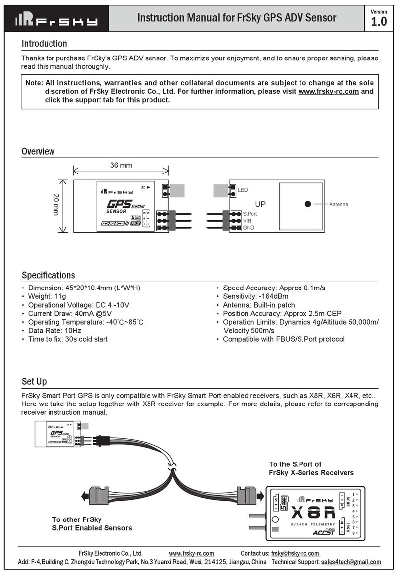
FrSky GPS ADV User manual

FrSky

FrSky GPS ADV User manual

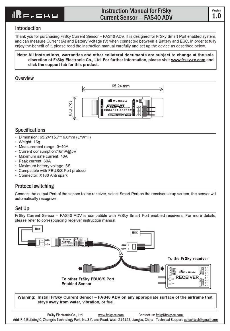
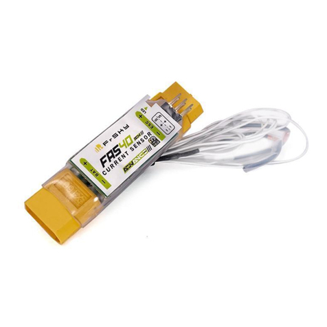
FrSky FAS40 ADV User manual

FrSky

FrSky FAS40 ADV User manual

FrSky FAS100S User manual

FrSky

FrSky FAS100S User manual

FrSky GPS ADV User manual

FrSky

FrSky GPS ADV User manual

FrSky FAS100 ADV User manual

FrSky

FrSky FAS100 ADV User manual

FrSky FAS7 ADV User manual

FrSky

FrSky FAS7 ADV User manual

FrSky X8R User manual

FrSky

FrSky X8R User manual

FrSky FAS40 ADV User manual

FrSky

FrSky FAS40 ADV User manual

FrSky PS30 ADV User manual

FrSky

FrSky PS30 ADV User manual

FrSky FAS7 ADV User manual

FrSky

FrSky FAS7 ADV User manual

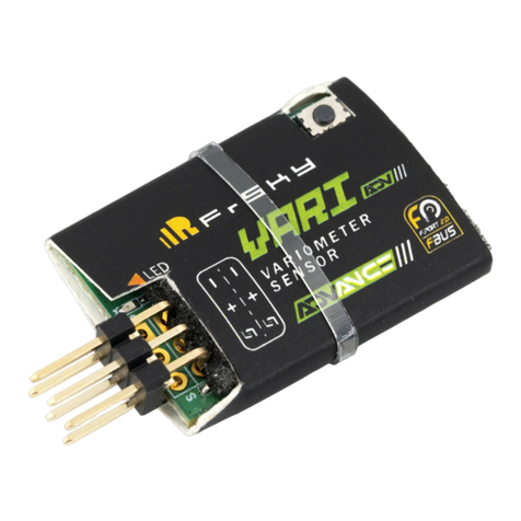
FrSky VARI ADV User manual

FrSky

FrSky VARI ADV User manual

FrSky FAS7 ADV Lite User manual

FrSky

FrSky FAS7 ADV Lite User manual

FrSky FAS7 ADV User manual

FrSky

FrSky FAS7 ADV User manual

FrSky FAS7 ADV User manual

FrSky

FrSky FAS7 ADV User manual

FrSky ADVANCE FAS40 ADV User manual

FrSky

FrSky ADVANCE FAS40 ADV User manual

Popular Accessories manuals by other brands

ARAG IBX100 4679004 Configuration and Maintenance Guide

ARAG

ARAG IBX100 4679004 Configuration and Maintenance Guide

Balluff BTL7-A5 Series user guide

Balluff

Balluff BTL7-A5 Series user guide

IMKO TRIME-PICO T3/IPH44 user manual

IMKO

IMKO TRIME-PICO T3/IPH44 user manual

Vega VEGAPULS WL 61 operating instructions

Vega

Vega VEGAPULS WL 61 operating instructions

GB Future perfect Summer cover Short instructions

GB

GB Future perfect Summer cover Short instructions

Monnit ALTA MNS2-4-PK-WS-PS user guide

Monnit

Monnit ALTA MNS2-4-PK-WS-PS user guide

Nitecore F2 user manual

Nitecore

Nitecore F2 user manual

TeleVue FocusMate TFM-2000 Installation

TeleVue

TeleVue FocusMate TFM-2000 Installation

NRG Systems Hybrid XT Vane Product guide

NRG Systems

NRG Systems Hybrid XT Vane Product guide

Huawei NetCol8000-C070 quick guide

Huawei

Huawei NetCol8000-C070 quick guide

MOB MO8113 user manual

MOB

MOB MO8113 user manual

Ocean Sonics Subsea Power Bank user guide

Ocean Sonics

Ocean Sonics Subsea Power Bank user guide

Hydas 4652.5.01 instruction manual

Hydas

Hydas 4652.5.01 instruction manual

Kopp 2931.1302.9 instruction manual

Kopp

Kopp 2931.1302.9 instruction manual

Cerlic FLX manual

Cerlic

Cerlic FLX manual

Honeywell C7232A Product data

Honeywell

Honeywell C7232A Product data

Hunter Hunter Accessory Table 20523 installation instructions

Hunter

Hunter Hunter Accessory Table 20523 installation instructions

Panasonic MA4X714 (MA714) Specification sheet

Panasonic

Panasonic MA4X714 (MA714) Specification sheet

manuals.online logo
manuals.online logoBrands
  • About & Mission
  • Contact us
  • Privacy Policy
  • Terms and Conditions

Copyright 2025 Manuals.Online. All Rights Reserved.