Seon Mobile Surveillance Explorer EX4 Plus 35 System User manual

*700-0058*
Document part number 700-0058 R001
Explorer™ EX4 Plus 35
Mobile Digital Video
Recording (DVR) System
Manual Type
Installation and User’s Guide


Seon Design® Inc.
Seon Design Inc. is a specialist in the design and manufacture of video surveillance systems for mobile applications. Seon has
been the preferred solutions provider for the pupil transportation industry since 1999. Today, we are proud that our success in
this area has made us the leading manufacturer of mobile video surveillance systems in North America.
Contact Information
Seon Design Inc.
Unit 111, 3B Burbidge Street
Coquitlam, BC
Canada V3K 7B2
Seon Design Inc. Trademarks
Seon Design Inc. holds the following trademarks:
Explorer™ is a registered trademark of Seon Design Inc.
“Seon Design” is a registered trademark of Seon Design Inc.
The Seon logo ( ) is a registered trademark of Seon Design Inc.
In this User Manual there are references to trademarks, registered trademarks, and product names not owned by Seon Design
Inc. that are the property of their respective owners. They are used in this User Manual for identification purposes only.
User Manual Revision
This is the November 2007 revision for this User Manual and is copyright, November 2007 of Seon Design Inc. All rights
reserved.
Exclusion of Liability
SEON DESIGN INC.:
(a) MAKES NO REPRESENTATION, WARRANTY, GUARANTEE OR COVENANT, EXPRESS OR IMPLIED, AS TO THE ACCURACY,
SUFFICIENCY OR SUITABILITY OF ANY TECHNICAL OR OTHER INFORMATION PROVIDED IN THIS USER MANUAL OR ANY OTHER
USER OR OTHER MANUAL OR OTHER DOCUMENTATION PROVIDED BY SEON DESIGN INC. WITH RESPECT TO THE PRODUCT(S)
DESCRIBED HEREIN, INCLUDING WITHOUT LIMITATION ANY DESCRIPTION OF GOODS OR SERVICES, SPECIFICATIONS, MODELS,
DRAWINGS, OR DIAGRAMS.
(b) DOES NOT ASSUME AND SHALL NOT BE SUBJECT TO AND DISCLAIMS ANY AND ALL RESPONSIBILITY AND/OR LIABILITY FOR
LOSSES, DAMAGES, COSTS OR EXPENSES ARISING OUT OF BREACH OF CONTRACT OR OF WARRANTY, TORT (INCLUDING
NEGLIGENCE AND STRICT LIABILITY) OR OTHERWISE, WHETHER SPECIAL, DIRECT, INDIRECT, CONSEQUENTIAL, INCIDENTAL,
SPECIAL OR CONTINGENT, WHICH MIGHT ARISE OUT OF THE USE OF SUCH INFORMATION. THE USE OF ANY SUCH INFORMATION
WILL BE ENTIRELY AT THE USER’SRISK; AND
(c) EXPRESSLY DISCLOSES THAT IF THIS MANUAL IS WRITTEN IN ANY LANGUAGE OTHER THAN ENGLISH, THAT ALTHOUGH
SEON DESIGN INC. HAS USED REASONABLE CARE TO MAINTAIN THE ACCURACY OF THE TRANSLATION FROM THE ENGLISH
LANGUAGE, THE ACCURACY OF SUCH TRANSLATION IS NOT GUARANTEED OR WARRANTED BY SEON DESIGN INC. PLEASE REFER
TO THE ENGLISH LANGUAGE VERSION OF THIS USER MANUAL FOR APPROVED SEON CONTENT. THE ENGLISH LANGUAGE
VERSION IS AVAILABLE UPON REQUEST FROM THE SEON CUSTOMER SERVICE DEPARTMENT.
Please refer to the Seon Design Inc. Product Warranty applicable to the Product(s) described in this User Manual which
exclusively sets forth Seon Design Inc.’s entire liability arising from or in connection with such product(s) and their use and
the exclusive remedies available for purchasers and users thereof.
Document Part Number
This User Manual is valid for Seon Design Inc. Document Part Number 700-0058.
PRINTED IN CANADA
Telephone 604.941.0880
Toll Free Telephone 1.877.630.7366
Fax 604.941.0870
Toll Free Fax 1.866.664.3677
Email [email protected]
Web site www.seon.com


700-0058 R001
Who This Guide is For
The Installation and User’s Guide is intended for anyone who needs to install and
operate the Explorer EX4 Plus 35 Mobile Digital Video Recording (DVR) System
(EX4 Plus 35 System).
This Guide provides information and procedures for installing, configuring,
operating, maintaining, and troubleshooting the EX4 Plus 35 System.
Conventions Used
Abbreviations and Acronyms
CAUTION
Cautions identify conditions or practices that could result in damage to the unit or to other
equipment.
Important:
These notes describe things which are important for you to know, but they
not as serious as a Caution.
Acronym Definition
DVR Digital video recorder
FPS Frames per second
GPS Global Positioning System
HD Hard drive
IPS Images per second
IR Infrared
LAN Local area network
MPEG Moving Picture Experts Group
RA Return Authorization
TCM Transmission Control Module
UTC Universal Time Coordinated

ii 700-0058 R001
Related Documentation
Refer to the following related documentation.
Finding Information Online
You can find information about Seon Design Inc,. as well as its products and
services, by visiting www.seon.com.
Document Name Document Part Number
SA Series Wedge Camera Setup Guide 700-0004
SJ Series Dome Camera Setup Guide 700-0049
HD Reader User’s Guide 700-0036
TR-INR Inertia Sensor Installation and User Guide 700-0041

700-0058 R001 iii
Chapter 1
Introduction
1.1. EX4 Plus 35 System - - - - - - - - - - - - - - - - - - - - - - - - - - - - - - - - - - - - - - - - - - - - - - - - - 1–2
1.2. EX4 Plus 35 System Product Features - - - - - - - - - - - - - - - - - - - - - - - - - - - - - - - - - - - - - 1–2
1.3. EX4 Plus 35 DVR - - - - - - - - - - - - - - - - - - - - - - - - - - - - - - - - - - - - - - - - - - - - - - - - - - - 1–3
1.3.1. DVR Front Panel Features - - - - - - - - - - - - - - - - - - - - - - - - - - - - - - - - - - - - - - - - - 1–3
1.3.2. DVR Buttons - - - - - - - - - - - - - - - - - - - - - - - - - - - - - - - - - - - - - - - - - - - - - - - - - - 1–4
1.3.3. DVR Back Panel Features - - - - - - - - - - - - - - - - - - - - - - - - - - - - - - - - - - - - - - - - - - 1–6
1.4. Lock Box - - - - - - - - - - - - - - - - - - - - - - - - - - - - - - - - - - - - - - - - - - - - - - - - - - - - - - - - - 1–7
1.5. Cables and Harnesses- - - - - - - - - - - - - - - - - - - - - - - - - - - - - - - - - - - - - - - - - - - - - - - - - 1–7
Chapter 2
Installation
2.1. Installing the EX4 Plus 35 DVR and Lock Box - - - - - - - - - - - - - - - - - - - - - - - - - - - - - - - 2–2
2.2. Step 1: Installing the Lock Box - - - - - - - - - - - - - - - - - - - - - - - - - - - - - - - - - - - - - - - - - - 2–3
2.2.1. Horizontal Installation - - - - - - - - - - - - - - - - - - - - - - - - - - - - - - - - - - - - - - - - - - - - 2–3
2.2.2. Vertical Installation - - - - - - - - - - - - - - - - - - - - - - - - - - - - - - - - - - - - - - - - - - - - - - 2–4
2.3. Step 2: Installing the DVR in the Lock Box- - - - - - - - - - - - - - - - - - - - - - - - - - - - - - - - - - 2–5
2.4. Step 3: Installing the Cameras - - - - - - - - - - - - - - - - - - - - - - - - - - - - - - - - - - - - - - - - - - - 2–6
2.4.1. Checking the Camera Cable Connections - - - - - - - - - - - - - - - - - - - - - - - - - - - - - - - 2–6
2.5. Step 4: Connecting the DVR - - - - - - - - - - - - - - - - - - - - - - - - - - - - - - - - - - - - - - - - - - - - 2–8
2.5.1. Connecting to the DVR Back Panel - - - - - - - - - - - - - - - - - - - - - - - - - - - - - - - - - - - 2–8
2.6. Step 5: Connecting the Power and Ignition Harness, Fuses, and Fuse Holders - - - - - - - - - - 2–10
2.7. Step 6: Installing the Smart-Link™ Module- - - - - - - - - - - - - - - - - - - - - - - - - - - - - - - - - 2–11
2.7.1. Connecting the Signal Harness - - - - - - - - - - - - - - - - - - - - - - - - - - - - - - - - - - - - - 2–12
2.7.2. Connecting the Speed Cable - - - - - - - - - - - - - - - - - - - - - - - - - - - - - - - - - - - - - - - 2–13
2.8. Step 7: Installing the GPS Receiver - - - - - - - - - - - - - - - - - - - - - - - - - - - - - - - - - - - - - - 2–13
2.9. Step 8: Installing the Driver’s Indicator Panel - - - - - - - - - - - - - - - - - - - - - - - - - - - - - - - 2–14
2.9.1 Status of the Driver’s Indicator Panel - - - - - - - - - - - - - - - - - - - - - - - - - - - - - - - - - - 2–14
2.10. Step 9: Hardware Installation Final Checklist- - - - - - - - - - - - - - - - - - - - - - - - - - - - - - - 2–15
2.11. TR-INR Inertia Sensor - - - - - - - - - - - - - - - - - - - - - - - - - - - - - - - - - - - - - - - - - - - - - - 2–16
2.12. CAN Network- - - - - - - - - - - - - - - - - - - - - - - - - - - - - - - - - - - - - - - - - - - - - - - - - - - - 2–16
2.13. EZN Decoy System - - - - - - - - - - - - - - - - - - - - - - - - - - - - - - - - - - - - - - - - - - - - - - - - 2–16
2.14. Wireless Network - - - - - - - - - - - - - - - - - - - - - - - - - - - - - - - - - - - - - - - - - - - - - - - - - 2–16
Contents

Contents
iv 700-0058 R001
Chapter 3
Configuring the DVR
3.1. Configuring the DVR - - - - - - - - - - - - - - - - - - - - - - - - - - - - - - - - - - - - - - - - - - - - - - - - 3–2
3.2. EX4 Plus 35 DVR Main Menu - - - - - - - - - - - - - - - - - - - - - - - - - - - - - - - - - - - - - - - - - - 3–3
3.2.1. Software Version - - - - - - - - - - - - - - - - - - - - - - - - - - - - - - - - - - - - - - - - - - - - - - - 3–4
3.2.2. Using the Time/Date Menu - - - - - - - - - - - - - - - - - - - - - - - - - - - - - - - - - - - - - - - - 3–4
3.2.3. Using the Titles/Display Menu - - - - - - - - - - - - - - - - - - - - - - - - - - - - - - - - - - - - - - 3–6
3.2.4. Using the Record Menu - - - - - - - - - - - - - - - - - - - - - - - - - - - - - - - - - - - - - - - - - - - 3–8
3.2.5. Using the Alarms Menu - - - - - - - - - - - - - - - - - - - - - - - - - - - - - - - - - - - - - - - - - - -3–13
3.2.6. Using the Timers Menu - - - - - - - - - - - - - - - - - - - - - - - - - - - - - - - - - - - - - - - - - - -3–15
3.2.7. Using the Signals Menu - - - - - - - - - - - - - - - - - - - - - - - - - - - - - - - - - - - - - - - - - - -3–17
3.2.8. Using the GPS/Speed Menu - - - - - - - - - - - - - - - - - - - - - - - - - - - - - - - - - - - - - - - -3–19
3.2.9. Using the Network Menu - - - - - - - - - - - - - - - - - - - - - - - - - - - - - - - - - - - - - - - - - -3–22
3.2.10. Using the System Menu - - - - - - - - - - - - - - - - - - - - - - - - - - - - - - - - - - - - - - - - - -3–24
3.2.11. Updating the Software Program - - - - - - - - - - - - - - - - - - - - - - - - - - - - - - - - - - - -3–26
Chapter 4
Operating the DVR
4.1. Operating and Monitoring the DVR- - - - - - - - - - - - - - - - - - - - - - - - - - - - - - - - - - - - - - - 4–2
4.1.1 Using the DVR buttons - - - - - - - - - - - - - - - - - - - - - - - - - - - - - - - - - - - - - - - - - - - 4–2
4.2. Viewing Recorded Video- - - - - - - - - - - - - - - - - - - - - - - - - - - - - - - - - - - - - - - - - - - - - - 4–4
4.2.1. Using the SHUTTLE Wheel during Playback - - - - - - - - - - - - - - - - - - - - - - - - - - - - 4–5
4.2.2. Using the ZOOM Button and JOG Wheel to Adjust the Display - - - - - - - - - - - - - - - - 4–5
4.3. Replacing the Hard Drive - - - - - - - - - - - - - - - - - - - - - - - - - - - - - - - - - - - - - - - - - - - - - 4–6
4.4. Downloading Video to a PC- - - - - - - - - - - - - - - - - - - - - - - - - - - - - - - - - - - - - - - - - - - - 4–6
4.5. Extended Operational Functions - - - - - - - - - - - - - - - - - - - - - - - - - - - - - - - - - - - - - - - - - 4–6
4.5.1. Reading CAN messages - - - - - - - - - - - - - - - - - - - - - - - - - - - - - - - - - - - - - - - - - - 4–6
4.5.2. Using the ONE-TOUCH Download option - - - - - - - - - - - - - - - - - - - - - - - - - - - - - - 4–7
4.5.3. Using the Search function - - - - - - - - - - - - - - - - - - - - - - - - - - - - - - - - - - - - - - - - - 4–7
4.5.4. Using the Copy Menu - - - - - - - - - - - - - - - - - - - - - - - - - - - - - - - - - - - - - - - - - - - -4–10
4.5.5. Turning the Buzzer Off - - - - - - - - - - - - - - - - - - - - - - - - - - - - - - - - - - - - - - - - - - -4–12
4.5.6. Using the LOCK Button - - - - - - - - - - - - - - - - - - - - - - - - - - - - - - - - - - - - - - - - - -4–12
4.6. Voltage Display - - - - - - - - - - - - - - - - - - - - - - - - - - - - - - - - - - - - - - - - - - - - - - - - - - - -4–13
4.7. Low Voltage and Low/High Temp Indicator- - - - - - - - - - - - - - - - - - - - - - - - - - - - - - - - -4–13
4.8. Advanced Smart-Temp - - - - - - - - - - - - - - - - - - - - - - - - - - - - - - - - - - - - - - - - - - - - - - -4–14
Chapter 5
Maintenance and Returning Product for Service
5.1. Maintenance - - - - - - - - - - - - - - - - - - - - - - - - - - - - - - - - - - - - - - - - - - - - - - - - - - - - - - 5–2
5.1.1. Cleaning the Lock Box - - - - - - - - - - - - - - - - - - - - - - - - - - - - - - - - - - - - - - - - - - - 5–2
5.1.2. Cleaning the Camera and Window - - - - - - - - - - - - - - - - - - - - - - - - - - - - - - - - - - - 5–2
5.1.3. Replacing the Fan Filter - - - - - - - - - - - - - - - - - - - - - - - - - - - - - - - - - - - - - - - - - - - 5–2
5.2. Returning Product for Service- - - - - - - - - - - - - - - - - - - - - - - - - - - - - - - - - - - - - - - - - - - 5–3

Contents
700-0058 R001 v
Chapter 6
Troubleshooting
6.1. Troubleshooting the EX4 Plus 35 System - - - - - - - - - - - - - - - - - - - - - - - - - - - - - - - - - - - 6–2
Appendix A
Specifications
A.1. EX4 Plus 35 DVR- - - - - - - - - - - - - - - - - - - - - - - - - - - - - - - - - - - - - - - - - - - - - - - - - - -A–2
A.2. DVR Functional Features- - - - - - - - - - - - - - - - - - - - - - - - - - - - - - - - - - - - - - - - - - - - - -A–3
A.3. Additional Features of the EX4 Plus 35 DVR - - - - - - - - - - - - - - - - - - - - - - - - - - - - - - - -A–3
A.4. Lock Box - - - - - - - - - - - - - - - - - - - - - - - - - - - - - - - - - - - - - - - - - - - - - - - - - - - - - - - -A–4
A.5. Smart-Link™ Module - - - - - - - - - - - - - - - - - - - - - - - - - - - - - - - - - - - - - - - - - - - - - - - -A–4
SEON DESIGN® INC. PRODUCT WARRANTY
DISCLAIMER - - - - - - - - - - - - - - - - - - - - - - - - - - - - - - - - - - - - - - - - - - - - - - - - - - - - - - - W–2

vi

700-0058 R001 vii
Table 1-1 Front panel features- - - - - - - - - - - - - - - - - - - - - - - - - - - - - - - - - - - - - - - - - - - - - - - 1–3
Table 1-2 Description of DVR buttons - - - - - - - - - - - - - - - - - - - - - - - - - - - - - - - - - - - - - - - - - 1–5
Table 2-1 Camera cable wiring - - - - - - - - - - - - - - - - - - - - - - - - - - - - - - - - - - - - - - - - - - - - - - 2–6
Table 2-2 Signal harness wiring- - - - - - - - - - - - - - - - - - - - - - - - - - - - - - - - - - - - - - - - - - - - - 2–12
Table 2-3 Speed cable wiring - - - - - - - - - - - - - - - - - - - - - - - - - - - - - - - - - - - - - - - - - - - - - - 2–13
Table 2-4 Driver’s indicator panel status- - - - - - - - - - - - - - - - - - - - - - - - - - - - - - - - - - - - - - - 2–14
Table 3-1 On-screen display information - - - - - - - - - - - - - - - - - - - - - - - - - - - - - - - - - - - - - - - 3–2
Table 3-2 Time/Date configuration items - - - - - - - - - - - - - - - - - - - - - - - - - - - - - - - - - - - - - - - 3–5
Table 3-3 Titles/Display configuration items - - - - - - - - - - - - - - - - - - - - - - - - - - - - - - - - - - - - - 3–7
Table 3-4 Record configuration items- - - - - - - - - - - - - - - - - - - - - - - - - - - - - - - - - - - - - - - - - - 3–9
Table 3-5 Picture quality settings- - - - - - - - - - - - - - - - - - - - - - - - - - - - - - - - - - - - - - - - - - - - 3–10
Table 3-6 Estimated recording time in hours with 80 GB hard drive - - - - - - - - - - - - - - - - - - - - 3–11
Table 3-7 Estimated recording time in hours with 500 GB hard drive - - - - - - - - - - - - - - - - - - - 3–12
Table 3-8 Estimated recording time in hours with 750 GB hard drive - - - - - - - - - - - - - - - - - - - 3–12
Table 3-9 Alarm configuration items - - - - - - - - - - - - - - - - - - - - - - - - - - - - - - - - - - - - - - - - - 3–14
Table 3-10 Alarm 1 settings configuration items - - - - - - - - - - - - - - - - - - - - - - - - - - - - - - - - - - 3–14
Table 3-11 Timers configuration items- - - - - - - - - - - - - - - - - - - - - - - - - - - - - - - - - - - - - - - - - 3–16
Table 3-12 Signal configuration items - - - - - - - - - - - - - - - - - - - - - - - - - - - - - - - - - - - - - - - - - 3–18
Table 3-13 GPS/SPEED configuration items- - - - - - - - - - - - - - - - - - - - - - - - - - - - - - - - - - - - - 3–20
Table 3-14 Network configuration items- - - - - - - - - - - - - - - - - - - - - - - - - - - - - - - - - - - - - - - - 3–23
Table 3-15 System configuration items- - - - - - - - - - - - - - - - - - - - - - - - - - - - - - - - - - - - - - - - - 3–25
Table 4-1 Using the DVR buttons - - - - - - - - - - - - - - - - - - - - - - - - - - - - - - - - - - - - - - - - - - - - 4–3
Table 4-2 Event types - - - - - - - - - - - - - - - - - - - - - - - - - - - - - - - - - - - - - - - - - - - - - - - - - - - - 4–9
Table 4-3 Search menu configuration items- - - - - - - - - - - - - - - - - - - - - - - - - - - - - - - - - - - - - 4–10
Table 4-4 Copy menu configuration items- - - - - - - - - - - - - - - - - - - - - - - - - - - - - - - - - - - - - - 4–11
Table 4-5 LOW VOLTAGE/LOW/HIGH TEMP indicator - - - - - - - - - - - - - - - - - - - - - - - - - - 4–13
Table 4-6 Advanced Smart-Temp features- - - - - - - - - - - - - - - - - - - - - - - - - - - - - - - - - - - - - - 4–14
Tables

viii

700-0058 R001 ix
Figure 1-1 EX4 Plus 35 DVR front panel - - - - - - - - - - - - - - - - - - - - - - - - - - - - - - - - - - - - - - - - 1–3
Figure 1-2 Back panel- - - - - - - - - - - - - - - - - - - - - - - - - - - - - - - - - - - - - - - - - - - - - - - - - - - - - 1–6
Figure 2-1 Lock box horizontal installation - - - - - - - - - - - - - - - - - - - - - - - - - - - - - - - - - - - - - - 2–4
Figure 2-2 Lock box vertical installation - - - - - - - - - - - - - - - - - - - - - - - - - - - - - - - - - - - - - - - - 2–5
Figure 2-3 Brackets and cable retainers - - - - - - - - - - - - - - - - - - - - - - - - - - - - - - - - - - - - - - - - - 2–5
Figure 2-4 Terminal blocks in the camera- - - - - - - - - - - - - - - - - - - - - - - - - - - - - - - - - - - - - - - - 2–6
Figure 2-5 Back panel connections - - - - - - - - - - - - - - - - - - - - - - - - - - - - - - - - - - - - - - - - - - - - 2–8
Figure 2-6 Smart-Link-to-DVR connection harness - - - - - - - - - - - - - - - - - - - - - - - - - - - - - - - - - 2–9
Figure 2-7 Power and ignition harness wires- - - - - - - - - - - - - - - - - - - - - - - - - - - - - - - - - - - - - 2–10
Figure 2-8 Smart-Link module - - - - - - - - - - - - - - - - - - - - - - - - - - - - - - - - - - - - - - - - - - - - - - 2–11
Figure 2-9 3-foot Smart-Link signal harness - - - - - - - - - - - - - - - - - - - - - - - - - - - - - - - - - - - - - 2–12
Figure 2-10 20-foot Smart-Link speed cable- - - - - - - - - - - - - - - - - - - - - - - - - - - - - - - - - - - - - - 2–13
Figure 2-11 Driver’s indicator panel - - - - - - - - - - - - - - - - - - - - - - - - - - - - - - - - - - - - - - - - - - - 2–14
Figure 3-1 On-screen display during live viewing and recording - - - - - - - - - - - - - - - - - - - - - - - - 3–2
Figure 3-2 Main menu- - - - - - - - - - - - - - - - - - - - - - - - - - - - - - - - - - - - - - - - - - - - - - - - - - - - - 3–3
Figure 3-3 Time/Date menu - - - - - - - - - - - - - - - - - - - - - - - - - - - - - - - - - - - - - - - - - - - - - - - - - 3–4
Figure 3-4 Titles/Display menu - - - - - - - - - - - - - - - - - - - - - - - - - - - - - - - - - - - - - - - - - - - - - - 3–6
Figure 3-5 Record menu - - - - - - - - - - - - - - - - - - - - - - - - - - - - - - - - - - - - - - - - - - - - - - - - - - - 3–8
Figure 3-6 Alarms menu - - - - - - - - - - - - - - - - - - - - - - - - - - - - - - - - - - - - - - - - - - - - - - - - - - 3–13
Figure 3-7 Alarm settings sub-menu - - - - - - - - - - - - - - - - - - - - - - - - - - - - - - - - - - - - - - - - - - 3–13
Figure 3-8 Timers menu - - - - - - - - - - - - - - - - - - - - - - - - - - - - - - - - - - - - - - - - - - - - - - - - - - 3–16
Figure 3-9 Signals menu - - - - - - - - - - - - - - - - - - - - - - - - - - - - - - - - - - - - - - - - - - - - - - - - - - 3–17
Figure 3-10 GPS/Speed menu - - - - - - - - - - - - - - - - - - - - - - - - - - - - - - - - - - - - - - - - - - - - - - - 3–19
Figure 3-11 Network menu - - - - - - - - - - - - - - - - - - - - - - - - - - - - - - - - - - - - - - - - - - - - - - - - - 3–22
Figure 3-12 System menu - - - - - - - - - - - - - - - - - - - - - - - - - - - - - - - - - - - - - - - - - - - - - - - - - - 3–24
Figure 3-13 Export defaults popup menu - - - - - - - - - - - - - - - - - - - - - - - - - - - - - - - - - - - - - - - - 3–27
Figure 3-14 Program update popup menu- - - - - - - - - - - - - - - - - - - - - - - - - - - - - - - - - - - - - - - - 3–28
Figure 3-15 Load defaults popup menu - - - - - - - - - - - - - - - - - - - - - - - - - - - - - - - - - - - - - - - - - 3–29
Figure 3-16 Import defaults popup menu - - - - - - - - - - - - - - - - - - - - - - - - - - - - - - - - - - - - - - - - 3–29
Figure 3-17 Format hard-drive popup menu - - - - - - - - - - - - - - - - - - - - - - - - - - - - - - - - - - - - - - 3–30
Figure 4-1 Front panel DVR buttons - - - - - - - - - - - - - - - - - - - - - - - - - - - - - - - - - - - - - - - - - - - 4–2
Figure 4-2 Search menu- - - - - - - - - - - - - - - - - - - - - - - - - - - - - - - - - - - - - - - - - - - - - - - - - - - - 4–8
Figure 4-3 Copy menu - - - - - - - - - - - - - - - - - - - - - - - - - - - - - - - - - - - - - - - - - - - - - - - - - - - 4–11
Figure 5-1 Replacing the fan filter- - - - - - - - - - - - - - - - - - - - - - - - - - - - - - - - - - - - - - - - - - - - - 5–2
Figures

x

CHAPTER 1
Introduction
This chapter describes the product features and components of the Explorer
EX4 Plus 35 Mobile Digital Video Recording (DVR) System
(EX4 Plus 35 System).

Introduction
1–2 700-0058 R001
1.1. EX4 Plus 35 System
The EX4 Plus 35 System consists of the following components:
•EX4Plus35DVR
• Lock box
• Cameras
•Harddrive
• Driver’s indicator panel (video recording label optional)
• GPS (Global Positioning System) (if purchased)
• Smart-Link™ module
• Cables and harnesses for power, ignition input, Smart-Link interface, alarms
and signals
1.2. EX4 Plus 35 System Product Features
The EX4 Plus 35 System has been designed using extremely reliable and easy-to-
use technology, including:
• Rugged digital video recorder
• MPEG-4 compression
• Four video channels and two audio channels
• Selectable image quality, resolution, and recording rate
• Replaceable/upgradeable hard drives to extend recording times
• Downloadable images and video using USB memory devices
• On-screen display of time, date, vehicle identification, and system voltage
• Integrated Ethernet network connection for LAN interfaces or other high-speed
expansion devices
• Smart-Start™ to prevent potential damage from voltage spikes and drops
during vehicle start-up
• Advanced Smart-Temp™ and built-in heater to ensure safe operation over a
wide temperature range
• Smart-Link™ module for signal interfaces, including:
• GPS data and vehicle speed
• Ten different input signals, including CAN signals
• Driver’s indicator panel
• 4 different event alarm inputs
• Configurable software
• Repeat recording, user selectable ON or OFF
• Variable record delay-on and record delay-off recording, selectable up to 60
minutes
• Twelve daily/weekly timers to set DVR recording time
• Temporary power for setup and playback
• Front panel video output jack for setup and playback
Introduction
700-0058 R001 1–3
1.3. EX4 Plus 35 DVR
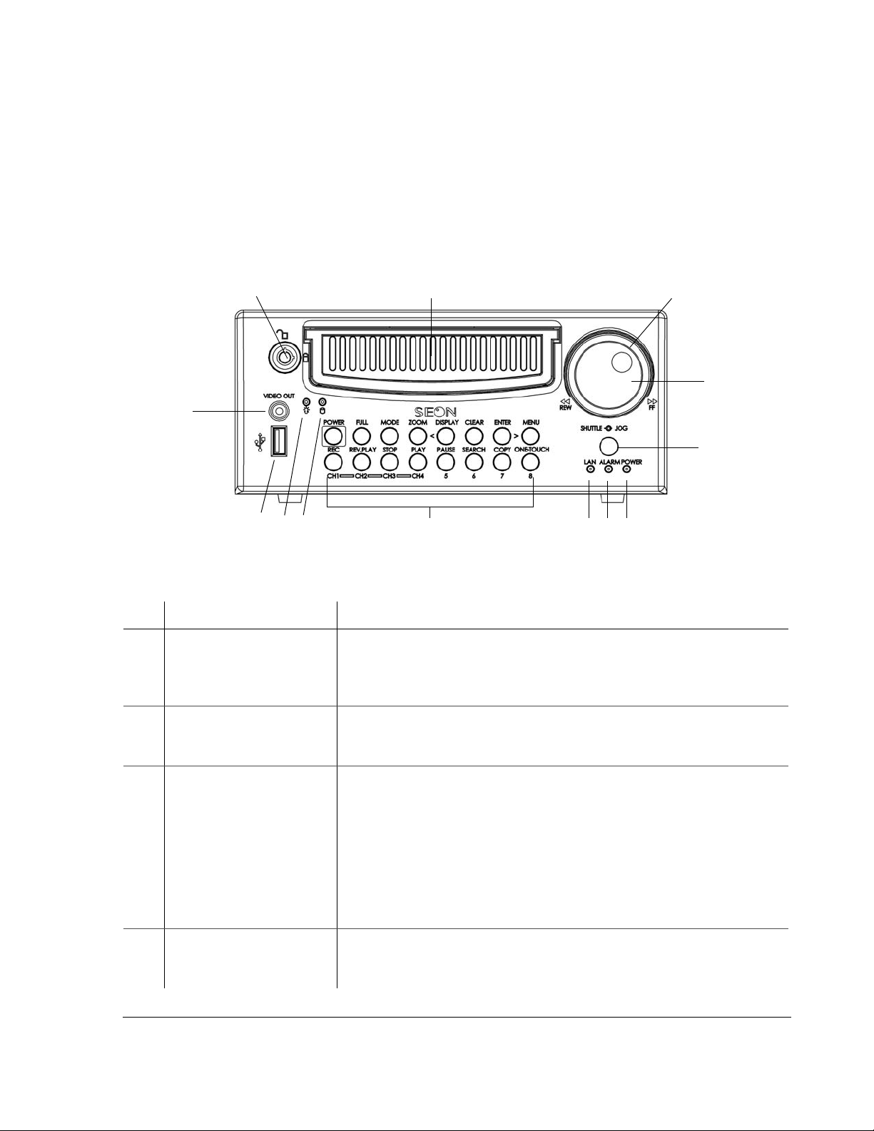
1.3.1. DVR Front Panel Features
The EX4 Plus 35 DVR front panel has important features such as the hard drive
lock, removable hard drive, SHUTTLE/JOG wheel, indicator lights, the DVR
buttons, the USB port, and the VIDEO OUT jack. See Figure 1-1.
Figure 1-1
EX4 Plus 35 DVR front panel
Table 1-1
Front panel features
Item Feature Description
1 Hard Drive lock (Unlocked
and locked positions) Requires the proper key to unlock the hard drive prior to removing
and locking the hard drive during operation. When the DVR is recording,
press the STOP button before unlocking and removing the hard drive. (For
more information, see “4.3. Replacing the Hard Drive” on page 4–6.)
2 Removable Hard Drive Remove the hard drive for playback at a remote location using the HD
Reader (see “4.4. Downloading Video to a PC” on page 4–6), swap to
another DVR, or upgrade to a larger hard drive.
3SHUTTLE wheel
(outer wheel) • During playback, turning the SHUTTLE wheel clockwise speeds the play
forward from 1× to 2×, 4×, 6×, 8×, 16× and 32× the normal speed.
• During reverse playback, turning the SHUTTLE wheel counter clockwise
speeds the play backward from 1×, 2×, 4×, 6×, 8×, 16× and 32× the
normal speed.
• When the PAUSE button is pressed, turning the SHUTTLE wheel clockwise
reduces the play to a very slow forward rate.
• When the PAUSE button is pressed, turning the SHUTTLE wheel counter
clockwise reduces the play to a very slow backward rate.
4JOG wheel (inner wheel) • Used to change the values of menu items.
• When PAUSE button is pressed, turning the JOG wheel clockwise or
counter clockwise moves the image one at a time.
123
4
5
6
7
8
10
12 11
13
9

Introduction
1–4 700-0058 R001
1.3.2. DVR Buttons
The DVR buttons on the front panel illuminate when the buttons are activated.
The DVR buttons perform more than one function and are described briefly in
Table 1-2.
Chapter 4, “Operating the DVR” provides detailed information on using the DVR
buttons. See “4.1.1 Using the DVR buttons” on page 4–2.
5 Infrared (IR) Remote
Control receiver Used with the optional IR remote control pointed at the receiver.
6POWER—DVR Power
indicator (green) Illuminates when the DVR is powered up.
7ALARM—Alarm Event
indicator (red) Illuminates when an external alarm input has been initiated and remains
illuminated for the duration of the alarm.
8LAN—Network indicator
(red) Illuminates when connected to an active network.
9 DVR Buttons See Table 1-2.
10 Hard Drive Access
indicator (yellow) Illuminates when the DVR is accessing the hard drive.
11 Hard Drive Power indicator
(green) Illuminates when the hard drive has been properly inserted in the hard drive
tray, and the hard drive lock is in the locked position.
12 USB Port Supports USB devices for:
• Copying video and audio information.
• Exporting video clips (See “4.5.2. Using the ONE-TOUCH Download
option” on page 4–7.)
• Updating the DVR software.
• Importing/exporting operating settings and profiles.
13 VIDEO OUT—Video Output
jack (yellow) VIDEO OUT jack has the same function as the VIDEO OUT jack on the back of
the DVR. Only one device at a time can be connected to either jack.
VIDEO OUT jack is used for:
• Live viewing
• Playback
• System configuration
Table 1-1
Front panel features
Item Feature Description

Introduction
700-0058 R001 1–5
Table 1-2
Description of DVR buttons
Button Description
POWER With the vehicle ignition turned OFF and the DVR powered off, pressing the POWER button
for 3 seconds powers up the DVR, but does not initiate recording.
With the vehicle ignition turned OFF and the DVR still powered up in the RECORD DELAY-
OFF interval, pressing the POWER button for 5 seconds powers down the DVR immediately.
With the vehicle ignition turned ON, pressing the POWER button for 5 seconds during the
RECORD DELAY-ON interval powers up the DVR and starts recording.
FULL Use the FULL button in combination with one of the four camera buttons (CH1, CH2, CH3, or
CH4), and the DVR displays the selected camera in full screen display mode.
MODE Pressing the MODE button changes the display.
ZOOM In full screen display mode, pressing the ZOOM button zooms into the screen 2×.
DISPLAY <
<
While the DVR is recording in live mode, different information can be displayed on the
screen.
The <button is used to navigate the menus while configuring the DVR.
CLEAR When configuring the DVR, pressing the CLEAR button loads the factory default value into
the field being edited.
LOCK >
>
Pressing the LOCK button enables a One-Time password option.
The >button is used to navigate the menus while configuring.
MENU Pressing the MENU button enters and exits the main menu of the DVR.
REC (CH1) Pressing the REC button starts the DVR recording if the DVR is not playing video or in the
menus. When the DVR is recording, the REC button is illuminated.
REV.PLAY (CH2) During playback or when the video is stopped, pressing the REV.PLAY button starts playing
the video in reverse.
STOP (CH3) Pressing the STOP button stops the DVR from recording or playing.
PLAY (CH4) If the DVR is not recording, pressing the PLAY button starts to play the recorded video and
audio.
PAUSE (5) Pressing the PAUSE button pauses the video playback and provides a still frame video
image.
SEARCH (6) Pressing the SEARCH button provides a power search function to quickly find the desired
information. Exit the Search menu by pressing the MENU button.
COPY (7) Pressing the COPY button take you to the Copy menu. Exit the Copy menu by pressing the
MENU button.
ENTER/ONE-TOUCH (8) While configuring in the menus, pressing the ENTER button lets you navigate to the
selected sub-menu.
Pressing the ONE-TOUCH button starts One-touch download. For more information, see
“4.5.2. Using the ONE-TOUCH Download option” on page 4–7.

Introduction
1–6 700-0058 R001
1.3.3. DVR Back Panel Features
The back panel of the EX4 Plus 35 DVR features the inputs where the DVR
connects to the other components of the EX4 Plus 35 System. See Figure 1-2.
Chapter 2, “Installation” provides detailed information on connecting to the back
panel. See “2.5.1. Connecting to the DVR Back Panel” on page 2–8.
Figure 1-2
Back panel
Item Feature Description
1CAMERAS Camera input connectors: 6-pin mini-DIN
2LOW VOLTAGE
LOW/HIGH TEMP Low voltage and Low/High temperature indicator (red)
3ALARM IN Alarm input connector: 2-pin
4POWER IN Power input connector: 4-pin
5CONTROL Control connector: 2-pin
6ETHERNET Network connector: RJ-45
7VIDEO OUT Video output jack: Yellow RCA style
8AUDIO IN 1, 2
AUDIO OUT 1, 2 Audio input jacks: White RCA style for Audio In
Audio output jacks: Red RCA style for Audio Out
9POWER 1
POWER 2 Auxiliary Power jacks: 2.1 mm barrels
10 FAN Fan with filter and removable cover
12
3
1
0
4
5
67
8
99
Table of contents
Other Seon Mobile Surveillance DVR manuals

Popular DVR manuals by other brands

Panasonic
Panasonic Showstopper PV-HS2000 operating instructions

Luma
Luma LUM-500-NVR Series quick start guide

Digiop
Digiop BLK-DH200400D user manual

D-Link
D-Link mydlink DNR-202L/A2A user manual

Mace
Mace MSP-19LCD8CAM4 Technical specifications

ClearView
ClearView 10.2-inch Combo Digital Video Recorder quick start guide


