ClearView 10.2-inch Combo Digital Video Recorder User manual

10.2-inch Combo Digital Video Recorder
Quick Start Guide
V 3.0.0

i
Table of Contents
1Hardware Installation and Connection..........................................................................1
1.1 Check Unpacked Combo DVR ............................................................................1
1.2 About Front Panel and Rear Panel.....................................................................1
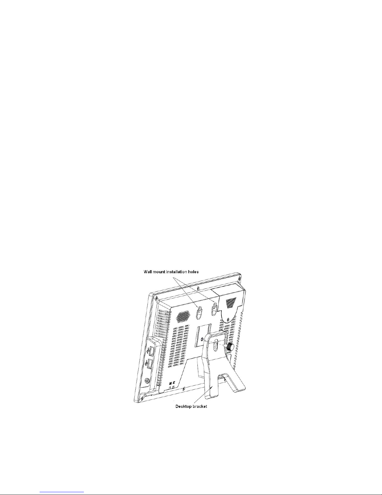
1.3 Device Installation..................................................................................................1
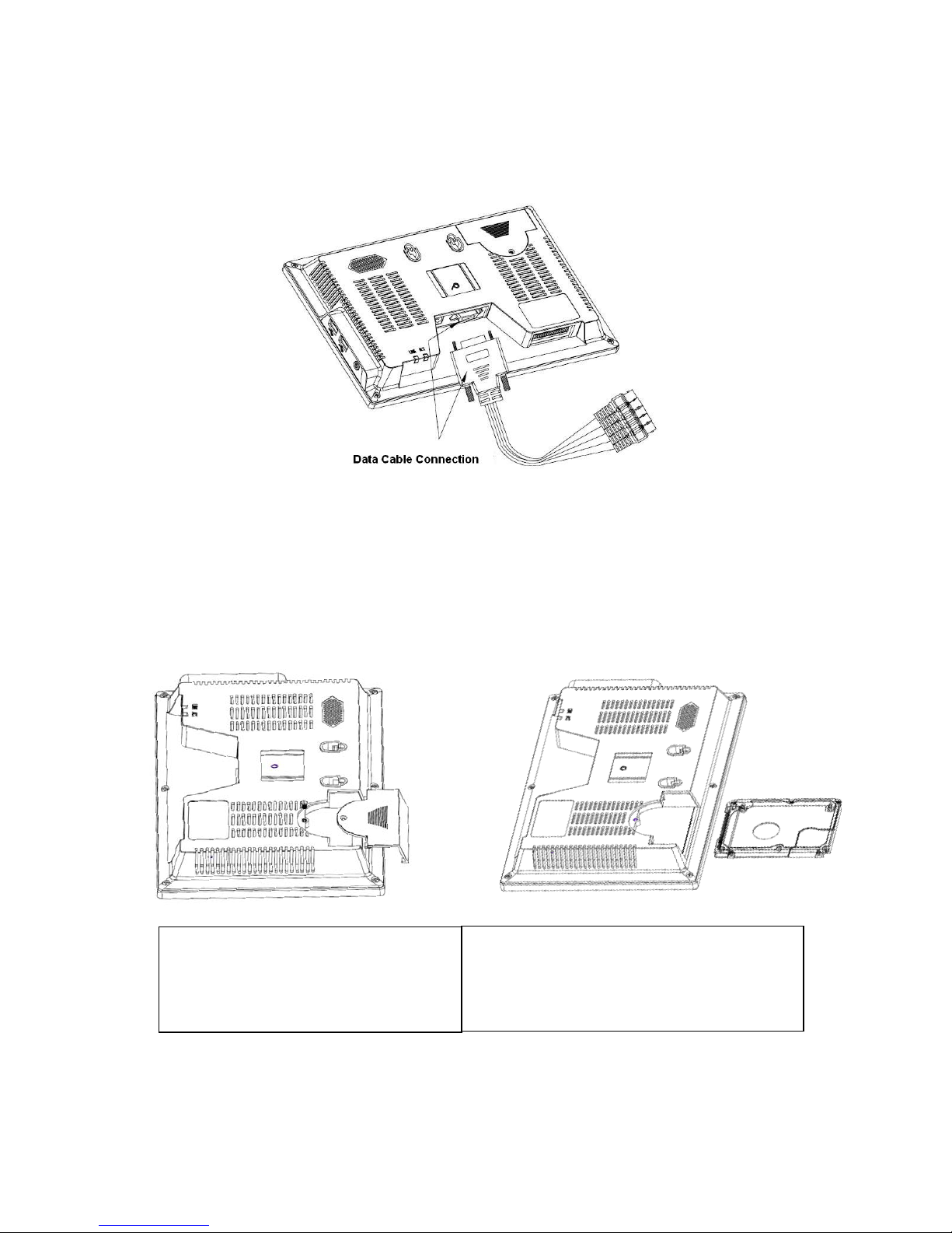
1.4 Data Cable Connection.........................................................................................1
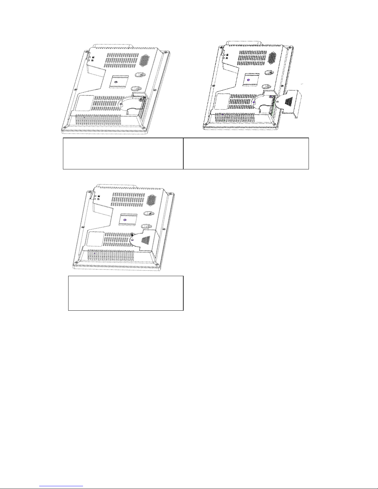
1.5 HDD Installation .....................................................................................................2
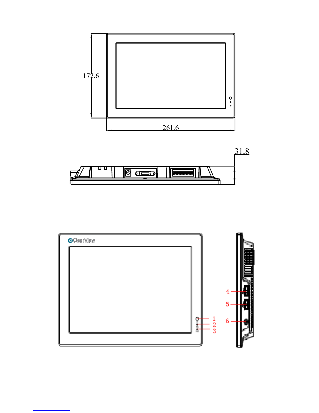
1.6 Dimensions .............................................................................................................3
1.7 Front Panel, Side Panel and Rear Panel...........................................................4
1.8 Connection Sample ...............................................................................................5
1.9 Alarm Input and Output Connection ...................................................................6
1.9.1 Alarm Input and Output Details.................................................................6
1.9.2 Alarm Input Port...........................................................................................7
1.9.3 Alarm Output Port........................................................................................7
2Overview of Navigation and Controls............................................................................8
2.1 Login, Logout & Main Menu .................................................................................8
2.1.1 Login..............................................................................................................8
2.1.2 Main Menu....................................................................................................9
2.1.3 Shutdown......................................................................................................9
2.1.4 Auto Resume after Power Failure ..........................................................10
2.1.5 Replace Button Battery ............................................................................10
2.2 Live Viewing..........................................................................................................10
2.3 Schedule ...............................................................................................................11
2.4 Manual Record.....................................................................................................12
2.5 Encode ..................................................................................................................12
2.5.1 Snapshot.....................................................................................................14
2.5.2 Image FTP..................................................................................................15
2.6 Search and Playback ..........................................................................................15

ii
2.7 Network Setup......................................................................................................18
2.8 Pan/Tilt/Zoom .......................................................................................................19
2.8.1 PTZ Setup ..................................................................................................19
2.8.2 PTZ Operation ...........................................................................................20
2.8.3 3D Intelligent Positioning Key .................................................................21
3Web Operation................................................................................................................22
3.1 Network Connection ............................................................................................22
3.2 Login ......................................................................................................................22
3.3 Main Window ........................................................................................................22
4Appendix Toxic or Hazardous Materials or Elements ..............................................24

iii
Welcome
Thank you for purchasing our combo DVR!
This quick start guide will help you become familiar with our combo DVR in a very short time.
Here you can find hardware installation,cable connection information and general operations
such as system setup, record, search, backup, alarm setup, PTZ operation, also here you can
find web operation instruction.
Before installation and operation, please read the following safeguard and warning carefully!

iv
Important Safeguards and Warnings
1.Electrical safety
All installation and operation here should conform to your local electrical safety codes.
We assume no liability or responsibility for all the fires or electrical shock caused by improper
handling or installation.
2.Transportation security
Heavy stress, violent vibration or water splash are not allowed during transportation, storage and
installation.
3.Installation
Keep upwards. Handle with care.
Do not apply power to the combo DVR before completing installation.
Do not place objects on the combo DVR.
4.Qualified engineers needed
All the examination and repair work should be done by the qualified service engineers.
We are not liable for any problems caused by unauthorized modifications or attempted repair.
5.Environment
This series product working temperature ranges from -5℃to 55℃.
The combo DVR should be installed in a cool, dry place away from direct sunlight, inflammable,
explosive substances and etc.
Please unplug the power cable in case there is strong wind or lightning.
6. Accessories
Be sure to use all the accessories recommended by manufacturer.
Before installation, please open the package and check all the components are included.
Contact your local retailer ASAP if something is broken in your package.
7. About the LCD
During the installation, do not push or squeeze the LCD or its rim; it may result in LCD damage.
During the operation or storage, please avoid the hard object to scuff the screen.
Please keep the LCD clean. Use the soft cloth to clean regularly. Do not use gasoline, alcohol or
other chemical reagent to clean the screen.
Do not allow the LCD video standstill for a long time; it may result in permanent damage.
7. Lithium battery
Improper battery use may result in fire, explosion, or personal injury!
When replace the battery, please make sure you are using the same model!

1
1Hardware Installation and Connection
Note: All the installation and operations here should conform to your local
electric safety rules.
1.1 Check Unpacked Combo DVR
When you receive the combo DVR from the forwarding agent, please check whether there is any
visible damage. The protective materials used for the package of the combo DVR can protect
most accidental clashes during transportation. Then you can open the box to check the
accessories.
Please check the items in accordance with the list on the warranty card. Finally you can remove
the protective film of the combo DVR.
Note
Remote control is not a standard accessory and it is not included in the accessory bag.
1.2 About Front Panel and Rear Panel
The model in the front panel is very important; please check according to your purchase order.
The label in the rear panel is very important too. Usually we need you to represent the serial
number when we provide the service after sales.
1.3 Device Installation
The series product supports two installation modes: desktop/ wall-mount. The default installation
is the desktop type. Please refer to the following figure. See Figure 1-1.
Figure 1-1
1.4 Data Cable Connection

2
You can refer to the following figure for cable connection. See Figure 1-2.
Please use the screwdriver to secure the data cable and the combo DVR cable socket. Please
make sure it is firm otherwise it may result in network problem and etc. Then you can use the
Ping command to test the network cable connection status. You need to check the cable
connection if the request time is out.
Figure 1-2
1.5 HDD Installation
This series 10.2-inch combo DVR has only one 2.5-inch SATA HDD.
You can refer to the Appendix in the user’s manual for recommended HDD brand. You can select
the capacity as your requirement.
Please follow the instructions below to install the HDD.
1. Turn the screw of the HDD cover and
then remove the HDD cover
2. Line up the HDD to the HDD slot and then
install

3
1.6 Dimensions
You can refer to the following two figures for dimension information. The unit is mm. See Figure
1-3 and Figure 1-4.
3. Fix the HDD 4. Install the HDD cover.
5. Secure the screw of the HDD cover.
Now the installation completed

4
Figure 1-3
Figure 1-4
1.7 Front Panel, Side Panel and Rear Panel
The front panel and side panel is shown as in Figure 1-5.
Figure 1-5
The rear panel is shown as below. See Figure 1-6.

5
Figure 1-6
Please refer to the following sheet for front panel button information.
SN Name Function
1 Remote control signal
receive window.
It is to receive the signal from the remote
control.
2 HDD indication light The light is on when systems is reading or
write the HDD data.
3 Power indication light The light is on when the device is connected to
the power.
4/5 USB port /
When the device is off, press it for a long time
to boot up the device.
When the device is on press it for a long time
to shut down the device.
6 On/off button
When the device is off, press it for a short time
to close/open the screen.
7 Network status indication
light
/
8 Power socket port Connect to DC 12V power
9 Cable port Video CVBS input, audio CVBS input, video
CVBS output, audio CVBS output, RJ45 port.
10 Power socket Alarm input, alarm output, RJ-45 port, RS-232
port.
1.8 Connection Sample
Please refer to Figure 1-7 for connection sample.
T The following figure is based on the 8-channel series product.

6
Figure 1-7
1.9 Alarm Input and Output Connection
There are two alarm input types for you to select: normal open (NO) and normal close (NC).
1.9.1 Alarm Input and Output Details
Figure 1-8
You can refer to the following sheet and Figure 1-8 for alarm input and output information.
Parameter
Grounding Alarm
Ground line
AB Connection
port

7
1, 2, 3, 4. Alarm input 1 to alarm input 4. It becomes valid in low voltage.
NO C A group of normal open activation output.
Rx,TX It is RS232 port to connect to the COM (debug), keyboard port and
transparent port (transfer COM input and output via the network).
A/B RS485 communication port. They are used to control devices such
as PTZ. Please parallel connect 120TΩbetween A/B cables if there
are too many PTZ decoders.T
1.9.2 Alarm Input Port
Please refer to the following sheet for more information.
z4-channel alarm input. Normal open or Normal close type.
zPlease parallel connect COM end and GND end of the alarm detector (Provide external
power to the alarm detector).
zPlease parallel connect the Ground of the combo DVR and the ground of the alarm detector.
zPlease connect the NC port of the alarm sensor to the combo DVR alarm input(ALARM)
zUse the same ground with that of combo DVR if you use external power to the alarm device.
Figure 1-9
1.9.3 Alarm Output Port
z1-channel relay alarm output (NO contact). Provide external power to external alarm device.
zTo avoid overloading, please read relay parameters sheet in the User’s Manual carefully.
zRS485 A/B cable is for the A/B cable of the PTZ decoder.

8
2Overview of Navigation and Controls
Before operation, please make sure you have properly installed HDD and all the cable
connections.
2.1 Login, Logout & Main Menu
2.1.1 Login
Connect the power cable and the press the power button at the rear panel. You can see the
power indication light is on and the DVR is booting up. The system goes to multiple-window
display mode by default. You can see the corresponding channel record indication light is on if it
is in the schedule record period.
After system booted up, system pops up the startup wizard.
Click the Cancel button; you can go to the system login interface.
Click the Next Step button; you can go to the startup wizard interface. Here you can set the
system basic information. See Figure 2-1.
Figure 2-1
The system login interface is shown as in Figure 2-2.
System consists of four accounts:
zUsername: admin. Password: admin. (administrator, local and network)
zUsername: 888888. Password: 888888. (administrator, local only)
zUsername: 666666. Passwords: 666666(Lower authority user who can only monitor, playback,
backup and etc.)
zUsername: default. Password: default(hidden user)
You can use USB mouse, front panel, remote control or keyboard to input. About input method:
Click to switch between numeral, English character (small/capitalized) and denotation.
Note:
For security reason, please modify password after you first login.
Within 30 minutes, three times login failure will result in system alarm and five times login failure
will result in account lock!

9
Figure 2-2
2.1.2 Main Menu
After you logged in, the system main menu is shown as below. See Figure 2-3.
There are total six icons: search, information, setting, backup, advanced and shutdown.
You can move the cursor to highlight the icon, and then double click mouse to enter the sub-
menu.
Figure 2-3
2.1.3 Shutdown
Important
Please open the HDD cover and then cut off the power before you replace the HDD!
There are two ways for you to shutdown the device.
The first one is from menu option (recommended):
In the main menu, click shutdown button, you can see an interface is shown as below. See
Figure 2-4.
Figure 2-4
There are several options for you. See Figure 2-5.
Please select the shutdown item to turn off the combo DVR.

10
Figure 2-5
The other way is to press power button on the side panel to turn off the device.
2.1.4 Auto Resume after Power Failure
The system can automatically backup video and resume previous working status after power
failure.
2.1.5 Replace Button Battery
Please make sure to use the same battery model if possible.
Please contact your local retailer before you replace the battery.
We recommend replace battery regularly (such as one-year) to guarantee system time
accuracy.
Before replacement, please save the system setup, otherwise, you may lose the data
completely!
2.2 Live Viewing
After you logged in, the system is in live viewing mode by default. You can see system date, time
and channel name. If you want to change system date and time, you can refer to general settings
(Main Menu->Setting->General). If you want to modify the channel name, please refer to the
display settings (Main Menu->Setting->Display)
Navigation Bar
In the preview interface, you can see the following navigation bar. See Figure 2-6.
Figure 2-6
Please refer to the following sheet for detailed information.
1 Go to the main menu. 8 Search
2 Hide navigation bar. 9 Alarm output
3
One-window preview
channel 10 Record control
1 Recording status 3 Video loss
2 Motion detection 4 Camera lock

11
4
Four-window preview
channel 11 Volume
5
Eight-window preview
channel 12 Color
6
Nine-window preview
channel 13 Network
7 PTZ setup 14 HDD management
2.3 Schedule
Note:
You need to have proper rights to implement the following operations. Please make sure the
HDD have been properly installed.
After the system booted up, it is in default 24-hour regular mode. You can set record type and
time in schedule interface.
In the main menu, from Setting to Schedule, you can go to schedule menu. See Figure 2-7.
There are total six periods.
zChannel: Please select the channel number first. You can select “all”if you want to set for
the whole channels.
zWeek day: There are eight options: ranges from Saturday to Sunday and all.
zPre-record: System can pre-record the video before the event occurs into the file. The value
ranges from 1 to 30 seconds depending on the bit stream.
zSnapshoot: You can enable this function to snapshoot image when alarm occurs. (Note: This
function is for 4-channel series only. The 8-channel series product does not support the
schedule snapshot function.)
zRecord types: There are four types: regular, motion detection (MD), Alarm, MD & alarm.
Please highlight icon to select the corresponding function. After completing all the setups
please click save button, system goes back to the previous menu.
At the bottom of the menu, there are color bars for your reference. Green color stands for
regular recording, yellow color stands for motion detection and red color stands for alarm
recording. The white means the MD and alarm record is valid. Once you have set to record
when the MD and alarm occurs, system will not record neither motion detect occurs nor the
alarm occurs.

12
Figure 2-7
2.4 Manual Record
Note:
Please make sure you have the record operation right and you have properly installed the
formatted HDD.
You can right click mouse or in the main menu, from Advanced->Manual Record to go to record
interface.
There are three statuses: schedule/manual/stop. Highlight icon“○” to select corresponding
channel. See Figure 2-8.
zManual: The highest priority. After manual setup, all selected channels will begin ordinary
recording.
zSchedule: Channel records as you have set in recording setup (Main Menu->Setting-
>Schedule)
zStop: All channels stop recording.
Figure 2-8
2.5 Encode
Encode interface is shown as in Figure 2-9.
zChannel: Select the channel you want.
zCompression: System supports H.264.
zType: Please select from the dropdown list. There are three options: regular/motion
detect/alarm. You can set the various encode parameters for different record types.

13
zResolution: System supports various resolutions, you can select from the dropdown list. For
this model, main stream supports D1/2CIF/CIF/QCIF. Please note the resolution may vary
due to different channels. The extra stream supports QCIF/CIF only.
zFrame rate: It ranges from 1f/s to 25f/s in NTSC mode and 1f/s to 30f/s in PAL mode.
zBit rate type: system supports two types: CBR and VBR. In VBR mode, you can set video
quality.
zQuality: There are six levels ranging from 1 to 6. The sixth level has the highest image
quality.
zVideo/audio: you can enable or disable the video/audio. Please note the video is enabled for
main stream by default. For extra stream, please enable video first and then enable audio.
zSnapshot: Click snapshot button, you can see it contains the four items: mode/image
size/image quality/snapshot frequency. Please refer to chapter 2.3.3 for detail information.
zOverlay: Click overlay button, you can see an interface is shown in Figure 2-10.
Cover area (Privacy mask): Here is for you to set privacy mask section. You can drag you
mouse to set proper section size. In one channel video, system max supports 4 zones.
Preview/monitor: privacy mask has two types. Preview and Monitor. Preview means the
privacy mask zone can not be viewed by user when system is in preview status. Monitor
means the privacy mask zone can not be view by the user when system is in monitor status.
Time display: You can select system displays time or not when you playback. Please click
set button and then drag the title to the corresponding position in the screen.
Channel display: You can select system displays channel number or not when you playback.
Please click set button and then drag the title to the corresponding position in the screen.
z
Please highlight icon to select the corresponding function.
Figure 2-9

14
Figure 2-10
2.5.1 Snapshot
2.5.1.1 Schedule Snapshot
Note: This function is for 4-channel series only.
In Encode interface, click snapshot button to input snapshot mode, size, quality and
frequency.
In General interface please input upload interval.
In Schedule interface, please enable snapshot function.
Please refer to the following figure for detail information. See Figure 2-11.
Figure 2-11
2.5.1.2 Activation Snapshot
Please follow the steps listed below to enable the activation snapshot function. After you
enabled this function, system can snapshot when the corresponding alarm occurred.
zIn Encode interface, click snapshot button to input snapshot mode, size, quality and
frequency.
zIn General interface please input upload interval.
zIn Detect interface please enable snapshot function for specified channels. Or in Alarm
interface please enable snapshot function for specified channels.
Please refer to the following figure for detail information. See Figure 2-12.
Figure 2-12
2.5.1.3 Priority

15
Please note the activation snapshot has the higher priority than schedule snapshot. If you
have enabled these two types at the same time, system can activate the activation snapshot
when alarm occurs, and otherwise system just operates the schedule snapshot.
2.5.2 Image FTP
In Network interface, you can set FTP server information. Please enable FTP function and
then click save button. See Figure 2-13.Please refer to the User’s Manual included in the
resource CD for detailed information.
Please boot up corresponding FTP server.
Please enable schedule snapshot or activation snapshot (Chapter 2.3.3) and then system
can upload the image file to the FTP server.
Figure 2-13
2.6 Search and Playback
Click search button in the main menu, search interface is shown as below. See Figure 2-14.
Usually there are three file types:
zR: Regular recording file.
zA: External alarm recording file.
zM: Motion detection recording file.
Please input the corresponding
information here, if you just
upload the image FTP.
Table of contents
Other ClearView DVR manuals

ClearView
ClearView Panther-16HP User manual

ClearView
ClearView Falcon-04E Series User manual

ClearView
ClearView Eagle View DVR Kit User manual

ClearView
ClearView Hawk04-HD User manual

ClearView
ClearView Phoenix User manual

ClearView
ClearView Hawk Series User manual

ClearView
ClearView N6 1U Series User manual

ClearView
ClearView Hawk-04 User manual

ClearView
ClearView PhoenixHP User manual
Popular DVR manuals by other brands

Tenex
Tenex DVR-505 Operation and setup guide

QNAP
QNAP QLivebox User manual book

Samsung
Samsung SHR-2162 quick guide

Radio Engineering Industries
Radio Engineering Industries BUS-WATCH HD800 Hardware user manual, hardware installation manual

GeoVision
GeoVision GV-Mini user manual

ELRO
ELRO DVR 538 user manual