SeQual INTEGRA E-Z User manual

P/N 2917 Rev E - F
Dec 2011
Integra E-Z
Oxygen Concentrator
Service Manual

Service Manual
Integra E-Z Oxygen Concentrators
Chart SeQual Technologies Inc. Page 2 of 34 P/N 2917
TABLE OF CONTENTS
1. INTRODUCTION..........................................................................................................................................................3
1.1. Explanation of Terms..........................................................................................................................................3
1.2. Definitions............................................................................................................................................................3
1.3. Introduction to the ATF ......................................................................................................................................3
1.4. Basic Mechanical Layout....................................................................................................................................5
1.5. Theory of Operation ............................................................................................................................................5
2. SET-UP AND OPERATION.........................................................................................................................................8
2.1. The proper location..............................................................................................................................................8
2.2. Air intake filter.....................................................................................................................................................8
2.3. Control Panel Display..........................................................................................................................................8
2.4. Plug the unit in. ...................................................................................................................................................8
2.5. Starting the Integra E-Z......................................................................................................................................9
2.6. Service Mode......................................................................................................................................................10
3. MAINTENANCE ...........................................................................................................................................................9
3.1. Cleaning air intake filter ...................................................................................................................................11
3.2. Scheduled Preventive Maintenance..................................................................................................................12
4. TEST PROCEDURES ................................................................................................................................................. 13
4.1. Unit Test Procedure - Preferred Method ..........................................................................................................13
4.2. Unit Test Procedure-Alternate Method.............................................................................................................14
4.3. Alarm Verification Test.....................................................................................................................................14
5. TROUBLESHOOTING............................................................................................................................................... 15
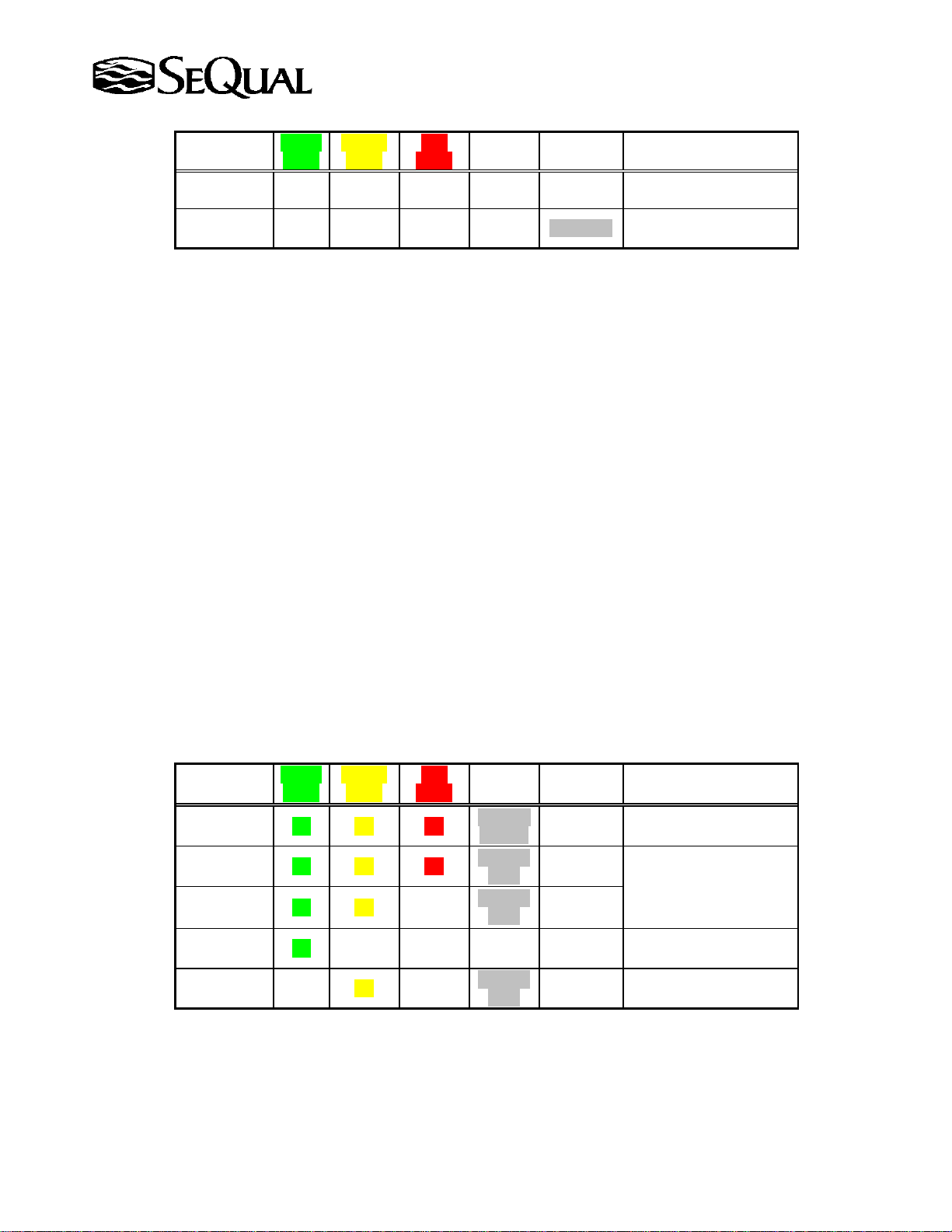
5.1. Alarm Conditions............................................................................................................................................... 15
5.2. Unit fails to start ................................................................................................................................................ 17
5.3. Unit tries to start but shuts down alarming....................................................................................................... 17
5.4. Unit does not produce adequate oxygen flow. ..................................................................................................18
5.5. Unit starts but shuts down after a short period of operation............................................................................18
5.6 Compressor pressure relief valve actuates........................................................................................................18
5.7 Compressor Noisy..............................................................................................................................................19
5.8 Trouble Shooting Guide for Integra E-Z units................................................................................................. 20
6. REPAIR PROCEDURES ............................................................................................................................................23
6.1 Removal and installation of covers ...................................................................................................................23
6.2 Removal and installation of the POD Assembly...............................................................................................23
6.3 Printed Circuit Board Assembly (PCBA) Replacement Procedure.................................................................. 24
6.4 Removal and installation of the ATF module................................................................................................... 26
6.5 Removal and installation of the Compressor Assembly....................................................................................27
6.6 Compressor Top-End rebuild............................................................................................................................ 29
7. INTEGRA E-Z 5L SPECIFICATIONS ..................................................................................................................... 31
8. INTEGRA E-Z 7L SPECIFICATIONS ..................................................................................................................... 32
9. INTEGRA E-Z 10L SPECIFICATIONS ................................................................................................................... 33
10. PART NUMBERS.................................................................................................................................................... 34
10.1. Preventive Maintenance Parts...........................................................................................................................34
10.2. Recommended Spare Parts Inventory...............................................................................................................34
11. SEQUAL ADDRESS AND WEBSITE INFORMATION.....................................................................................35

Service Manual
Integra E-Z Oxygen Concentrators
Chart SeQual Technologies Inc. Page 3 of 34 P/N 2917
1. Introduction
SeQual = Chart SeQual Technologies Inc.
1.1. Explanation of Terms
WARNING:
Indicates the possibility of injury to the patient,
operator, or technician if accompanying procedures
or explanations are not adhered to.
CAUTION:
Indicates the possibility of damage to the device or
equipment if procedures are not followed.
NOTE:
Places emphasis on an operating characteristic or
important consideration.
1.2. Definitions
ATF®(Advanced Technology Fractionator) – The term used to describe the oxygen
concentrating module used in SeQual products.
ESD (Electro-Static Discharge) – The effect of small static electrical charges on printed
circuit boards and components.
LPM (Liters Per Minute) – typically referring to oxygen flow rate
OM (Oxygen Monitor) - Integra concentrators can be ordered with an integrated oxygen
monitor. When specified, a procedure may apply only to OM equipped units.
POD Assembly – Subassembly consisting of the front panel and user interface components
including the printed circuit board and oxygen-monitoring device.
Product/Product flow – Refers to the oxygen being produced.
Rated Flow - The flow rate for which that model of Integra was designed to operate as a
maximum continuous rate. The rated flow of an Integra E-Z 5 is five liters per minute. The
rated flow of an Integra E-Z 7 is seven liters per minute and Integra E-Z 10 is ten liters/minute.
Upgraded – It is the policy of SeQual Technologies to incorporate certain design
improvements into machines, which have been returned to the factory for inspection and/or
repair. References in this manual to serial numbers indicates that the particular feature or
function has been incorporated beginning with that serial number, and is being incorporated on
upgraded machines.
1.3. Introduction to the ATF
The SeQual Advanced Technology Fractionator (ATF®) module eliminates many of the parts found in
conventional pressure swing adsorption oxygen concentrators. It has been designed and constructed to
provide years of trouble free service. A quick inspection will reveal the absence of the product tank,
pressure regulator, and solenoid manifold found in conventional two-bed concentrators. The functions
of these devices are replaced by a single rotating valve, which ports gas movement within the ATF
module.

Service Manual
Integra E-Z Oxygen Concentrators
Chart SeQual Technologies Inc. Page 4 of 34 P/N 2917
The ATF module utilizes twelve sieve beds and a patented rotary valve to produce a constant flow of
oxygen. A small electric motor and reduction gear mounted on the ATF module turns the valve. As the
valve rotates, compressed air is channeled to the beds, resulting in four of the beds producing oxygen,
four beds are static, and four beds are purging. The oxygen is collected in the product head and is then
routed through the pod assembly for patient use. Purge gasses are expelled through two integral
mufflers in the ATF base, characterized by a soft, rhythmic “breathing” noise, which can be heard
when operating the unit with the covers removed.
CAUTION:
There are no field serviceable components in the ATF assembly.
Any attempt to open the module, without the express written
consent of SeQual Technologies, will result in module
contamination and will void the warranty.
The ATF product flow/pressure is self-regulating by matching compressor size (pressure and volume
of flow) to the rated flow of a particular ATF module. Fixed orifices within the module regulate
oxygen used as sieve bed purge gas. No adjustments of any type are required in the field. Full
concentration is usually achieved within three (3) to ten (10) minutes of turning the unit on, therefore a
10-minute warm up period is recommended prior to conducting concentration tests for diagnostic
purposes..
Gas balance is maintained by controlling the flow rate on the POD assembly to operate the unit within
its design range. If the product flow is set beyond this design range, there will be insufficient oxygen
available to completely purge the beds and concentration will drop. Conversely, if there is extremely
low flow (less than 0.5 LPM) more oxygen is purging and a build-up of inert argon gas will occur,
which will reduce overall concentration readings.
As with any mechanical device, certain precautions must be observed in order to maintain the unit
properly. By familiarizing themselves with several basic principles of ATF operation, technicians will
be able to rapidly diagnose problems, effect repairs and return the concentrator to service.
Always apply voltage to the gear motor assembly prior to introducing airflow to the ATF. Check that
the shaft visible on the top of the gearbox is rotating. Some grease run-out in this area is typical,
especially in units that have had long, continuous service. Wipe the area and mark the drive shaft with
a marker to assist in detecting rotation. Minor gear mesh noise is acceptable, but any inconsistent,
jerky, or intermittent motion is not normal. Rotation should be smooth.
Always cap or plug the ATF oxygen outlet and air inlet ports when it is not installed or when the hoses
are removed. Even short duration exposure to moisture-laden air can have an adverse effect on ATF
performance.
Never operate an ATF beyond its rated flow capacity. Ensure that the Integra flow selector knob or an
external flow meter properly limits the product flow rate. An ATF designed to deliver 5 liters per
minute (LPM) of flow will rapidly suffer performance loss if operated at 6 LPM. Within a short period
of time, this performance loss can become permanent.
Never apply compressed air flow to an ATF with a damaged, missing, or malfunctioning gear motor
assembly. Even a few minutes of flow without valve rotation can severely and permanently damage the
module.

Service Manual
Integra E-Z Oxygen Concentrators
Chart SeQual Technologies Inc. Page 5 of 34 P/N 2917
1.4. Basic Mechanical Layout
The Integra E-Z family of oxygen concentrators shares the same basic components and layout,
consisting of the compressor, ATF module, and POD assembly. These components are mounted to the
base and center frame and are housed in a two-piece cover. Although the plastic components are
common to all the Integra E-Z concentrators, refer to the appropriate model data sections concerning
parts replacement.
The Integra E-Z Oxygen Concentrator is manufactured in the following variations:
DESCRIPTION 115V / 60 Hz 220-240V / 50Hz
INTEGRA E-Z 5 LPM 6323A EURO
INTEGRA E-Z 5 LPM OM 6323A-OM EURO
INTEGRA E-Z 7 LPM 6323A-7
INTEGRA E-Z 7 LPM OM 6323A-OM-7
INTEGRA E-Z 10 LPM 6323A-10 6323A-10 EURO
INTEGRA E-Z 10 LPM OM 6323A-OM-10 6323A-OM-10 EURO
User Controls are located on the front panel of the POD assembly. On/Off button, “Plus”(+) and
“Minus”(-) flow rate control buttons, Service button (located behind the No Smoking logo), and the
Flow Indicator LCD display.
1.5. Theory of Operation
1.5.1 Air/Product flow
Ambient air is pulled in through the cabinet inlet filter. A cooling fan in the base expels hot air
through an opening in the bottom of the case. The compressor inlet filter and muffler assembly,
mounted on the center frame above the compressor, provides sound suppression and filtered air
to the compressor via a clear feed tube. Compressed air from the compressor runs through a
heat exchanger coil and into the inlet barb of the ATF module. Oxygen from the product barb is
routed to the pod assembly.
The POD assembly provides electrical power, oxygen flow control, flow rate indication, and
various monitoring functions depending on model. The oxygen outlet port is equipped with a
DISS fitting for connection of appropriate accessories such as a humidifier, cannula, etc.
1.5.2 Electrical
A two-prong plug can be inserted into any standard outlet of the appropriate voltage. All
Integra E-Z concentrators are double insulated and require no grounding.
WARNING
Do not modify or otherwise tamper with the electrical harness or attached
components without the express, written consent of SeQual Technologies. Doing so
could result in the loss of double insulation protection and create a potential hazard.
Line voltage is connected to a printed circuit board mounted in the POD assembly.
Transformers on the board reduce line voltage to low voltage for circuit board control, flow

Service Manual
Integra E-Z Oxygen Concentrators
Chart SeQual Technologies Inc. Page 6 of 34 P/N 2917
control and monitoring functions. Circuit traces route power to the cooling fan, ATF gear
motor, and compressor.
WARNING
Line voltage is present at the circuit board at all times when
the unit is plugged into a wall outlet. Unplug the concentrator
prior to performing maintenance or repairs in this area.
CAUTION:
Do not touch or attempt removal of the circuit board without
ensuring that all Electro-Static Discharge (ESD) procedures
and controls are in place. Damage to components on the printed
circuit board can result in a failure in performance of the device.
The push button On/Off switch is of the momentary contact, which is read by microcontroller
on the main board and turns on the power to activate cooling fan, ATF gear motor and
compressor.. . A Pure Sine wave electrical signal for Mains power is required to operate the
Integra only. Subsequently, a Modified Sine Wave for Mains power is not recommended.
A power management feature has been incorporated to improve protection to the user in the
event of a momentary power failure. In the event of a power interruption, the unit will alarm as
normal for a power loss. A 9V battery provides back-up power for alarm circuit. The unit will
resume operating twenty seconds after the initial interruption, unless it has been turned off
during the power interruption.
Integra E-Z family of oxygen concentrators incorporates a closed-loop feedback flow control
valve, eliminating the need for the user to adjust or tweak the flow on the unit more than the
initial setting. This is accomplished by the integration of a flow and concentration
measurement system (OM models only) in a new control system. From the patient point of
view, the system will operate in a “set and forget” mode where a desired flow rate is set (using
up/down arrows and a display to indicate the target flow rate) and the system automatically
adjusts the internal flow control valve to provide that flow to the patient, regardless of what
accessories are attached to the oxygen concentrator.
The OM models also incorporate circuitry on the printed circuit board which are used in
conjunction with the ultrasonic measurement flow tube and uses the timing of the speed of
sound in the gas mixture to calculate the percentage of oxygen present in the gas stream. A
timing circuit on the board prevents the low oxygen alarm from sounding during the warm-up
cycle (a maximum of 10 minutes).
The Integra E-Z oxygen concentrator does not utilize a conventional circuit breaker. A separate
“current-sense” transformer mounted on the printed circuit board continuously monitors the
current being drawn by the compressor. This sensing feature will turn off the concentrator to
prevent excessive current draw in the event of a component failure or other abnormal high
demand condition. There is nothing to reset. Once the unit detects the abnormal power
condition it will shut-down and alarm. The user will only need to turn off the unit and turn it
back on and assuming the power has returned to normal and there is no additional fault it will

Service Manual
Integra E-Z Oxygen Concentrators
Chart SeQual Technologies Inc. Page 7 of 34 P/N 2917
start running. In addition the Integra E-Z has two fuses. The primary fuse F2 (service
technician replaceable fuse, see Section 10 for spare parts) is used as a back-up to the current-
sensing system and will prevent excessive current draw by the compressor. Another non-
replaceable fuse, F1, provides protection in the event of a transformer failure.
A thermal cut off switch, located in the bottom of the base in front of the compressor, acts as a
thermal circuit interrupt. In the event that the internal cabinet temperature rises above
approximately 140 degrees Fahrenheit (60 degrees C), the switch will open, this will be
detected by the current sense feature and shut the unit off and alarm. The switch will
automatically reset when the cabinet temperature returns to normal operating range. On the
Integra E-Z models once the thermal switch closes again the unit will not automatically turn
back ON after temperature returns to normal. It will require user to address the cause of
overheating (unit covered by blanket or similar issue) and then press the On/Off button to
continue us of the oxygen concentrator.

Service Manual
Integra E-Z Oxygen Concentrators
Chart SeQual Technologies Inc. Page 8 of 34 P/N 2917
2. Set-up and Operation
2.1. The proper location.
Locate the concentrator in a well-ventilated space that provides adequate airflow. Ensure that
furniture, draperies or clothing will not impede air circulation. The Integra requires 6 air
exchanges per hour to properly ventilate. Avoid placing the unit over a floor heat register or
against a baseboard heating system.
2.2. Air intake filter.
The air intake filter should be inspected and cleaned Weekly. It should be clean and free of
debris. Refer to Routine Maintenance Section.
2.3. Control Panel Display
The Control Panel and buttons is shown in the figure below.
2.4. Plug the unit in.
The backlight on the Flow Indicator LCD display will turn ON indicating the unit is energized
and ready for use.
WARNING:
Do Not connect to an extension cord or electrical outlet controlled by a switch. No other appliance
should be plugged into the wall outlet. Voltage requirements are marked on the label on back of unit.
Green Light
On/Off Button
Red Light
Yellow Light
Increase Flow Button
Decrease Flow Button
LCD Flow Indicator
(LPM)
Service Switch
(Hidden Button for
Provider Use Only)

Service Manual
Integra E-Z Oxygen Concentrators
Chart SeQual Technologies Inc. Page 9 of 34 P/N 2917
Flow Rate
Shown?
Green
Light
Yellow
Light
Red
Light
Audible
Alarm
Unit
State
Operating Condition
No Off Off Off Off
Not
Energized
Unit not running / Flow
Indicator Display Not Lit
No Off Off Off Off Energized Unit not running / Flow
Indicator Display Lit
2.5. Starting the Integra E-Z
2.5.1. Push the On/Off button and verify the unit Start-Up Sequence
Allow the unit to warm-up and stabilize (approximately 2 minutes but allow up to 10 minutes).
Adjust the flow using "+" and "−"buttons. A shorter warm-up will occur at lower flow rates.
NOTE:
The Integra E-Z flow indicator sets the target flow rate desired by the patient. The
installation of humidifiers or other devices can cause a back pressure on the unit
therefore it is recommend that the flow rate be set prior to attaching accessories to
the concentrator. After an initial startup or after a power interruption the unit may
automatically reduce the flow rate briefly before returning to the set flow rate.
2.5.2. Start-up Sequence OM units
On initial start-up Integra E-Z units light the Green, Yellow and Red LED’s with a 3 second
beep followed by an intermittent beep for the remainder of the warm-up. As concentration
increases to ~70%, the Red LED turns off and the Yellow and Green remain on. When the
concentration reaches normal operating range (above 85%), the Yellow LED will turn off as
well as the intermittent beep. The Green LED will stay lit indicating normal operation.
2.5.3. Start-up Sequence Non-OM units
On Non-OM start-up Integra E-Z units will light the Green, Yellow and Red LED’s with a 3
second beep indicating all alarms indicators are functioning followed by the green LED turning
on. The table below shows operating conditions for Integra E-Z Oxygen Concentrators:
Flow Rate
Shown? Green
Light Yellow
Light Red
Light Audible
Alarm Unit
State Operating Condition
Yes On On On On for 3
seconds Started
Running Unit is Starting
Yes On On On Periodic
Beep Running Unit is warming up*
Yes On On Off Periodic
Beep Running
Yes On Off Off Off Running Normal Operating
Condition
Yes Off On Off Periodic
Beep Not
Running Unit turned
On/Off/On Quickly
* These conditions are displayed only on units equipped with oxygen monitor.

Service Manual
Integra E-Z Oxygen Concentrators
Chart SeQual Technologies Inc. Page 10 of 34 P/N 2917
2.5.4. Attach required tubing, humidifier and additional accessories as prescribed.
CAUTION:
Use of downstream or external flow control device is not recommended.
The Integra E-Z will attempt to control the flow rate to the target flow
set on the indicator. If the unit cannot control to this flow rate an alarm
indication will occur and potential damage may occur to the unit.
CAUTION:
Use of certain administration accessories not specified for use with
this oxygen concentrator may impair the performance.
2.6. Service Mode:
To Enter Service Mode press the Hidden Switch (located behind the top No-Smoking symbol)
and either the “+” or “-“ button for a minimum of 2 seconds. To Exit Service Mode press the
Hidden Switch and either the “+” or “-“ button again or it will exit by itself after 10 seconds.
2.6.1. Checking Hourmeter (provider use only)
After entering Service Mode use the “+” or “-“ buttons to scroll through the
options until the hourmeter reading is displayed HXXXXX.X
2.6.2. Checking Battery Level (provider use only)
After entering Service Mode use the “+” or “-“ buttons to scroll through the
options until the software revision displayed. 5 Solid Bars = Full Battery and
0 Solid Bars = Depleted Battery. Recommended battery replacement at 2
Solid Bars (See Maintenance Section).
2.6.3. Enable or Disable Battery Level Alarm (provider use only)
After entering Service Mode use the “+” or “-“ buttons to scroll through the
options until the battery symbol is displayed. If the battery alarm is disabled
you will see a “D”, this is how the unit is shipped from the factory. If the
battery alarm is enabled you will see an “E”. To change the alarm status
press only the Hidden Switch while in Service Mode. The Battery Alarm
will be triggered at 2 Solid Bars.
2.6.4. Checking Software Revision (provider use only)
After entering Service Mode use the “+” or “-“ buttons to scroll through the
options until the software revision displayed SW=X.XX

Service Manual
Integra E-Z Oxygen Concentrators
Chart SeQual Technologies Inc. Page 11 of 34 P/N 2917
3. Maintenance
Routine Maintenance: Routine maintenance consists of cleaning the air inlet filter at a weekly interval to keep the
unit functioning properly. Once the filter is cleaned, dried, and re-installed. The user can easily achieve this maintenance.
When other than routine maintenance is needed, contact an Authorized Service Center for a Return Authorization #.
NOTE: Plug the Integra in and run the device for 1 - 2 hours on minimum of a monthly basis.
Annual Maintenance:An Annual Internal Filter PM is required for proper operation of the Integra.
3.1. Cleaning air intake filter
3.1.1 Once a week, the air intake filter located on top of the unit must be cleaned.
3.1.2 Remove the filter from the cabinet.
3.1.3 Wash the filter in warm water using a mild detergent solution.
3.1.4 Rinse the filter thoroughly and squeeze out the excess water.
3.1.5 Allow the filter to air dry.
CAUTION:
The filter should be completely dry before using it again as excess
moisture may impair the proper operation of the oxygen concentrator.
3.1.5 Re-insert the filter in the cabinet.
CAUTION:
The air intake filter should be replaced Annually. If the Oxygen
Concentrator is used in a dusty environment, the filter may need to
be cleaned or replaced more often. Do Not operate the Oxygen
Concentrator for more than 30 minutes without a filter installed

Service Manual
Integra E-Z Oxygen Concentrators
Chart SeQual Technologies Inc. Page 12 of 34 P/N 2917
3.2. Scheduled Preventive Maintenance (Use PN 4542-SEQ “Annual PM Kit”-
once every 12 Months(Annually) or as needed)
3.2.1. Replace the 9V Battery once every 12 Months(Annually) or when Battery Level is at 2
Bars: Replace the 9V battery(8098-SEQ) annually or when the Battery Indicator
Level is at 2 Bars. To check this, enter Service Mode as described in Section
2.6.
3.2.2. Replace the Compressor Inlet Filter once every 12 months(Annually) or as needed:
Replace the compressor intake filter annually or as needed
depending upon the environment in which the concentrator is
operating. The compressor intake filter can become clogged
depending upon the amount of contaminants in the air (smoke,
dust, dirt, pollen, etc.) and may need to be changed more
frequently. Refer to the Troubleshooting Guide for signs of a
clogged filter and refer to the Replacement Parts section for the
correct compressor intake filter.
CAUTION:
Operation of the oxygen concentrator with a clogged compressor
intake filter will reduce the performance of the unit and can lead to
system damage and premature failure.
3.2.2.1.Open the hook and loop straps holding the Filter on the Filter/Muffler assembly. Hold the unit
and twist and pull the filter to remove it from the muffler. Insert outlet tube on Filter (2607-
SEQ) into the hole on the Muffler. Rotate the filter so that the two parts are lined up across the
top length and side. Firmly push the Filter into the Muffler until the two parts touch, and re-
secure the velcro loop strap.
3.2.2.2. In addition ensure the free end of the PVC Tubing is on the compressor Air Inlet Fitting barb.
NOTE:
The most common cause of
low concentration and eventual
system failure is a dirty or
clogged compressor inlet filter.
The environmental conditions
in which the unit is operated
determine the effective filter
life.
Muffler
Attached to
Center Frame
Loop Strap securing
filter to muffler
PVC Tubing
attached to
Muffler
REPLACE
FILTER

Service Manual
Integra E-Z Oxygen Concentrators
Chart SeQual Technologies Inc. Page 13 of 34 P/N 2917
3.2.2.3.Verify proper oxygen concentration(refer to spec chart pg# 31, 32, or 33). The concentration
should be a minimum of 88% at maximum rated flow. Refer to the troubleshooting section if
this concentration is not met. While monitoring the concentration, verify that the LED’s
function properly on OM equipped units during start-up.
3.2.2.4.Clean inside the unit, as needed using a small vacuum cleaner to remove any accumulation of
dust or debris, prior to attaching the covers.
3.2.3 Replace the HEPA filter once every 12 months(Annually) or when visibly dirty.
3.2.3.1 Remove the existing clamp or cut off the existing cable tie on one side of the HEPA filter.
3.2.3.2 Disconnect tubing from both sides of HEPA filter.
3.2.3.3 Plug in new HEPA filter.
Note: If new HEPA filter still shows IN on input, and OUT on output, or an arrow shows
direction of the flow, make sure that HEPA Filter is installed following the direction of the
flow, which is from the ATF to the POD. Flow is upwards in the picture below.
3.2.3.4 Apply a new cable tie or clamp around the tubing.
4. Test Procedures
4.1. Unit Test Procedure - Preferred Method
It is recommended that the Integra E-Z be tested for oxygen concentration and flow
performance periodically. The factory recommended Test Setup for the Integra E-Z is shown
on the following diagram. Oxygen monitors may or may not have an internal pump to draw
samples of Oxygen to be measured. Placement of the Oxygen Monitor in the test circuit
depends whether they have an internal pump. Only one Oxygen Monitor is needed though.
4.1.1 Connect the circuit per the diagram shown on the next page.
4.1.2 Turn the concentrator on and allow it to warm up at one-half of its rated flow setting
(approximately 5 minutes).
4.1.3 Set the target flow on the Integra E-Z to the maximum rated flow, 5 LPM for Integra Five, 7
LPM for Integra Seven, 10 LPM for Integra Ten and oxygen monitor flow valve to low flow
settings.
4.1.5 Allow the unit stabilize (approximately 10 minutes).
HEPA filter

Service Manual
Integra E-Z Oxygen Concentrators
Chart SeQual Technologies Inc. Page 14 of 34 P/N 2917
4.1.6 Verify the O2 concentration, O2 flow rate and O2 pressure are within specification (See Section
7, 8 or 9 depending on the model).
Factory Recommended Test Setup to verify performance of Oxygen Concentrator
NOTE:
For Integra E-Z units an external flow valve will not perform
adequately due to the flow control circuit. In this situation the
pressure gage should be plumbed into the system at the HEPA filter,
inside the unit. For the O2monitor without pump, it can be installed
after the outlet of the external flow meter or at the outlet fitting (see
Alternate Method 4.2) to force the O2gas through the O2analyzer
(check to ensure the O2 analyzer can handle the total flow rate).
4.2. Unit Test Procedure-Alternate Method
Attach a calibrated Oxygen Monitor to the DISS block in accordance with Oxygen Monitor
manufacturers recommendations. It is important to not obstruct the flow, as this will affect the
Integra’s actual concentration (lower flow will typically increase the oxygen concentration)
NOTE:
The flow control circuit on the Integra E-Z is designed to properly
deliver oxygen flow rates during normal usage. Some sensing
equipment may restrict the actual flow rate below what the Integra
E-Z can provide and provide inaccurate concentration readings. A
highly blocked oxygen outlet will result in lower oxygen
concentration due to a build-up of argon gas.
4.3. Alarm Verification Test
Verify the Alarm Indicators (buzzer and lights) are functioning properly by confirming the
proper start-up sequence for the unit per sections describe below.
4.3.1. Start-up Sequence OM units
On initial start-up Integra E-Z units light the Green, Yellow and Red LED’s with a 3 second
beep followed by an intermittent beep for the remainder of the warm-up. As concentration
increases to ~70%, the Red LED turns off and the Yellow and Green remain on. When the
concentration reaches normal operating range (above 85%), the Yellow LED will turn off as
well as the intermittent beep. The Green LED will stay lit indicating normal operation. The
INTEGRA E-Z
INTERNAL
FLOW
CONTROL
VALVE
FLOW
METER
O
2
MONITOR
WITH PUMP
(Preferred Location)
PRESSURE
GAUGE
O2MONITOR
WITHOUT PUMP
(Alternate Location)
Atmosphere

Service Manual
Integra E-Z Oxygen Concentrators
Chart SeQual Technologies Inc. Page 15 of 34 P/N 2917
table on the next page shows the normal start-up operating conditions for Integra E-Z Oxygen
Concentrators.
4.3.2. Start-up Sequence Non-OM units
Non-OM Integra E-Z units start-up with the Green, Yellow and Red LED’s lit and a 3 second
beep indicating all alarms indicators are functioning followed by the green LED turning on.
The table below shows the normal start-up operating conditions for Integra E-Z Concentrators.
Flow Rate
Shown? Green
Light Yellow
Light Red
Light Audible
Alarm Unit
State Operating Condition
Yes On On On On for 3
seconds Started
Running Unit is Starting
Yes On On On Periodic
Beep Running Unit is warming up*
Yes On On Off Periodic
Beep Running
Yes On Off Off Off Running Normal Operating
Condition
Yes Off On Off Periodic
Beep Not
Running Unit turned
On/Off/On Quickly
* These conditions are displayed only on units equipped with oxygen monitor.
5. Troubleshooting
5.1. Alarm Conditions
Flow Rate
Shown?
Green
Light
Yellow
Light
Red
Light
Audible
Alarm
Unit
State
Operating Condition
Yes Off Flashing Off Off Running
Oxygen Concentration
Below Normal Level *
O
2
Flow Rate Not Correct
10% off target flow
Yes Off Off Flashing On Running
Oxygen Concentration
Abnormal Level *
1
O
2
Flow Rate Abnormal
30% off target flow1
Yes Off On Off Off Running Button Stuck
Yes On On Off Off Running
9V Battery Low Voltage
(if enabled)
No Off Off Flashing On Not
Running
Unit is overheating
Compressor Malfunction
Power Interruption
No
On or
Off
On or
Off
On On Running System Malfunction1,2
* These conditions are displayed only on units equipped with oxygen monitor.
1Call the SeQual Customer Service if abnormal conditions are detected and cannot be remedied.

Service Manual
Integra E-Z Oxygen Concentrators
Chart SeQual Technologies Inc. Page 16 of 34 P/N 2917
2During System Malfunction condition the Green and Yellow lights may be On or Off.
5.1.1 Flashing RED LED, Steady alarm sounding.
5.1.1.1.Power Interruption External to Unit - Current from wall outlet interrupted. Push the On/Off
button to stop alarm. Check for open household fuse or actuated household circuit breaker.
Restore power.
5.1.1.2.Power Interruption Internal to Unit - Thermal switch activated. Push the On/Off button to stop
alarm. Check for adequate clearance (refer to the Operation and Set-up section).
5.1.1.3.Power Interruption Internal to Unit – Compressor Malfunction (See Section 5.5 or 5.9 for
compressor troubleshooting).
5.1.1.4.Power Sags and Surges – Simulating a circuit breaker popped due to a high or low current.
Correct the source of the power problem. Push the On/Off button to stop alarm (the unit resets
itself if the source of the inconsistent power is resolved). Wait for at least 20 seconds and push
Off/On button to restart the Integra E-Z.
5.1.1.5.Oxygen flow rate being measure and controlled by the Integra E-Z doesn’t agree with flow set
on the front panel by more or less than 30% of target flow rate. If alarm persists, check for
kinked or blocked tubing inside or outside the unit, or for leaks between the flow meter and the
control valve. For further investigation check to see if the flow control valve is stuck in the
open or closed position, or doesn’t adjust the flow.
5.1.2. Solid YELLOW LED, No alarm
5.1.2.1.The concentrator has detected a stuck button. The button determined to be stuck will not
function. To locate which button is stuck push the buttons one at a time and see which one does
not react. If the On/Off button is stuck unplug the power cord from the wall to turn the unit off.
5.1.3. YELLOW and GREEN LED Illuminated Only, No alarm.
5.1.3.1.The concentrator is indicating that the 9V Battery has a low voltage level. This is signaling the
technician or patient that the Battery Level is at 2 Bars and the battery needs to be replaced.
NOTE:
This Alarm Indicator is shipped from the factory as “D” Disabled. The
provider may chose to turn this feature on as described in the Service
Mode Section 2.6.3, and if this feature is disabled and the battery is
drained the unit will not be able to alarm in the event of a power failure.
5.1.4. Flashing YELLOW LED, No alarm.
5.1.4.1.Oxygen flow rate being measured and controlled by the Integra E-Z doesn’t agree with flow set
on the front panel by more than 10%.. If alarm persists, check for kinked or blocked tubing
inside or outside the unit, or for leaks between the flow meter and the control valve. For further
investigation check to see if the flow control valve is stuck in the open or closed position, or
doesn’t adjust the flow.
5.1.5. OM Models - YELLOW LED illuminated. Concentration is below 85%
5.1.5.1.Check flow rate setting - flow set too high will reduce concentration. Allow 5 minutes for flow
to stabilize at lower setting, green LED should illuminate.
5.1.5.2.Filter clog- check cabinet inlet filter and compressor inlet filter (refer to Routine Maintenance
section).

Service Manual
Integra E-Z Oxygen Concentrators
Chart SeQual Technologies Inc. Page 17 of 34 P/N 2917
5.1.5.3.Unit out of calibration- perform concentration check.
5.1.5.4.Unit overheating- efficiency of the adsorption process is reduced if cabinet temperatures are
elevated. Ensure adequate ventilation (refer to the Operation and Set-up section)
5.1.5.5.Compressor worn - check compressor output.
5.1.5.6.ATF worn – check unit with another equivalent ATF.
5.1.6. OM Models - Red LED Flashing, Steady alarm. Concentration below 70%
5.1.6.1.Push the On/Off switch to silence alarm. Attempt restart and check for the same conditions as
outlined above (flow setting, filter clog, etc).
5.1.6.2.Check the unit interior for loose or disconnected oxygen tubing.
5.1.6.3.Disconnect external attachments and run Integra. Check for fluctuations (+1 LPM). If
fluctuations present, contact SeQual Customer Service.
NOTE:
On initial start-up, a timing circuit in the printed circuit board prevents the
alarm from sounding while the unit stabilizes. The alarm will not sound
until this 10 minute warm-up time delay is complete. During this time an
intermittent beep will sound alerting the user that the Integra E-Z is
warming up.
5.2. Unit fails to start NOTE:
All Integra E-Z models contain a power management feature that will
automatically restart a unit that experiences a power interruption. If the
power interruption was very short and the unit was not turned off or the
unit was turned off and on quickly - there will be a delay in starting. The
Yellow Indicator light will be on and an intermittent beeping sound will be
heard. Wait 20 seconds. Unit will start automatically.
5.2.1. If unit doesn’t start, first check if Flow Indicator (LCD Display) backlight is turned on (in
bright daylight this may be a little difficult to detect so cup your hand around the display area to
determine if this light is on). If it is off follow next steps.
5.2.2. Check that unit is plugged in.
5.2.3. Check that the unit is not plugged into an outlet controlled by a wall switch that is off.
5.2.4. Check that the fuse or circuit breaker controlling the outlet is intact/on.
5.2.5. Check the main fuse on the circuit board is not blown. Replace this fuse if it is blown.
5.2.6. Check the compressor capacitor is not shorted or blown. Replace if needed.
5.3. Unit tries to start but shuts down alarming
NOTE:
A unit which has been exposed to temperatures below 50ºF for an extended
time may have cold-soaked the compressor piston sleeves, causing the
sleeves to contract. This will be indicated by a squealing sound or failure of

Service Manual
Integra E-Z Oxygen Concentrators
Chart SeQual Technologies Inc. Page 18 of 34 P/N 2917
the compressor to start. Allow the unit to come up to room temperature
before operating.
5.3.1. Attempting to start the unit with air pressure already in the system will cause the compressor to
stall. As stated in the Note in section 5.2 a time delay feature has been added to prevent the unit
from starting until the pressure in the system has bled down.
5.3.2. Unplug unit, open covers and check to ensure the compressor can be rotated by turning the fan
by hand. If this is difficult to do then there is a compressor malfunction and the compressor
must be serviced or replaced.
Warning: Ensure the unit is unplugged before testing this operation.
Warning: Use a glove or similar hand protection to rotate the fan, the plastic edges can
be sharp and cut your hand.
5.3.3. Check for damage to the traces on the circuit board. Failure of an internal component can
cause excessive power draw. This will typically result in burn marks adjacent to the eight-pin
connector that can be observed with the back cover removed. Contact SeQual Customer
Service for assistance.
5.4. Unit does not produce adequate oxygen flow
5.4.1. Check to verify that the target flow set point is correct
5.4.2. Check for a blocked humidifier bottle (if one is being used). Tip: Remove for testing.
5.4.3. Check for external kinked, flattened, or blocked tubing or accessories (remove accessories from
DISS fitting and see if adequate flow is coming out of the DISS fitting).
5.4.4. Remove covers and check for internal kinked, flattened, or blocked tubing.
5.4.5. Check the inside of the unit for loose or disconnected tubing.
5.4.6. Check for operation of the flow control valve (open and close the valve by pushing the “+” and
“-“ buttons and look for or feel the valve moving/stepping).
5.4.7. Check for air flow blockage in elbow-muffler connection. Replace muffler if necessary.
5.5. Unit starts but shuts down after a short period of operation
5.5.1. Re-start the unit and check for adequate airflow (refer to Operation and Set-up).
5.5.2. Check for cooling fan operation. Air should be blowing out of the bottom of the cabinet and
can be felt by putting a hand under the base. If no Air flow is present:
5.5.3. Unplug the unit, remove the covers and check cooling fan for blockage. Plug the unit back in
and check for line voltage at the fan connector. If not present, check to ensure the eight-pin
connector (J10) is securely connected at the printed circuit board. If the connection is “good”,
then replacement of the printed circuit board or POD assembly may be required. Contact
SeQual Customer Service for assistance.
5.6. Compressor pressure relief valve actuates
5.6.1 Turn unit ON and check for valve rotation on the ATF. Loosen the four clamp screws attaching
the ATF to the base, sufficiently to lift the ATF out of the nest to rotate the ATF onto its side
being careful not to hit the gearmotor on the base. It is not necessary to remove any tubing or
hoses. Lay the ATF on its side on the base and look at the gearbox for the drive shaft rotation.
NOTE:

Service Manual
Integra E-Z Oxygen Concentrators
Chart SeQual Technologies Inc. Page 19 of 34 P/N 2917
Drive shaft rotation may be difficult to see.
Mark the shaft using a sharpie marker or grease pencil.
5.6.2 If the valve is rotating smoothly, test the compressor relief valve (See step 6).
5.6.3 If the valve motion is jerky, hesitates, or otherwise displays inconsistent rotation, replace the
ATF.
5.6.4 If there is no valve rotation, check for AC line voltage on the two-pin connector to the gear
motor. If voltage is present, replace the ATF.
5.6.5 5.8.5 If no voltage is present, check for loose connections on the eight-pin connector on the
PCA board. If continuity check in the harness doesn’t detect bad contact, replace the pod or
PCA board assembly.
5.6.6 5.8.6 To test the compressor pressure relief valve (PRV) the ATF will need to be
disconnected from the compressor:
5.6.7 Remove the air tube from the air inlet barb on the ATF and attach to the following gauge setup.
5.6.8 Install a “T” fitting to the hose from the compressor. At one end of the “T” install a pressure
gauge, at the other end install a needle valve (fully open) in series with a flow meter.
5.6.9 Start the compressor and slowly increase the pressure by closing the valve. The pressure relief
valve should not actuate until 35 (+2) psig.
5.6.10 Cycle the PRV a few times to clean out any potential contamination. Test the PRV again to see
if it activates at 35 (+2) psig. Replace if it fails.
5.6.11 If these steps do not identify the problem, contact SeQual Customer Service for assistance.
5.7. Compressor Noisy
5.7.1. Compressor noises can be either a result of vibration being transmitted to the frame or a sign of
impending compressor failure. Bearing or piston noise can be localized by holding a long
screwdriver on the compressor frame or head while placing your ear against the handle. Noise
of this type will not be repairable by rebuilding the compressor; it will need to be replaced.
NOTE:
A unit which has been exposed to temperatures below 50ºF for an
extended time may have cold-soaked the compressor piston sleeves,
causing the sleeves to contract. This will be indicated by a squealing
sound or failure of the compressor to start. Allow the unit to come up
to room temperature before operating.
5.7.2. Noise as a result of vibration transmission can occur if the heat exchanger coil has been
deformed due to rough handling. Improper coil spacing can pre-load the compressor spring
mounts, transmitting compressor vibration to the frame.
5.7.3. Remove the covers and start the unit.
5.7.4. Press on the right end of the compressor to see if noise abates.
WARNING:
There are no fan guards on the compressor. Keep fingers clear
of the fan blades!
WARNING:

Service Manual
Integra E-Z Oxygen Concentrators
Chart SeQual Technologies Inc. Page 20 of 34 P/N 2917
If the compressor has been running for any length of time, the
compressor surfaces (especially the metal ones) will be hot and can
cause burns. Wear protective gloves as required.
5.7.5. If the noise does not go away or increases, gently press on the left end of the compressor.
5.7.6. If the noise persists, check for loose hardware. Refer to the Compressor Installation section.
5.7.7. If the noise goes away while pressing on one of the compressor ends, the heat exchanger coil
will need to be reshaped. If the noise decreased while pressing on the right end, the coil needs
to be closed slightly. If the noise decreased while pressing on the left end it will need to be
opened slightly. WARNING:
Do not perform this with bare hands and a unit, which has been
running for any period of time. The heat exchanger becomes very
hot and can cause bad burns to hands. Wear protective gloves as
required.
5.7.8. Open or close the coils by gently manipulating with thumbs and fingers. The spacing between
the coils should be even. Ensure that none of the coils contact each other. Ensure that the air
hose running through the center frame does not touch the sides of the opening.
5.7.9. If the noise occurs after the compressor has been removed from the unit and or rebuilt the
vibration isolation springs may be forcing the compressor out of its natural position. To remedy
this issue look at one end of the compressor and see if it is leaning toward or away from center
frame. Rotate the springs to bring the compressor into a neutral position. This will need to be
done for all four springs as well as in conjunction with the reshaping the heat exchanger.
NOTE:
A noise free installation requires the compressor to sit on the four
springs in a neutral position without any external force pushing it out
of position.
5.8. Trouble Shooting Guide for Integra E-Z units
Table 1: Concentrator is not Running
Symptom
Probable Cause
Remedy
Unit won’t start
Flow Indicator Blank
Back Light Off
Power cord not plugged into wall outlet. Check condition of power cord.
Plug in power cord.
Internal Fuse blown.
Check condition of power cord.
Service required.
Audible Alarm
Blinking Red Light
Flow Indicator Blank
Back Light Off
Power cord pulled from wall outlet. Plug in power cord.
Power outage.
Push On/Off Button to turn off
unit.
Push On/Off Button to restart unit
when power comes back on.
This manual suits for next models
12
Table of contents
Other SeQual Medical Equipment manuals