Serenity SSE-1 User manual


Floor Model Options
Tools Required:
Tape Measure, Screw Gun, Level, Pencil, 1/2” Socket Wrench and Silicone.
*All hardware for shower parts are included in each part box. #2 Square tip bit is included in door
hardware box.*
You will need to purchase the necessary screws/bolts to mount unit to the ground.
- If placing shower on Pavers, Cement or Blacktop: you will need 2” X ¼” Simpson Strong Tie “Titan” or
equivalent masonry anchor, washers and a ¼” masonry drill bit (6 screws for a double unit and 4 screws for a
single unit).
- If placing your shower on Gravel, Grass or Dirt:you will need 4” x 3/8” lag bolts (Qty. 6 for double 4 for
single). With this application we recommend that you use a pressure treated wooden base. See Below….
*Set chuck on drill to a low speed when installing screws. Higher speeds will break screw.
Single Models Size: 46”d x 46”w x 88”h, 36”d x 36”w x 88”h - 89 1/2”h with roof
Model SSE-1
Model SSE-2
Double Models Size: 46”d x 88”w x 88”h, 36”d x 68”w x 88”h –89 ½”h with roof
Model DSE-1
Model DSE-2
Model DSE-3
Model DSE-5
Model DSE-6
Model DSE-7
Model DSE-4
Model DSE-8

For soft ground surfaces, the unit must be secured to a base placed in the ground. The base will be filled with
pea gravel to create a French drain under the flooring.
2x6 Base: You will need the following materials to create the base:
Double 46" Base
Double 36" Base
4 - 80" 2x6 Pressure Treated Wood
4 - 60" 2x6 Pressure Treated Wood
4 - 38" 2x6 Pressure Treated Wood
4 - 28" 2x6 Pressure Treated Wood
6 - 24" 2x6 Pressure Treated Wood
6 - 20" 2x6 Pressure Treated Wood
10 - Bags of Pea Gravel
8 - Bags of pea gravel
Single 46" Base
Single 36" Base
8 - 38" 2x6 Pressure Treated Wood
8 - 28" 2x6 Pressure Treated Wood
4 - 24" 2x6 Pressure Treated Wood
4 - 20" 2x6 Pressure Treated Wood
5 - Bags of pea gravel 4 - Bags of pea gravel
Notch the wood together as pictured to create the base. Secure the wood in all four corners using galvanized
or stainless steel nails 6” in length. Dig a hole the size of the unit you are assembling into the ground and place
the wood frame into the ground making sure it is level (using standard level) on all four sides. Dig a deeper
cone shape hole in the middle for better drainage and insert pea gravel until the frame is full. This will allow
for better drainage of the water.
PLEASE NOTE* - Unit will overhang on all four sides when installing it to the wood for future pavers or tuck
stone or dirt underneath. For pavers being installed around the shower do not dig the wood base in the
ground so it is level lift the base up 2 to 3 inches to leave room so the pavers can tuck underneath.

1.) Setting Frame (s):
a. Remove the base frame from the box and lay on a flat surface
where the shower unit will be installed. PIC 1a
b. For double units make sure the center supports of both
frames are in line with each other then fasten using Qty. (4)
¾” self-tapping screws for 46” units and (3) ¾” self-tapping
screws for 36” units. PIC 1b
c. If you are installing a Cabana unit follow step 1b to install the additional frame.
*Before moving to the next step it is important to determine your door location and swing.
2.) Setting Posts:
a. Remove one set of posts from the post box and place on the frame where you have determined you
want the door to be. * The elongated holes at the base of the post must be parallel with the shower
door opening. PIC 2a The post flange will already be attached to the post. Lift the flange to access
where post bolts secure to base frame WITHOUT removing flange from post.
b. Using the 5/16” x 3/4”stainless steel bolts provided (4 per post) secure post to frame by screwing in
bolts halfway. *Do NOT over tighten!
Allow room to move the post slightly this is important to be able to set the wall panels. PIC 2b
c. Continue with steps a & b until all posts are attached to the base frame.
PIC 1a
PIC 4a
PIC 1b
PIC 4a
PIC 2a
PIC 4a
PIC 2b
PIC 4a

3.) Installing Wall Panels and Post Bracket: (Make sure speed on drill is adjusted to a low speed)
*If you purchased a Shower Valve Trim Set with removable wall panel put this aside and it will be the last panel you
install. See Step 4 below for instructions.
a. On the face of the post where the wall/header will sit, place the post bracket jig on top of post (post bracket jig is
found in the base frame box). PIC 3a *Important: This will keep header and top of the wall panel aligned. *
b. Place post bracket inside jig. Attach the bracket using the self-tapping ¾” stainless steel screw (provided in wall
panel box). PIC 3b
c. Measure down from the TOP of the post bracket 72 1/2” and make a mark. Above that line measure in 1” from
the side of the post and make another mark forming an upside down “T”. PIC 3c
d. Align the bottom of the post bracket with the bottom line of the upside down “T” and center the post bracket
screw hole with the center of the upside down “T”. Attach the bracket using the self-tapping ¾” stainless steel
screw (provided in wall panel box). PIC 3d
e. Repeat steps 3a thru 3d on adjacent post where wall panel will be installed.PICc
f. Leaving the plastic on the wall panel, set the panel into the bottom brackets first, and then pull the posts away at
the top. The top of the wall panel should fit snug into the post brackets. If the wall panel does not clear the top
panel bracket and fit snug loosen the post bolts (Previous PIC 2b) to adjust. PIC 3f
g. Fasten the wall panel to the brackets using the self-tapping ¾” stainless steel screws on all four corners of the wall
panel. *All screws must be facing the interior of the shower & centered on bracket. PIC 3g Continue this process
until all wall panels are installed.
h. For open walls, a header will be provided in its own separate box in order for you to secure the two posts together.
Follow steps 3a & 3b to attach the post brackets. (OPEN SIDE UP) PIC 3h
i. There will be another header provided in its own separate box to be installed from post to post where the door will
be going. Follow steps 3a & 3b to install it. (OPEN SIDE UP)
j. Tighten the bottom bolts of each post to secure the unit. The post must be tightened evenly to
ensure unit will be level.
PIC 1b
PIC 3c
PIC 2d
PIC 3d
PIC 3a
PIC 3b
PIC 3g
PIC 3f
PIC 3b
PIC 3c
PIC 3h
4.) Outdoor Shower Trim Set Panel Installation:
a. Install a header from post to post following the same instructions in 3a & 3b (PIC 3H)where the
removable panel will go. Install another post bracket directly under the two supporting the header as
you see in PIC 4a
b. Follow instructions from previous Steps 3c & 3d above to measure for the post bracket at the bottom of
post where panel will be installed. Make sure you measure from the top post bracket.
c. Install special cut post bracket (2-Sided) included in box of the removable panel as per the same Steps 3c
& 3d with the opening facing the interior of the unit. PIC 4c
d. Repeat on adjacent post.
e. Install the panel by placing the top in first and set bottom on special post brackets.
f. Drill ¼” hole on bottom of the panel and through post bracket to install clevis pins. Repeat for adjacent
side. PIC 4f
5.) Installing Half Wall Panel (Double Units):
a. Install a header from post to post following the same instructions in 3a & 3b.
*Important when installing the header, the OPEN SIDE IS DOWN THIS TIME.
b. On the post where the ½ wall panel will be installed, measure down from the
TOP of the post bracket 72 1/2” and make a mark. Above that line measure in
1” from the side of the post and make another mark forming an upside down
“T”. ( PIC 3c)
c. Place the half wall panel into the header beginning on the end with
no U-channel. The side with the u-channel should face towards the center of the unit.PIC 5a
d. Install a self-tapping screw through post bracket on the top and the bottom of the wall panel side
attaching to the post through the post bracket. See previous PIC 3g
6.) Secure Shower Unit to Surface
Before screwing down the frame, use plastic washers or PVC shims to level frame.
*The frame must be level prior to fastening*.
a. If you are placing your shower enclosure on a solid surface like; pavers, concrete or blacktop; attach the
frame to a level surface using 2” x ¼” Simpson Strong Tie “Titan” Screws. You will need 6 screws for a
double unit and 4 screws for a single unit. Plastic shims are recommended to avoid contact.
b. If placing your shower on the Base as described in the beginning of the install manual; attach the frame
using 4” x 3/8” lag bolts. You will need 6 qty. for a double unit and 4 qty. for a single unit.
PIC 5c
PIC 4f
PIC 4c
PIC 4a

7.) Installing Shower Door:
*Note: For DSE-7, 8 and CSE 9 & 10 Models –Door swing must be in the same direction for Handle to Align
Properly. Make sure the unit is secured to the surface and level so the door sits plumb. Determine your
door swing prior to moving on. All screws for the door are included in the door hardware box.
a. Follow steps from PIC 2a & 2b to install the header if you have
not done so already.
b. On the post where the hinge will go place the door jig
(found in base frame box) with lip on the inside of the post
and draw three to four separate marks going down the side
of the post. PIC 7b
*Important: This will ensure the hinge is secured straight
on the post.*
c. Find the door hanger in the door hardware box and install it on the top
corner of the hinge side PIC 7c
d. Hang the door so that the door hanger is on the top of post that the
hinge will be installed too. The hinge pin must be on the outside of the
unit on so that the door will open properly PIC 7d
e. Open the hinge and align the holes with the lines that were drawn in Step b.
f. Using the self-tapping stainless-steel screws, start at the bottom and attach the hinge to the post by
working your way up. PIC 7f
*The bottom of the door must align with the bottom of adjacent wall panels.
PIC 7c
PIC 7d
PIC 7f
PIC 7b

8. Installing the Lock: Go to YouTube for a video of installing the lock…”SerenityEnclosureLockInstallation”
•Be sure the drill is on a low speed.
Remove the lock from the door hardware box and ensure deadbolt is in the closed position. *Important*
a. Separate the door lock and spacers with the flat side facing you as you see in PIC 8a(1) & 8a(2).
b. Flip the spacers over and secure to each corresponding side as you see in PIC 8b(1) & 8b(2).
(Once secured the side facing you should have the notches in it).
c. As you are standing on the outside of the door insert the side of the lock with the keyhole into the
opening of the door. Be sure to hold the handle in the open position as you are doing it. PIC 8c
d. Once attached secure the lock to the door by using the two smaller ¼” stainless steel screws
provided in the bag of screws (Qty.6 2 small & 4 larger) found in the door hardware box. PIC 8-d.
e. Once the screws are secured put the door bolt side on. Use the four larger3/4”stainless steel screws
to secure the lock. PIC 8e.
f. Hold the door in the closed position and mark the proper location to attach the strike plate by
aligning the plate with the lock so it is centered.
g. Attach the strike plate using the white self-tapping ¾” stainless steel screws. Make sure edge is flush
with front edge of post and the beveled edge is on the outside so the door closes properly. PIC 8g
h. Align the door stop behind the strike plate by marking out the center of the door stop with a ruler
and making sure the center hole of door stop aligns with the middle of the strike plate PIC 8h.
i. Once in place use the white ¾” self-tapping screws to secure the door stop. Then complete the
installation by placing two of those same screws spaced equally apart on the top of the center screw
and on the bottom of it.
PIC 8a (1)
PIC 8a (2)
PIC 8b (1)
PIC 8b (2)
PIC 8c
PIC 8d
PIC 8e
PIC 8g
PIC 8h

*IMPORTANT: YOU ARE READY TO ADJUST POSTS FOR EQUAL REVEAL AND TIGHTEN THE POST BOLTS SECURELY TO
THE FRAME
9.) Installing the Roof:
*2 people are recommended for this step. If unit is being
Installed against a structure, install post caps prior to
Installing roof. See Step 12.*
a. Assemble the roof on the ground by separating the pickets
(shorter pieces) from the rails (longer louver pieces). Place the
End pieces on the ground with slats going in the same direction.
PIC 9a (1) & 9a (2).*For privacy purposes determine the direction you would
like the louvers to go prior to sliding them on.
b. Insert the rails into the one end of the pickets until all rails are secured by
snapping them in. Then install middle pickets (how many pickets you have is
determined on size of the model you received). Total pickets with end pieces
include: Single 46” – 4 pickets, Single 36” - 3 pickets, Double 46” & 36” - 6
pickets. Once all middle pickets are in place snap in the end picket. PIC 9b
c. Install the flat caps to the side of the roof that will be on the back of the
shower enclosure by using silicone to secure them. PIC 9c
d. With one person standing inside the shower to guide and support the roof, lift the roof and slide it into
place. (For double enclosures make sure you have 3 pickets on either side of the middle post before
moving on). The back of the pickets should be flush with the base frame before proceeding. The end
cross beams should sit just inside your top wall brackets. PIC 9d
e. Space pickets evenly with roof jig (provided with installation kit). PIC 9e
f. Use the L brackets and self-tapping ¾” stainless steel screws to attach each cross beam to the inside of a
wall panel or header on both the front and rear of the shower.PIC 9f
g. Install the pergola end caps by using silicone to secure them to the pickets that are in the front of the
unit.
h. It is time to secure the peek a boo bracket on either side of the roof. Place the drilled holes
against the end pickets. Center it to where it should be (approximately 5” on either side).
Use self-tapping ¾” stainless steel screws in the pre-drilled holes to secure the peek a
boo bracket to the louvered roof. PIC 9h
PIC 9c
PIC 9a (1)
PIC 9a (2)
PIC 9b
PIC 9d
PIC 9f
PIC 9e
PIC 9h

10.)Installing the Towel Bar/Hook Bar: *Note: You can install the towel and hook bar wherever desired on the
inside or outside of the unit.…Standard install is as follows:
a. Towel Bar: Measure 54” off finished floor and mark 2 adjacent posts (the desired
Posts on the side where the towel bar will be placed).
Use self-tapping ¾” stainless steel screws provided. PIC 10a
b. Hook bar should be installed at the same height as
The top of door hinge PIC 10b
11.)Installing the Floor:
a. For a single base frame start at either edge of the frame, lay one of the pre-assembled floor panels in
place; followed by the matching interlocking panel. Note the floor planks should run perpendicular to
the frame joists. PIC 11a
b. For the expander frame the floor panel with the smaller plank is to go on the side away from the single
base floor with the floor planks perpendicular to the frame joists. Install the remaining floor panel in the
open space next to the single base floor frame.
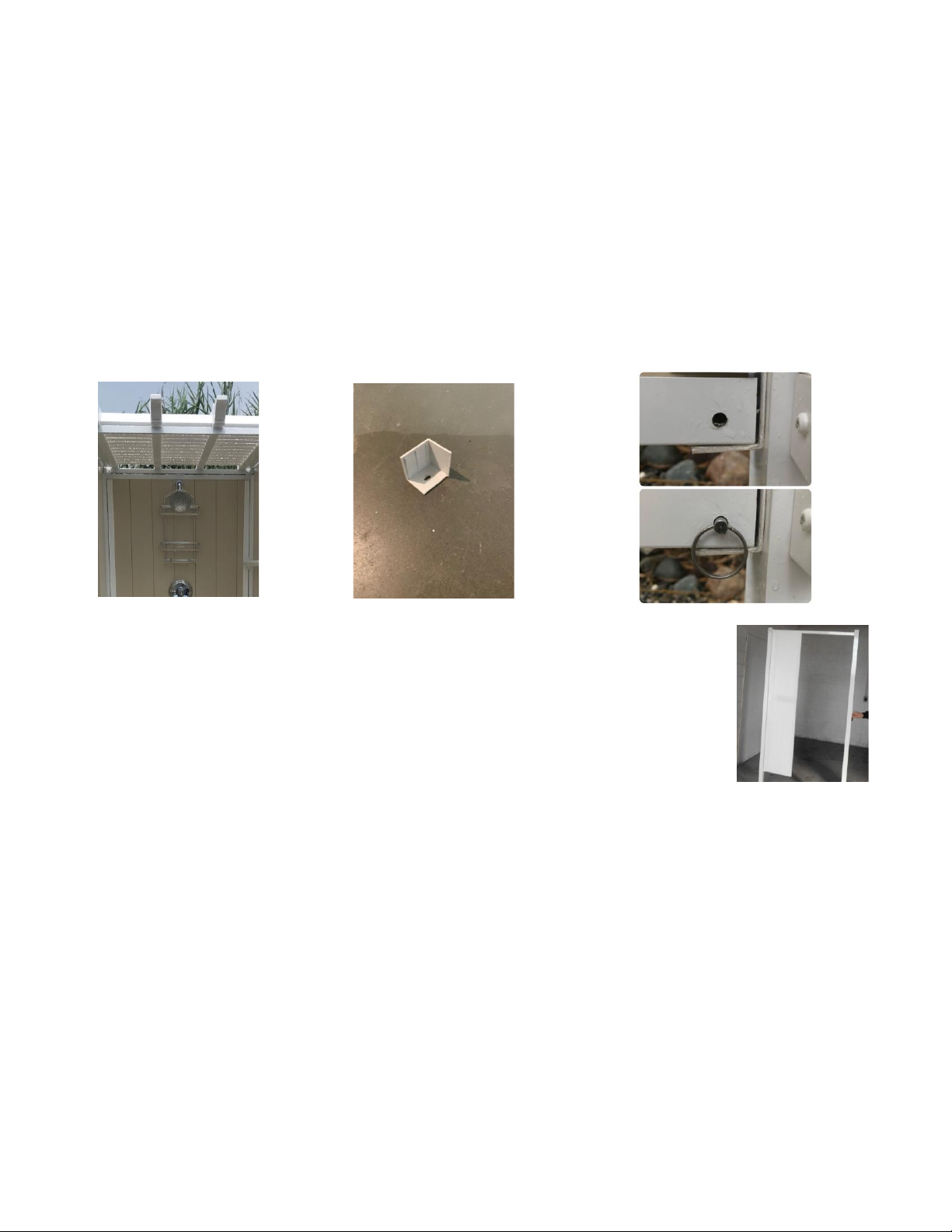
12.) Install the Post Caps: a. Use silicone to secure post cap to the top of each post. Pic 12a
PIC 10a
PIC 10b
PIC 11a
PIC 12a

Caring for your
Vinyl Walls:
•Most dirt can be washed off with a mild soap and water solution.
•Heavier stains can be cleaned with any non-toxic household cleaner.
•On occasion, you may want to spray your SerenityEnclosures with a garden hose. This will
remove grass clippings, dirt and fertilizer chemicals and keep it looking as new as possible.
•To remove minor stains, use a non-abrasive liquid cleaner. For removal of major stains, try
one of the following cleaning agents: *Simple Green, Mr. Clean Magic Eraser, Mineral Spirits,
Trichloroethylene, *CLR (Calcium, Lime and Rust Cleaner) or vinegar.
Decking:
With very little effort, you can keep your decking clean.
•Wash using a soft cloth or ordinary soft bristle brush.
•General cleaning can be done using soap and water.
•When dealing with persistent stains do not use an abrasive cloth, pad or cleaner that could
scratch the vinyl surface. We recommend using foam cleaning pads such as Mr. Clean®
Magic Eraser® or Scotch-Brite™ Easy Eraser. (Excessive rubbing pressure may remove the
glossy shine from the vinyl product.)
•Do not use cleaners containing aggressive organic solvents because they could affect the
surface appearance of the vinyl. Examples of such cleaners are: straight chlorine bleach,
liquid grease remover, strong soaps and detergents containing organic solvents, nail polish
remover and furniture polish/cleaners.
•Power washing is an acceptable method for cleaning our decking product.
•(Pressure washer should be set to manufacturer’s recommended setting for
vinyl to avoid damage.)
•It is recommended to test any cleaning product in an inconspicuous area before
applying on the full vinyl surface
•For difficult to remove dirt and stains you may use the following cleaners: Fantastik®,
Lysol®, Windex® or a mixture of water and vinegar.
Note: Some spray-on bug spray and sunscreen products may cause discoloration of the vinyl
product surface. It is recommended to apply these products away from your Serenity Enclosure.
Do not use any harsh cleaning products on aluminum components. You do not want to remove the
powder coating.

NDH Manufacturing, LLC. warrants to the purchaser of its Aluminum/Outdoor Shower enclosure product that it is free of defects in workmanship and
materials and in the course of normal and proper use, it’s Shower Aluminum/Vinyl parts will not crack, peel, blister, flake, nor be subject to abnormal
weathering per AAMA 2604 Specifications and as per ASTM F964 Specifications.
This warranty covers:
•Any defect in materials and workmanship.
This warranty will be effective:
•For the lifetime of the original owner of real estate upon which the material is installed. Name and address will be kept on file with your dealer or NDHM.
This warranty applies to:
•The purchasing owner. Proof of Purchase must be provided. This is a Limited Lifetime Warranty.
•The Limited Lifetime Warranty applies only to living entities, Non-living entities shall include but not be limited to governments, municipalities, corporations,
commercial operations, and condominiums.
Limitations and conditions not covered:
•The door hardware is covered for one (1) year from time of purchase.
•Damage caused by sandblasting or weather conditions similar to that of sandblasting.
•Damage caused by faulty installation, or from improper application. (NDHM provides an installation manual to follow for specific instructions).
•Damage attributed to fire, violent storms, earthquakes or other Acts of God, accidents, vandalism, or other casualties, impact of objects or exposures to
atmospheric pollutants or conditions other than natural weather processes.
•Damage or discoloration due to misuse, abuse, abrasion and improper storage or to alteration of the material, paints, chemicals or other substances not
recommended for the Shower Enclosure.
•Any materials not supplied by NDHM, LLC. Cost of installation or removal, freight and similar costs.
•Any incidental or consequential damages.
Other Considerations:
•The manufacturer of this material does not recommend or approve this material for all possible end use application. This warranty gives you specific legal
rights, and you may also have other rights that vary from state to state.
Warranty Claim Process:
•Contact the dealer or distributor that sold or installed the Outdoor Shower or write to: NDHM, LLC. 1316 E. Bay Avenue Manahawkin, NJ 08050. You can
email NDHM at sales@serenityenclosures.com within 30 days of discovering the claimed defect.
•If the Outdoor Shower Enclosure components are found to be defective and covered by this warranty, NDHM, LLC will provide replacement of the defective
shower products.
•THIS WARRANTY DOES NOT COVER THE SHOWER VALVE TRIM SET.
•Labor is warranted for one year.
THE WARRANTY STATEMENT CONTAINED IN THIS LIMITED WARRANTY SET FORTH THE ONLY EXPRESS WARRANTIES EXTENDED BY NDHM, LLC FOR ITS
ALUMINUM/VINYL OUTDOOR SHOWER PRODUCTS AND THE PROVISIONS OF THIS WARANTY SHALL CONSTITUTE THE ENTIRE LIABILITY OF NDHM, LLC AND
THE PROPERTY OWNER’S EXCLUSIVE REMEDY FOR BREACH OF WARRANTY. NO OTHER WARRANTY, WRITTEN, MADE BY NDHM, LLC. OR ANY AGENT
THEREOF, WHICH IS NOT CONTAINED OR AUTHORIZED HEREIN, WILL BE RECOGNIZED BY NDHM, LLC.
………………………………………………………………………………………………………………………………………………………………………………………………………
REGISTRATION CARD: Fill out and mail within 30 days of receiving to register your product.
To: NDH Manufacturing, LLC. 1316 E. Bay Ave. Manahawkin, NJ 08050 or email sales@serenityenclosures.com
Warranty Registration & Validation
Name: ___________________________________ Retailer: _________________________________________________
Address: _________________________________ City: ________________________ State: _______________________
City: _____________________________________ Installer Name: ____________________________________________
State: __________________ Zip: ______________ City: ________________________ State: _______________________
Phone: ( ) _____________________________ Installation Date: __________________________________________
Email: __________________________________________
This manual suits for next models
9
Table of contents
Popular Shower Cabin manuals by other brands

Artweger
Artweger TwistLine 5TR0 Series Assembly instructions

ERLIT
ERLIT Elegance ER 5508TP Installation and operation instruction

Aurlane
Aurlane ECLIPSE ROUND CAB129 manual

Schulte
Schulte Garant D80310 manual

ERLIT
ERLIT Elegance ER 05509 Installation and operation instruction

Kohler Mira
Kohler Mira Indigo E44W01-GA Fitting instructions


