Serigstad FLEXIFEED User manual

INSTRUCTION MANUAL
08.07.2019
Automate heavy and time consuming work!
FLEXIFEED
Etbl. 1864

CONTENTS
INTRODUCTION
DECLARATION OF CONFORMITY
SAFETY
INSTALLATION
CONNECTING
CUSTOMIZATION
USE
MAINTENANCE
TROBLESHOOTING
SPARE PARTS
OPTIONAL EQUIPMENT
RECYCLING
CONTACT
3
4
5 - 11
12
13 - 15
17 - 19
21 - 22
23 - 25
26
27 - 34
35 - 38
39
40
A great deal of the heavy silage
handling is taken away due to
Serigstad feed solutions.

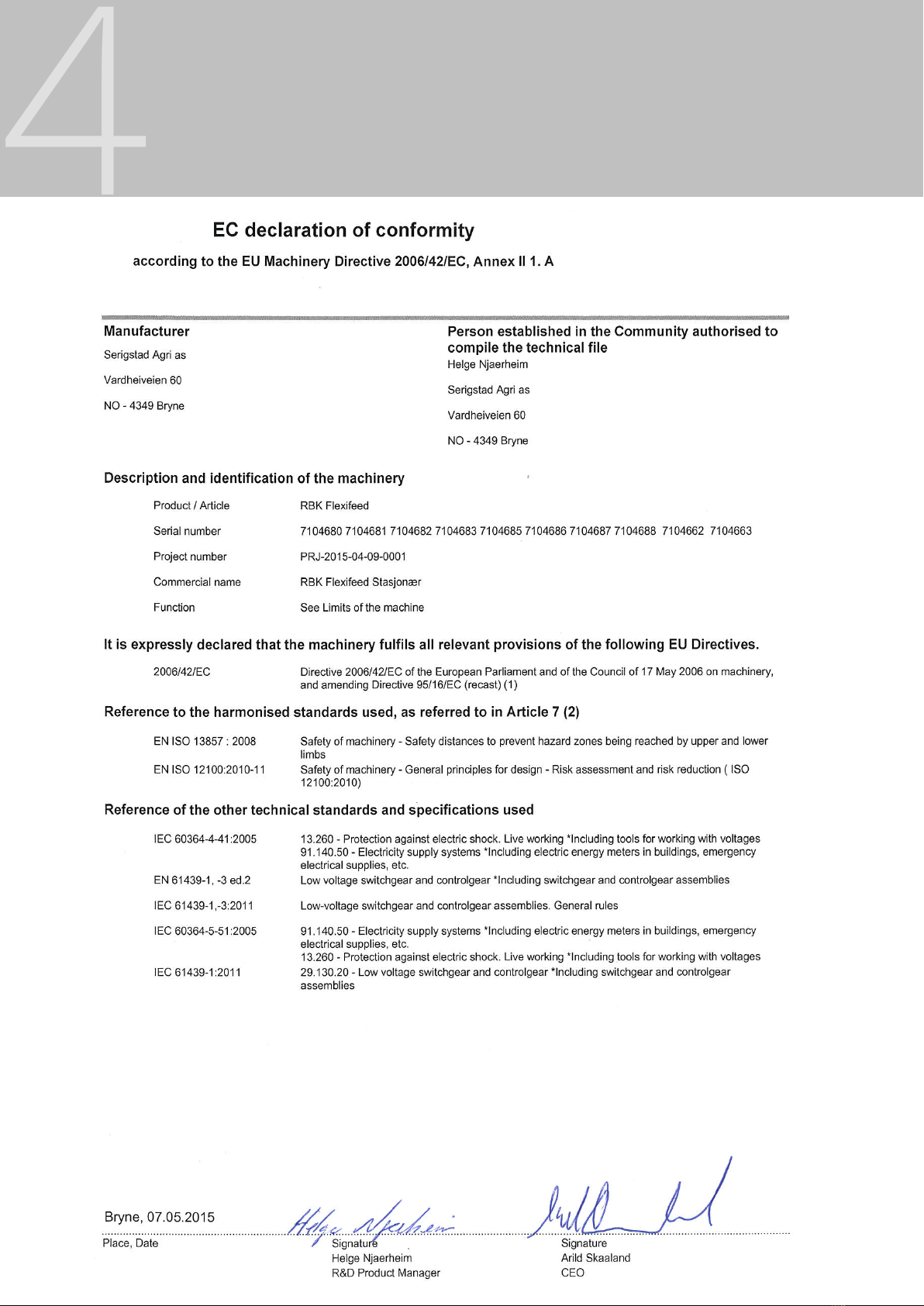
We appreciate the trust shown to our company purchasing Serigstad
FlexiFeed. The product is tested and built on a highly reliable and known
technology. The product fulll strict safety and quality requirements.
On delivery our distributor will give you information about control,
maintenance and adjustments on the machine. The brief introduction
is not a compensation for the more detailed and necessary information
given in this instruction manual.
This instruction manual includes detailed safety instructions, use and
maintenance guidance, knowledge of functions and use of FlexiFeed.
Dear customer!
INTRODUCTION
The system has one year warranty against fabrications- and material
defects. Serigstad Agri reserve the right to change the design without
obligation for previously delivered products.
We hope the product meets your expectations and needs!
Best regards
Helge Njærheim
Research & Development Manager
Serigstad Agri
4
DECLARATION OF CONFORMITY
SAFETY INSTRUCTIONS
DANGER
WARNING
WARNING!
ALWAYS CHECK MACHINE BEFORE USE TO ENSURE PROPER AND SAFE
OPERATION.
COVERS AND PROTECTIVE MEASURES MUST ALWAYS BE CLOSED DURING
OPERATION.
KEEP VISUAL SUPERVISION OF MACHINE DURING STARTUP AND OPERATION.
MACHINES PLACED ON STANDS, PLATFORMS OR IN RAILS MUST BE
SECURED WITH OBSTRUCTIONS OR SAFE ZONE TO PREVENT ACCESS TO
HAZARD AREAS.
Indicates an imminent dangerous situation which, if not avoided, may
result in serious injury or death.
Indicates a potential dangerous situation which, if not avoided, may
result in serious injury.
The label shows exposed danger areas when he covers are opened or
removed.

SAFETY
6
Read instruction
manual before use.
Keep distance to run-
ning equipment.
Do not stand in danger
zone during startup or
operation!
Serial number plate
Lifting: See dened lifting points labeled on
machine.
Use labeled points when lifting the machine.
Use labeled points for lifting the machine with forklift.
Keep clear to hanging load!
SAFETY FIRST!
Crushing hazard, op-
erating machine can
cause serious injury
or death.
Transport
Covers must be closed
during operation.
Figure 1 FlexiFeed with machine labels
DANGER ZONE
Tighten conveyor belt after
use of new machine.
(Paint is worn o).
Check frequently!

SAFETY
Danger sign 996745 - red zone
WARNING! Disconnect power supply before entering
high risk area for maintenance or adjustments.
Standing in danger zone during operation may cause
serious injury or death.
Warning sign 996746 - red and yellow zone
Be careful! High voltage. Disconnect power supply
before opening control cabinet.
Warning sign 996763 - red zone
Be careful! Crushing hazard that may cause serious
injury or death! Keep distance when machine is
running.
Warning sign 996766 - red zone
Be careful! All covers must be closed when machine
is running. Fingers and limbs can be damaged if they
are in contact with rotating parts.
Warning sign 7996765 - red and yellow zone
Be careful! Keep distance to running equipment. Do
not stand in hazard area during startup or operation.
Objects may be thrown out of machine during
operation.
Warning sign 996760 - red and yellow zone
Be careful! Make sure you read and understand the
instruction manual before startup, maintenance and
adjustments are made.
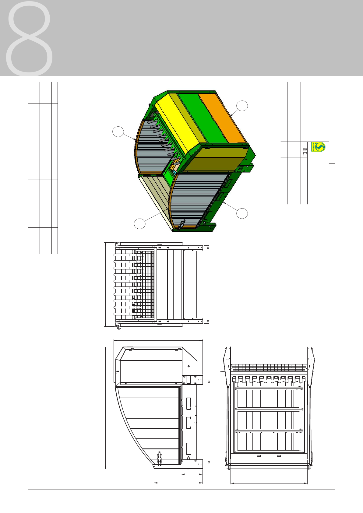
DIMENSIONS
8
Figur 2 Dimensional sketch of FlexiFeed
2 1
4
3
1386,0
1649
1529,0
T1
16.10.2012
RBK Flexifeed
Weight
Material: Thickness: Surface treatment:
Sheet scale: Drawing number. Revisjon:
Serigstad Agri AS
Helge
Projection:
Content in: Replaced by:
A3
Designed by:
Project:
RBK Flexifeed
1:1
Helge
7104682
NS-1430:
Tolerance not specified according to:
390
1606
881
2392
1652
ITEM NO. PART NUMBER DESCRIPTION QTY.
1 17036 Montert frontseksjon 1
2 17035 Bunnramme 1
3 17058 Høyre sidedør 1
4 17059 Venstre sidedør 1
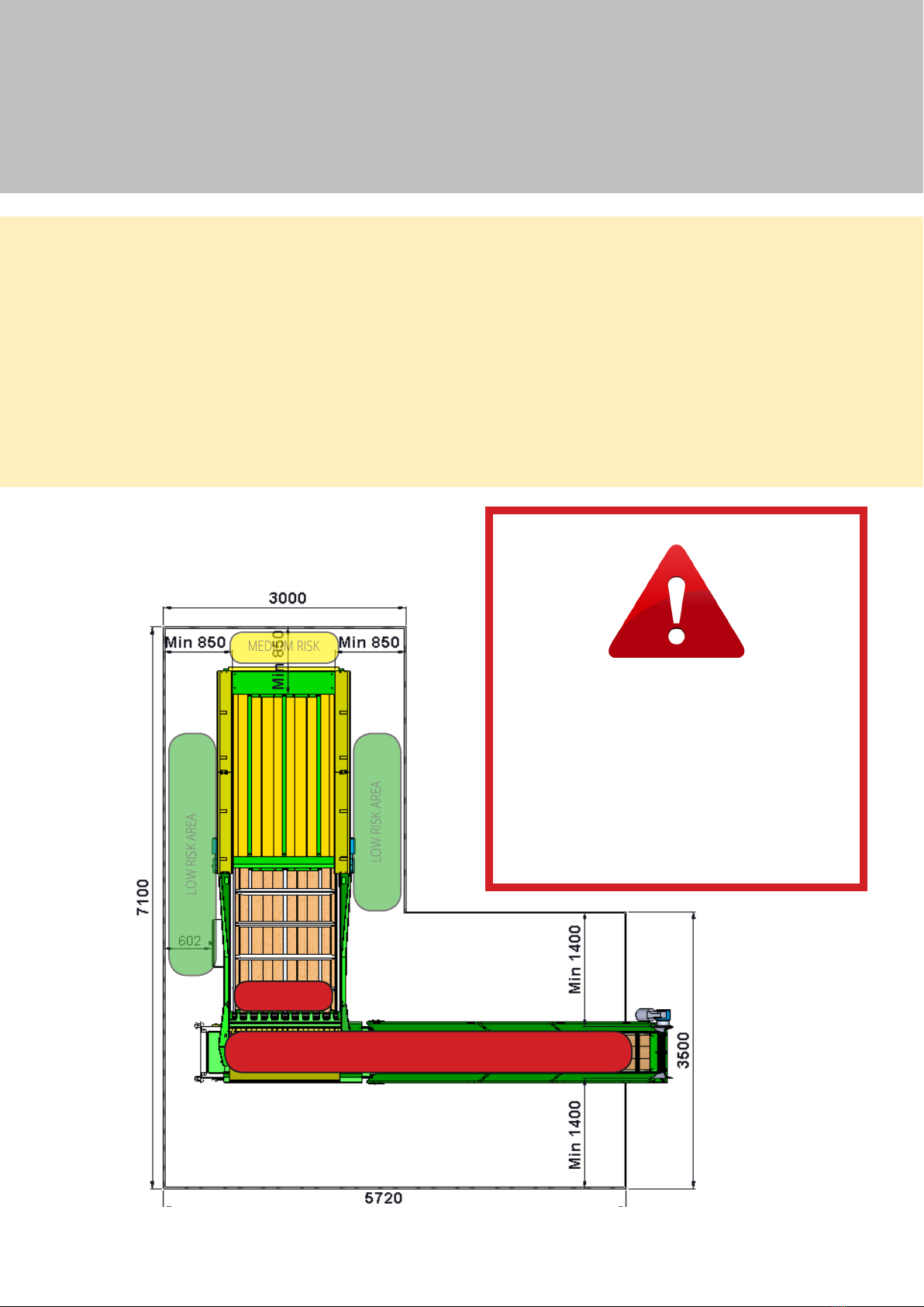
HAZARD AREAS
HIGH RISK AREA
LOW RISK AREA
MEDIUM RISK
LOW RISK AREA
HIGH RISK AREA
Outside safety barrier = low risk zone
Inside safety barrier = high risk zone
Safety zones around the equipment with
minimum distances must be followed to
prevent damage to humans and animals.
Before entering high risk areas for
maintenance, adjustments or repairs,
always turn o and lock the main power
switch.
Represents hazard area which may cause serious injury during operation
Represents potential hazard area which may cause accidents and injuries
during operation.
Represents low risk of accidents and injuries during operation
Red area
Yellow area
Green area
Figure 3 Hazard areas around FlexiFeed
10
HAZARD AREAS
SAFETY FUNCTIONS
• Emergency stop button is placed on front of control cabinet.
• Lockable main power switch is placed on left side of control cabinet.
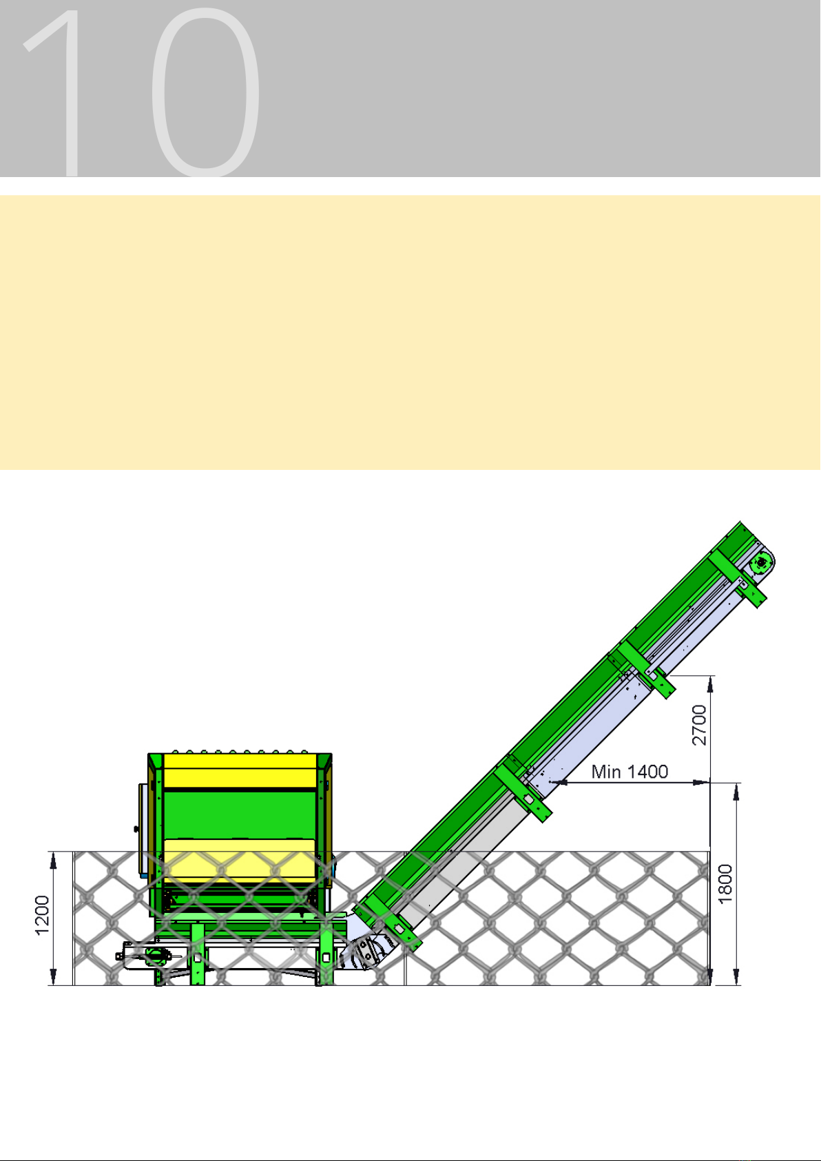
Figure 4 FlexiFeed with chained conveyor and safety fence.
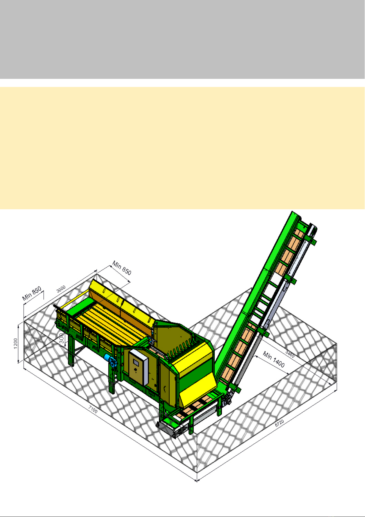
HAZARD AREAS
Height of safety fence (according to standard: EN ISO 13857:2008):
• If FlexiFeed is raised with extended leg set, the height of the safety fence must be at least
300 mm higher than the lower frame on the feed table. See gure 4 and 5.
• As an alternative to higher safety fences all distances of at least 850 mm can be raised to a
minimum of 1400 mm.
• Minimum recommended distance from safety fence to conveyor is 600 mm, safety fence
towards the conveyor is always to be a minimum of 2000 mm high.
Conveyor
Figure 5 FlexiFeed with feed table,
chained conveyor and safety fence.
INSTALLATION
12
INSTALLATION OF EXTENSION LEGS AND SUPPORT RODS
When extended leg sets are used for FlexiFeed, and optionally free standing or integrated feed
table, it is important to assemble the support rods correctly. The legs on the FlexiFeed as well as
the feed table are mounted to the oor, taking the oor material and quality into account. The
support rods are then mounted on the legs.
Figure 6 FlexiFeed with integrated feed
table. If the feed table consists of multiple
sections, the support rods are placed in the
top position.
On the machine itself the legs are mounted in the
lowest position, due to the design of the machine.
On the feed table the support rods are assembled
on the highest position. This takes care of the
loads and stress on the feed table during loading
of bales. Mounting the support rods in the top
position makes it easy to access the underside of
the machine for cleaning and maintenance.
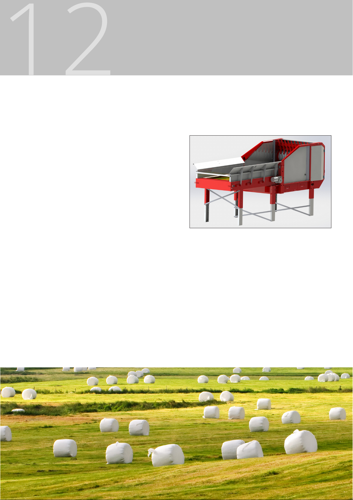
FLEXIFEED VERSIONS
FlexiFeed can be delivered in a range of dierent
versions to suit your installation. It is possible to
have xed sides, or one or two side doors for
loading from the side. The standard length is
240 cm long. A 280 cm version with xed sides is
available.
A version with integrated feed table is also available (shown in gure 6).

CONNECTING
CONTROL CABINET
The control cabinet is factory-tted and assembled in front or on either side of the machine,
according to the order.
Always keep the machine under observation during operation to avoid damage to people or
animals.
All connections must be performed by authorized personnel.
VOLTAGE
FlexiFeed is available in 230V and 400V versions.
Motor eect 230 V 400 V
Cutter 7,50 kW 25,35 A 14,64 A
Conveyor belt 0,75 kW 3,34 A 1,93 A
CrossFeeder 0,75 kW 3,34 A 1,93 A
Conveyor (external) 2 x 2,20 kW 8,34 A 4,34 A
Feed table 2 x 0,55 kW 2,85 A 1,65 A
Recommended fuse size
3 phase + ground for 230 V
3 phase + neutral + ground
for 400 V
Min. 35 A Min. 25 A

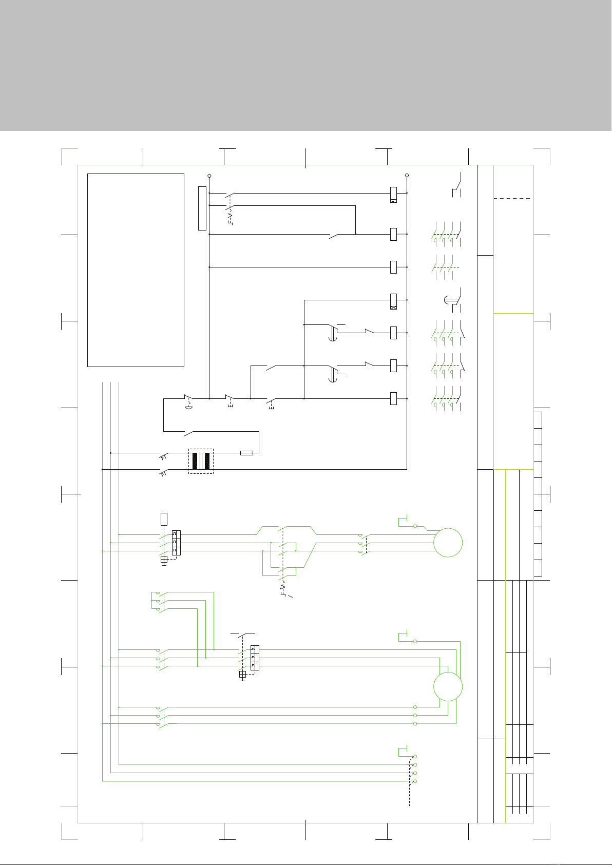
CONNECTION 230V
14
-S3
-X1-X1
FLEXIFEED FFS-7,5kW 230VAC (7466827)
(+ STEPP/CYKL)
STYRESKAP
FLEXIFEED FFS-11kW 230VAC (74668**)
-X1
-K2
-K1
-K3
3E-06/916
-F2
-K1T
-K3
-K2
-K4T
-K4
-Q1
-K4
-K1T
-S2
-K1
-S1
-K1
-K2
-K3
-Q2
-FA1
-F2
-Q1
-S0
-K1T
-K4T
-S4
-X2 -X2
10 9
2 1
4 3
6 5
8 7
REVERS-0-START
v
3x230 V AC / max. 40 A
STROMTILFORSEL
Revision
Revision
1
F
PG29, 2xPG16
E
PG29, PG21
L3
L1
L2
[11 kW]
(add)
L1
L2
L3
STYRESTROM 230V AC
Circuit diagram
0,75 kW7,5 kW [11kW]
KABEL F.TRANSPORTBELTE 230VAC
Nákladní 1032, 415 01 TEPLICE, CZ
EMCOS
s.r.o.
KABEL HOVEDMOTOR 230VAC-7,5kW; [230VAC-11kW]
04.12.2003
Date
Assembly place
2
Prepared by
Agreed by
Molnár
Molnár
SERIGSTAD AS, Norway
3
FLEXI4S.dwg
Order No.
Ident.
Title
6
PE
RUNDBALLEKUTTER
W1
U1
V1
PE
W2
3~ U2
V2
M
3
2
1
PE
PE
TRANSPORTBELTE
PG13,5
V1
U1
PE
W1
3~
M
14
22
13
/.6.C /.6.D
21
/.2.B /.3.B
PE
A2 A1
A2 A1
/.6.E
22 21
7
Drawing No.
8
Index
F
13
22
16
18 15
21
/.6.D /.6.D
/.3.B /.4.B
14
16
18 15
STEPP/CYKL 230V AC
/.7.D
/.4.D
E
D2 D1
A2 A1
A2 A1
U<
/.6.E
22 21
A2 A1
A2 A1
D
C
B
A
1
Q1/7,5kW
Q1/11kW
4
2
[23A]
16,3A
I> I>
14 13
6
I>
/.5.B
16
/.7.E
18 15
4
6
2
/.8.E
3
5
1
START
13 14
4 3
/.6.E
STOPP
2 1
/.6.E /.6.E /.6.E
U<
I>I> I>
/.7.E
4 3
2 1
v
v
B6A
14 13
/.3.C
1 2
NODSTOPP K1T
FA1
K3
Q2
F2
L3
3PE AC 50Hz 230V
K2
K1
L1
L2
16
/.7.E
18 15
/.8.E
15 18
D
C
14 13
GV-AU225 (220-240VAC)
RE11 RA MU (10s, 24-230VAC)
C60H-B6A, 2P
B
S4
S3
S2
S1
S0
LC1-D12 P7(M7)
GV2-ME20, GV-AE1
GV2-ME21, GV-AE1
GV2-ME08
LC1-D25 P7(M7)
LC1-D25 P7(M7)
ZB5-AA3, ZBE-101 (NO)
A
K1SE 54602Z
ZB5-AD3, 2x ZBE-101 (NO)
ZB5-AA4, ZBE-102 (NC)
ZB5-AS844, ZBE-102 (NC)
2345678
21
2AC 50Hz 230V
PG16
K4T RE11 RL MU (24-230VAC)
LC1-D09 P7(M7)K4
PG13,5
a) 21.06.04
d
b) 25.01.05
24 23
NORMAL-0-STEPP
c) 09.05.06
d) 21.09.06
AD VB8/4
2xAD VB8/4
-CYA6/4
1xWK4SL/U
-CYA0,75
-CYA2,5 -CYA2,5 -CYA2,5 -CYA1,5
3xWK4/U 1xWK4SL/U
2xWK2,5/U, 1xWK4SL/U
6xWK6/U, 1xW6SL/U,
3xWK6/U, 1xW6SL/U,
CONNECTION 400V
FLEXIFEED FFS-7,5kW 400VAC (7466828)
FLEXIFEED FFS-11kW 400VAC (74668**)
(+ STEPP/CYKL)
STYRESKAP
-X1
-X1
-K1
3E-06/917
-K3
-K1T
-K2
-K3
-K2
-K4T
-K4
-F2
-Q1
-S2
-S1
-FU1
-K1
-K2
-K3
-FA1
-Q2
-F2
-Q1
-S0
-T1
-K1T
-K1T
-K4T
-K1
-K4
-X2
-X2
-S3
-S4
STROMTILFORSEL
3x400 V AC / max. 25 A
Revision
F
E
/.6.C
/.2.B
0,75 kW7,5 kW [11kW]
FLEXI4S.dwg
SERIGSTAD AS, Norway
KABEL HOVEDMOTOR 400VAC-7,5kW; [400VAC-11kW]
Agreed by
Assembly place
Prepared by
Revision
Date
12
04.12.2003
3
Molnár
Molnár
Ident.
Order No.
EMCOS
s.r.o.
Nákladní 1032, 415 01 TEPLICE, CZ
KABEL F.TRANSPORTBELTE 400VAC Title
W1
V1
PG29, PG21
PE
RUNDBALLEKUTTER
W2
U1 3~ U2
V2
M
1
PEN
2
3
PE
TRANSPORTBELTE
13
Drawing No.
Circuit diagram
678
Index
F
18 15
16
STEPP/CYKL 230V AC
18 15
22
16
22
14
STYRESTROM 230V AC
21
/.6.D /.6.D
21
/.6.D
/.3.B /.3.B
13
14
/.4.B /.4.C
A2 A1
A2 A1
A2 A1
A2 A1
/.6.E
22 21
/.6.E
22 21
A2 A1
D2 D1
U<
/.7.D
E
A2 A1
D
C
B
A
3PEN AC 50Hz 400V
0 0
230 400
14 13
4
I>
9,3A
I>
2
[13,1A]
I>
6
/.5.B
2A
2 1
START
STOPP
/.6.E /.6.E /.6.E
U<
I>I> I>
/.7.E
14 13
400/230V
100VA
/.3.C
4 3
2 1
v
v
B6A
NODSTOPP
16
/.7.E
18 15
/.7.E
16
18 15
/.8.E
15 18
4 3
13 14
/.6.E
2 1
D
C
14 13
1 2
L3
L1
L2
B
A
12345678
3
5
3~
M
V1
U1
2
PG13,5
PE
W1
PE
4
6
/.8.E
1
PG13,5
1
2
LC1-D09 P7(M7)
LC1-D18 P7(M7)
LC1-D18 P7(M7)
LC1-D09 P7(M7)
C60H-B6A, 2P
GV2-ME07
GV-AU225 (220-240VAC)
RE11 RA MU (10s, 24-230VAC)
GV2-ME14, GV-AE1
GV2-ME16, GV-AE1
RE11 RL MU (24-230VAC)
K1T
FA1
Q2
F2
K4T
K3
K2
K1
K4
Q1/7,5kW
Q1/11kW
CSTN100, 100VA
400/230VAC
ASK1, SF-2A/250VFU1
T1
6 5
v
2 1
4 3
10 9
8 7
L3
L1
L2
(add)
PG16
ZB5-AA3, ZBE-101 (NO)
ZB5-AA4, ZBE-102 (NC)
ZB5-AS844, ZBE-102 (NC)
K1SE 54602Z
ZB5-AD3, 2x ZBE-101 (NO)S4
S3
S2
S1
S0
NORMAL-0-STEPP
24 23
c
a) 25.01.05
b) 09.05.06
c) 21.09.06
REVERS-0-START
AD VB8/4
3xWK4/U
-CYA2,5
-CYA0,75
-CYA2,5 -CYA2,5 -CYA2,5 -CYA1,5
1xWK4SL/U
2xWK2,5/U, 1xWK4SL/U
3xWK6/U, 1xW6SL/U, 1xWK4SL/U
16
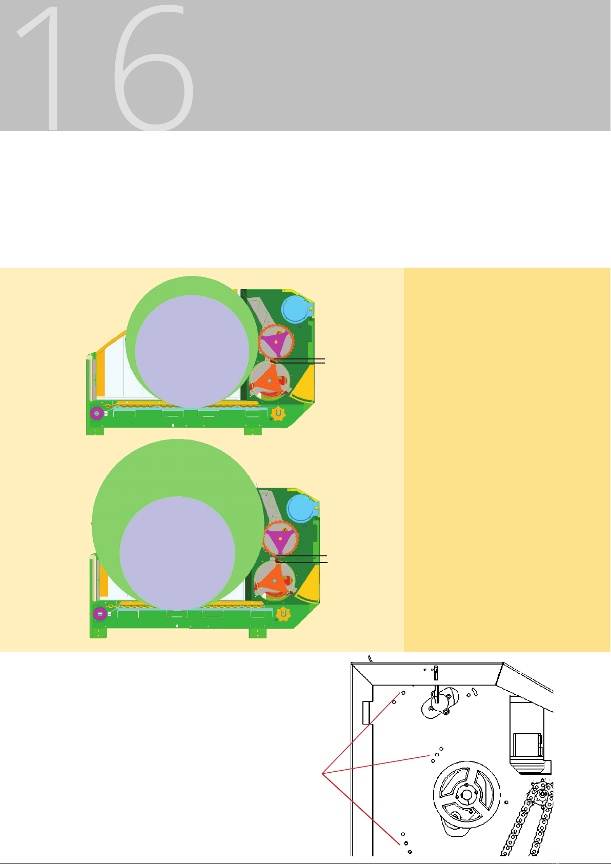
CUSTOMIZATION
Figure 7 The smallest
opening between knife drum
and spiked reel. Maximum
recommended bale size is
1,4 m diameter.
1,4 m
Figure 8 The largest
opening between knife
drum and spiked reel.
To adjust drum opening, remove
these three bolts on each side.
Place gate in desired position and
fasten bolts
Figure 9 Holes for adjusting the drum opening
DRUM OPENING AND BALE SIZE
There are three selectable drum openings to choose from.
- Minimal drum opening processes the grass more and prolongs operating time.
- The centre drum opening is the factory setting, and is used in most cases.
- Large drum opening for bales with diameter 1,8 m and high capacity.
1,8 m
1,4 m

TILPASNING AV MASKIN

18
KNIFE SETUP
TYPES AND PLACEMENT OF KNIVES
FlexiFeed is delivered with a knife drum capable of holding up to 60 knives as standard.
Correct type and placement of knives is important to ensure optimal feeding as well as reliable
operation. The choice is governed by several factors including dry matter content, reliability and
cutting rate.
As a starting point a standard set of 20 standard knives, placed in the pattern as shown on next
page, is recommended for FlexiFeed.
The number of knives can be increased with the intention of increasing
the rotation of the bale and thereby increase the capacity. Increased
number of knives will not necessarily provide better cutting, as the extra
knives will go in the same groove as the knives in the standard setup. If
it is desirable to increase the number of knives, the rear row on every
segment may be lled, for a total of 40 knives, or ll all holes with 60
knives for reduced feeding. This is only examples on possible solutions.
To nd out which setup works best for your conditions, use the standard
setup as a starting point and then adapt the setup to the actual
conditions until desired cutting length is achieved.
Figure 10 Knife for
reduced feeding.
Figure 11
Standard knife
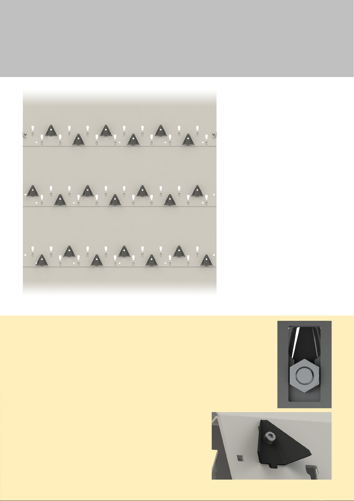
KNIFE SETUP
Flattened view of knife drum with
standard setup with 20 knives.
This setup gives a balanced
rotation of the knife drum. The
scrapers are placed on both
sides of the segment with fewer
knives, as shown on the rst row
on gure 12.
REPLACING KNIVES
The knives are secured with a bolt and a nut that
goes into a keyhole slot in the drum. To replace the
knife, loosen the bolt a little bit, the knife is then
loose and can be pushed up and taken out the wide
part of the keyhole. The nut is held by the geometric
design of the keyhole. Make sure not to loosen too
much, the nut will then fall o and into the drum.
New knives are assembled by placing bolt and nut in
the wide end of the keyhole, push down and secure
the knife by tightening the bolt. Make sure the pin
on the back of the knife is placed in the slot on the
drum.
Figure 12 Flattened knife drum with standard knife setup.
Figure 13 Inside of
the drum, with nut
in the keyhole slot
which is used for
fastening the knife.
Figure 14 Knife assembled to the drum.
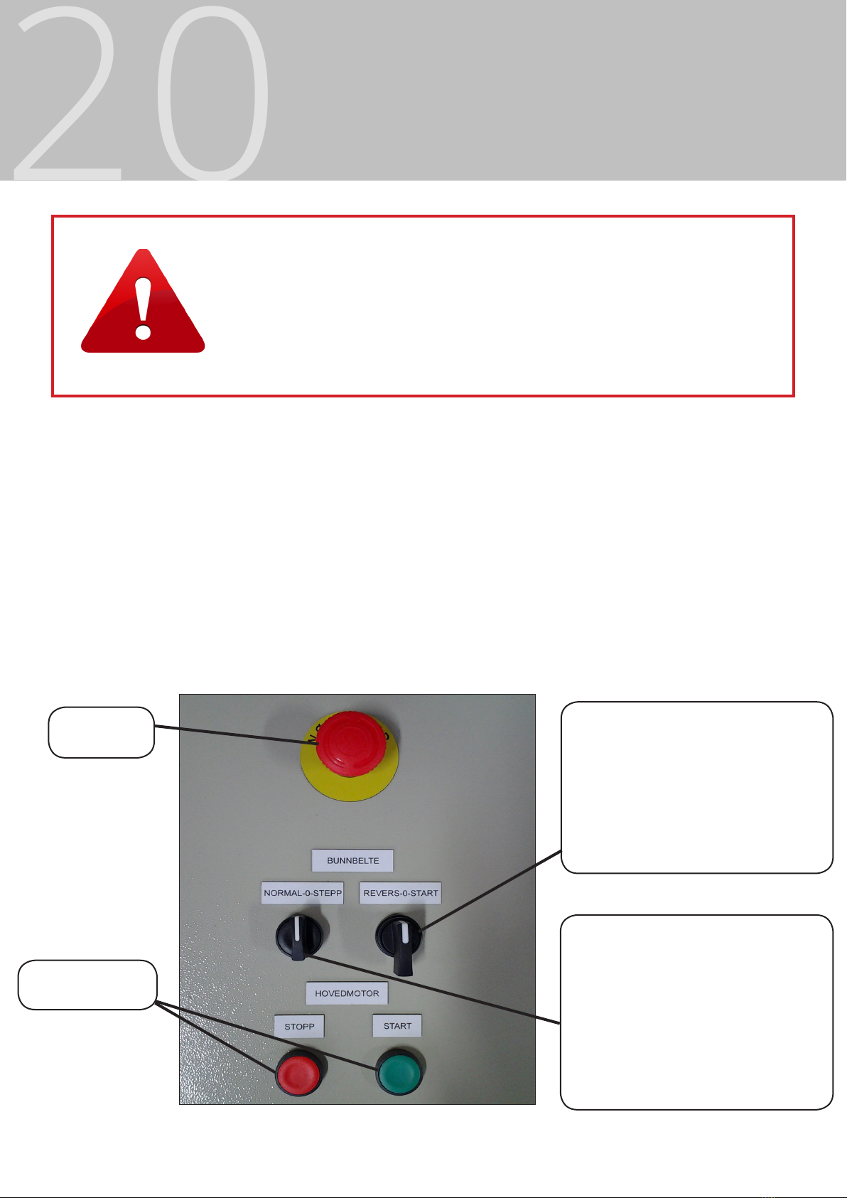
USE
STARTUP PROCEDURE
1 Reverse the conveyor belt for a maximum
of 3 seconds
2 Start the main motor
3 Select operating mode (normal or step)
4 Start conveyor belt and feeding starts
20
NB! Unplug power before performing service or maintenance!
Make sure no animals or people are located in hazard areas before
startup.
Due to the aforementioned reasons, it is not allowed to extend the cables
for the control cabinet to control the machine from a dierent room.
Emergency
stop
OPERATING MODE
Normal Continuous feeding.
Stepp Reduced feeding. Is used
to easy startup and feeding with
silo, soft or new bales.
CONVEYOR BELT
Revers Benyttes først dersom
det ligger fôr inntil kuttetrommel
før oppstart av hovedmotor.
Start Kjøring av bunnbelte.
Main motor stop
and start button
Figure 15 Operating the control cabinet
STOP PROCEDURE
1 Stop conveyor belt
2 Press stop button
3 The machine stops
Note!
It is very uncommon that the motor protection for the conveyr belt is activates. In these rare
cases, a voltage loss over 20% has been present. Contact electrician for power upgrade.
Table of contents
Other Serigstad Farm Equipment manuals

Popular Farm Equipment manuals by other brands


Valtra
Valtra BP603 Workshop service manual

Workzone
Workzone AET14 user manual

Amazone
Amazone Precea 3000 Original operating manual

Landoll
Landoll Tilloll 877 Operator's manual

Concept Perugini
Concept Perugini PTR Series Instruction book

Pottinger Landsberg
Pottinger Landsberg EUROCAT 311 ALPHAMOTION MASTER Operator's manual


