Concept Perugini PTR Series User manual

INSTRUCTION BOOK
Manufactured by
CONCEPT PERUGINI S.R.L.
Via Dell’Artigianato, 11-15
47014 Meldola (FC)
Italia
TEL.: +39 0543494602
FAX: +39 0543 494727
www.conceptagri.com
CONCEPT PERUGINI S.R.L. RESERVES THE RIGHT TO MODIFY THEIR
PRODUCTS WITHOUT PRIOR NOTICE AND THE COMMITMENT TO UPDATE
THIS MANUAL
FLAIL MOWERS
CONCEPT PERUGINI S.R.L. RESERVES THE RIGHT TO MODIFY THEIR
PRODUCTS WITHOUT PRIOR NOTICE AND THE COMMITMENT TO UPDATE
THIS MANUAL
CONCEPT PERUGINI S.R.L. RESERVES THE RIGHT TO MODIFY THEIR
PRODUCTS WITHOUT PRIOR NOTICE AND THE COMMITMENT TO UPDATE
CONCEPT PERUGINI

INDEX
Introduction . . . . . . . . . . . . . . . . . . . . . . . . . . . . . . . . . . . . . . . . . 3
Instruction Manual. . . . . . . . . . . . . . . . . . . . . . . . . . . . . . . . . . . . 4
Identifi cation . . . . . . . . . . . . . . . . . . . . . . . . . . . . . . . . . . . . . . . . 5
Before operation . . . . . . . . . . . . . . . . . . . . . . . . . . . . . . . . . . . . . 5
Safety . . . . . . . . . . . . . . . . . . . . . . . . . . . . . . . . . . . . . . . . . . . . . . 5
Symbols . . . . . . . . . . . . . . . . . . . . . . . . . . . . . . . . . . . . . . . . . . . . 5
General Safety Instruction . . . . . . . . . . . . . . . . . . . . . . . . . . . . . 7
Operator’s Prerequisites. . . . . . . . . . . . . . . . . . . . . . . . . . . . . . . 7
Work Clothing . . . . . . . . . . . . . . . . . . . . . . . . . . . . . . . . . . . . . . . 7
Attaching the machine to the Tractor . . . . . . . . . . . . . . . . . . . . 8
ET Headstock. . . . . . . . . . . . . . . . . . . . . . . . . . . . . . . . . . . . . . . . 8
HT Front or Rear . . . . . . . . . . . . . . . . . . . . . . . . . . . . . . . . . . . . . 9
PTO Shaft . . . . . . . . . . . . . . . . . . . . . . . . . . . . . . . . . . . . . . . . . . 10
Working Depth. . . . . . . . . . . . . . . . . . . . . . . . . . . . . . . . . . . . . . 10
Side Shift . . . . . . . . . . . . . . . . . . . . . . . . . . . . . . . . . . . . . . . . . . 11
In the Field . . . . . . . . . . . . . . . . . . . . . . . . . . . . . . . . . . . . . . . . . 11
Road Transport . . . . . . . . . . . . . . . . . . . . . . . . . . . . . . . . . . . . . 11
Maintenance. . . . . . . . . . . . . . . . . . . . . . . . . . . . . . . . . . . . . . . . 12
Storage . . . . . . . . . . . . . . . . . . . . . . . . . . . . . . . . . . . . . . . . . . . . 15
Spare Parts. . . . . . . . . . . . . . . . . . . . . . . . . . . . . . . . . . . . . . . . . 15
Warranty . . . . . . . . . . . . . . . . . . . . . . . . . . . . . . . . . . . . . . . . . . . 16

3
Introduction
Concept Perugini S.R.L would like to thank you for purchasing this Flail mower
and off er their support and assistance throughout its productive life.
We strongly recommend that this booklet is read and understood before using
your new machine, and that regular maintenance is carried out as described
further in the booklet. If any doubts arise then don’t hesitate to contact your local
dealer or the company via the options provided on the front page or via Facebook
@ Concept Perugini.
We recommend you take a moment to write down the Serial Number, Year of
Manufacture and Model, as this information will facilitate ordering spare parts.
Serial Number:
Year of Manufacture:
Model:
your new machine, and that regular maintenance is carried out as described
further in the booklet. If any doubts arise then don’t hesitate to contact your local
dealer or the company via the options provided on the front page or via Facebook
@ Concept Perugini.
We recommend you take a moment to write down the Serial Number, Year of
Manufacture and Model, as this information will facilitate ordering spare parts.
Serial Number:
Year of Manufacture:

4
Instruction Manual
The aim of this manual is to help you (the user) understand how to use and how
to maintain the machinery. This booklet covers the following models : AT ET JT
HT PT TT
PT PTR
PT PTR
HT
ET
ET
AT
AT
JT
JT
HT
TT
TT

5
Identifi cation
The identifi cation plate, attached to the machine shows the following information:
• Manufacturer’s Name
• CE mark
• Year of production
• Serial number
• Recommended tractor horsepower
• Overall weight
• P.T.O. speed and direction of
rotation
These data are very important in order to check the compatibility between the
machine and the tractor and when ordering spare parts
Before operation
At the factory each machine is carefully inspected to guarantee proper
functioning. In addition, the dealer, before delivering the machine should have
carried out a pre delivery inspection. However as a precaution measure check:
• Oil level in the gearbox
• Grease all those components provided with grease nipples
• Air pressure in the tractor’s tyres, length of lift arms
• Tractor PTO speed to match the machine transmission speed
Safety
Symbols
In this booklet three diff erent symbols are used to highlight danger levels or
important information
DANGER
To draw the operator’s attention to situations which could
endanger his or other people safety.
CAUTION
To draw the operator’s attention to situations which could aff ect
the machine performances but not his or other people safety.
IMPORTANT
To draw the operator’s attention to situations which do not aff ect
the machine performances and his or other people safety.
It is important to comply with the instructions given by the safety stickers, which
must always be on the machine. If new ones are required, contact your dealer.

6
SYMBOL DESCRIPTION
1
Before operation, adjusting
or servicing the machine,
it is important that each
operator carefully reads the
following instructions.
Servicing lubrication etc.
should be carried out with
the engine stopped, the
brakes applied and locked
and the starter key removed.
2
Anybody who is near the
machine when working,
must keep at a safe
distance.
During operation keep away
from rotating parts and PTO
shaft. Do not remove safety
guards whilst the machine
is working or with engine
running.
3
Danger of injury to lower
body parts. Anybody who
is near the machine when
working must keep a safe
distance at all times.
4
Danger of injury to limbs.
Anybody who is near moving
parts must be aware of
where his body is in relation
to the machine and keep
at a safe distance. Do not
remove safety guards.
5
Any servicing should be
carried out with the tractor
off and the correct parking
procedures should be
followed out as advised by
the manufacturer. Should
the machine need to be
raised it should be supported
securely.

7
General Safety Instruction
• During operation keep away from rotating parts and PTO shaft, do not
remove safety guards during operation or with the engine running.
• Servicing should be carried out with the engine stopped, the brakes applied
and locked and the started key removed. Once the machine is raised do not
work underneath unless supported securely.
• When travelling on the public road disconnect the PTO shaft and carefully
follow the traffi c regulations of your country.
• Always lift the machine from the lifting points.
• The operator should be experienced and in good health in order to avoid
injury to his person and others.
• The operator must wear the correct safety garments.
• Do not work when dark unless suitable lighting is available
Operator’s Prerequisites
To avoid danger to himself and others, the operator must be:
• Physically sound
• Mentally sound
• Trained
We advise that the operator read and understand this booklet before using
the machinery. If there are any doubts then contact your dealer or CONCEPT
PERUGINI S.R.L
Work Clothing
The operator must wear the following:
• Working gloves
• Overalls of appropriate size
• Working boots
• Protective glasses
• Protective helmet
When lifting the machine always use the appropriate lifting gear
and always use the lifting points indicated by the yellow and black
stickers as shown in picture.

8
Attaching the machine to the Tractor
Concept Perugini Flail toppers can be linked up to any tractor with a category 1
or 2 three point linkage.
Read the tractor’s instruction manual before attaching attempting to attach the
machine to the tractor.
• Adjust the width of the tractor arms to match the lower brackets on the
machine
• On a fl at surface reverse the tractor up to the machine
• Firstly attach the lower links and do the necessary adjustments to limit
sideways movement
• Lengthen and attach the top link in order to have the machine parallel to the
ground once attached
• Remember to fi t all the locking pins and that the machine is safely secured
to the tractor
NB On the PT the top link bracket is provided with a hole and a slot to attach the
tractor’s top link. It is important that during transport the top link is secured via the
hole and during work the slot is used. Failing to follow these instructions could
result in serious damage to the headstock sliding mechanism and to injury.
ET Headstock
The ET comes with a fi xed headstock but has 2 options as to where to attach the
3 point tractor linkage, this is to off er a fi xed off set option. To attach the machine
to the tractor proceed as previously described but choose the desired brackets,
either to have the machine directly behind the tractor or off set.
If the ET is attached with in position
Athen the machine sits behind the
tractor as a normal fi xed fl ail mower.
If the machine is linked in position B
then the ET will be off set by 30 cm.
AB
ALWAYS MAKE SURE THE TRACTOR IS TURNED OFF, P.T.O
IS DISENGAGED AND MACHINE IS MADE SAFE
ALWAYS MAKE SURE THE TRACTOR IS TURNED OFF, P.T.O

9
HT Front or Rear
The HT is a versatile small fl ail mower, for tractors from 40 to 70 HP, it can be
mounted either on the rear as a standard fl ail mower or on the front as a front
mounted fl ail mower. When changing from rear mounted to front mounted
you need to remove the top link on the machine and place on rear side of the
headstock.
• Remove pins A
• Place machine top
link in position 2
and re-insert pins
into holes
A
POSITION 2
REAR
REAR
FRONT
FRONT
When transporting the HT it must be mounted on the tractor with both pins in the
top link. Whilst when in use pin Bmust be taken out, this allows the machine to
follow the course of the land.
•
•
REAR
FRONT
BB
REAR
FRONT

10
PTO Shaft
If necessary, cut the PTO shaft to the right length following the shaft
manufacturer instructions.
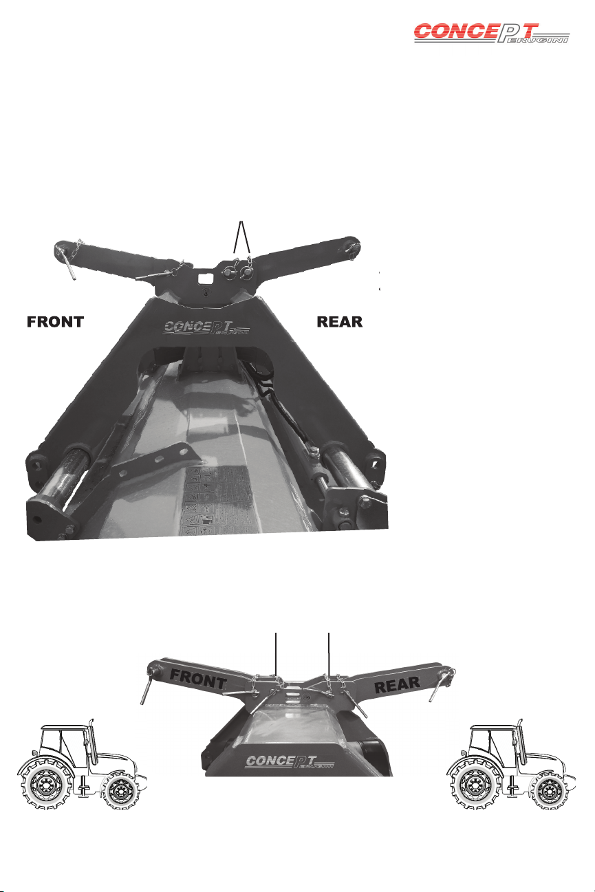
When attaching the PTO shaft to the machine and tractor make certain that if the
PTO shaft is fi tted with an overrun clutch this must be installed on the implement.
When connecting to the tractor verify that the locking pin is correctly located and
secure in place. Before use make sure all the chains and guards are correctly
fi tted.
The height of the machine from the ground is controlled by the rear roller, skids
and top link. Before using the fl ail mower make sure that the fl ails do not hit the
ground, this will result in extreme wear will damage the rotor.
Always adjust the top link to keep the machine parallel to the ground when
adjusting the height of the rear roller.
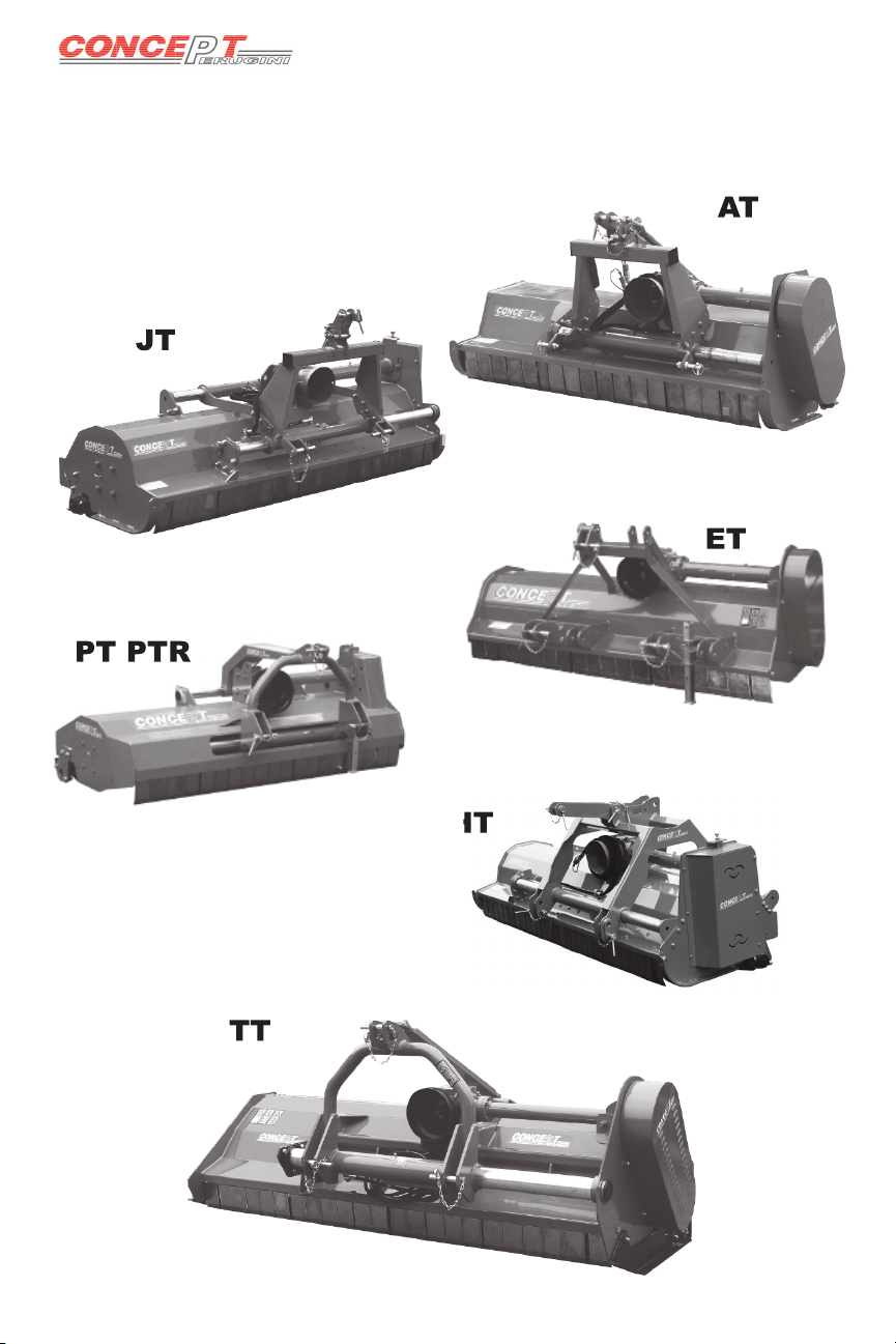
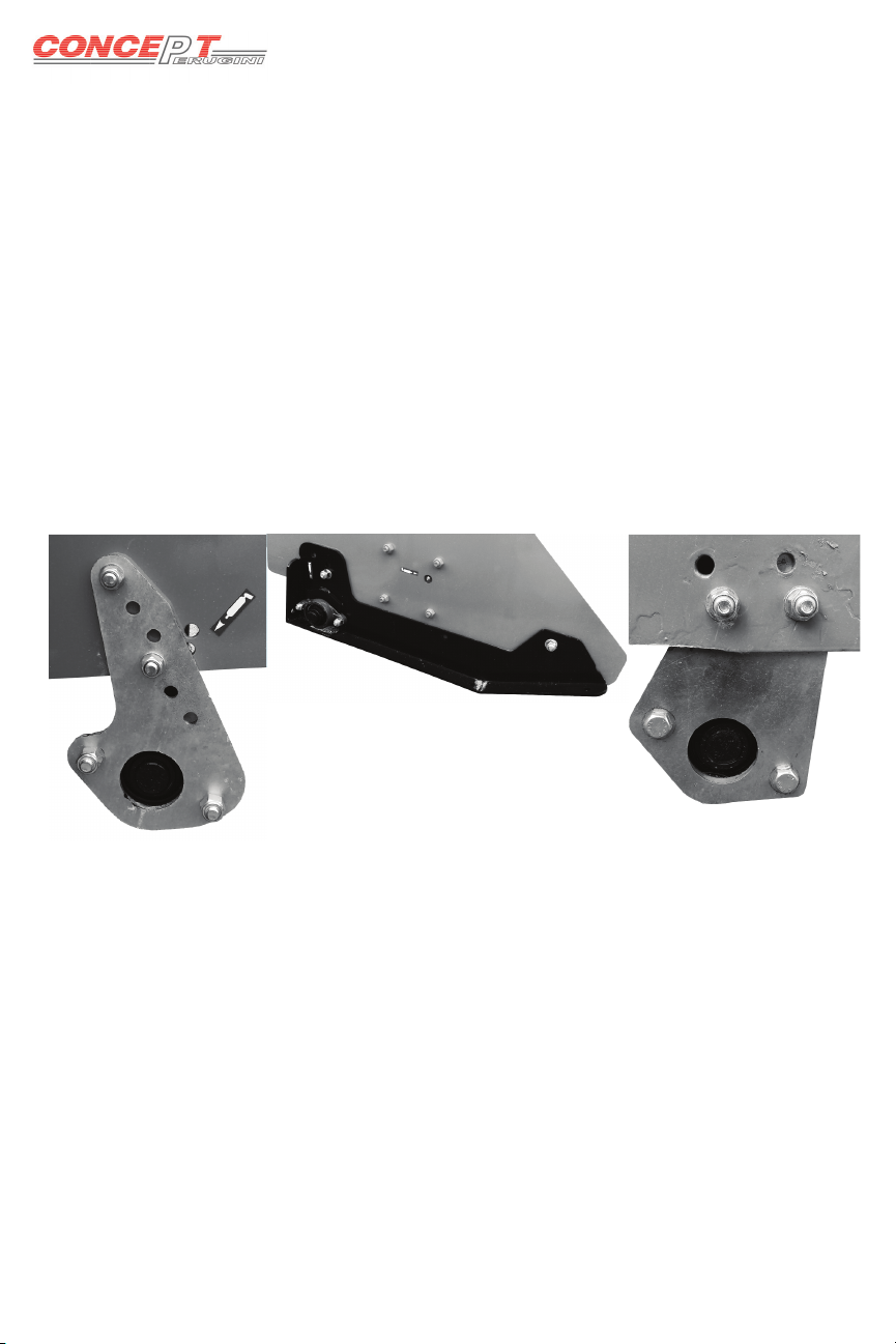
AT ET JT have the supports pictured in fi g.1 to alter the height of the roller
simply remove bolts A, position the plate so the holes align with either the higher
or lower holes on the plate and replace bolts A. On some of these models the
plates may be positioned on the inside of chassis. By moving the supports into
a horizontal position the roller can be moved further away from the fl ail rotor
allowing more space for rotor to discharge the cuttings.
TT model has the skids pictured in fi g.2 to alter simply remove bolt Band loosen
C, reposition the skid in the desired height and tighten B and C.
PT HT have the roller brackets shown in fi g.3. Undo bolts E move the plate to the
desired height and tighten bolts E. Depending on the width of the machine the
plates may be either on the inside of the chassis or the outside.
Working Depth
A
A
B
C
EE
1
2
3

11
The only machine which does not have
hydraulic side shift is the ET.
The hydraulic side shift is very simple and requires
very little maintenance, simply connect the hoses to
the tractors double acting spool valve. Make sure
there are no oil leeks and that the side shift tube is
well lubricated. Grease the grease nipple provided
every 10 working hours to reduce wear.
Side Shift
In the Field
Once the machine has been attached to the tractor, adjusted and inspected then
it can be operated in the fi eld.
• Lower the machine to approximately 10 cm from the ground.
• Engage the tractor PTO and slowly increase the speed to 540 rpm.
• Lower the machine to the ground, engage a forward moving gear and
commence forward motion.
Always drive in a straight line, when turning lift the machine off the ground
to avoid straining the parts in contact with the ground.
IF THE MACHINE IS PROVIDED WITH AN OPENING
TAILGATE, THIS CAN BE OPENED ONLY WITH THE
MACHINE STOPPED. FOR NO REASON CAN THE MACHINE
BE USED IN THE FIELD WITH THE TAILGATE OPEN.
Road Transport
When transporting on the road make sure to disconnect the PTO, if the machine
is fi tted with wheels then fold them in by relocating the pin. Carefully follow the
traffi c regulations of your country.
The only machine which does not have
hydraulic side shift is the
The hydraulic side shift is very simple and requires
very little maintenance, simply connect the hoses to
the tractors double acting spool valve. Make sure
there are no oil leeks and that the side shift tube is
Side Shift

12
Maintenance
The maintenance for the Concept Perugini fl ail mowers is very straight forward.
Lubrication
Every 10 working hours:
Grease the side shift sliding parts with Agip 33/FD or equivalent
Every 50 working hours:
Check the gear box and side shaft oil level. If necessary top up with gear oil
EP90
Every 250 working hours or once a year:
Change the oil in the gear box and the side shaft
To control the gear box
oil use cap A.
For the side shaft, check
oil level via cap Band
use plug Cto empty the
oil for the oil change.
Rotor
Maintenance on the rotor is very important.
Before and After each use check to see if the rotor
and fl ails are damaged. If the rotor is damaged it will
cause it to become unbalanced creating unwanted
vibrations which will lead to the supports breaking.
If the rotor is damaged then contact your local
dealer for either a replacement or arrange for it to be
repaired.
Check the bolts for tightness and the fl ails for wear
and breakages. Replace all broken,bent or worn
blades.
To replace the blades on the AT ET JT HT PT the
machine must be lifted and the blades replaced
from underneath, make sure the machine is properly
supported and made safe.
On the TT open the rear tailgate.
THE TAILGATE MUST BE CLOSED DURING USE,
IT CAN BE OPENED ONLY WHEN THE MACHINE
IS STOPPED AND P.T.O IS DISENGAGED
AB
C

13
Transmission
The transmission on all Concept Perugini fl ail
mowers is belt driven. After the fi rst 2/3 hours of
use check the tension in the belts via the slot on
the belt guard, there should be 5 mm play when
10kgf are applied.
Belt tension observation slot
Should the belts need tensioning or replacing,
the procedure is very simple.
A
A
B
B
C
C
AT
• Slacken the 2 nuts C
• Slacken the 4 bolts indicated A
• Adjust the tension by either tightening or
slackening bolt B, NB. Loosen the counter nuts
on Bbefore tightening or slackening
• When the belts are taught tighten the counter
nuts on Band tighten nuts C
• Move the gearbox either forwards or backwards
slightly to make the side shaft square with the
side of the fl ail mower, this is very important as
it will reduce the wear of the belts and lengthen
their life
A
ET JT HT PT
• Slacken the 3 bolts indicated C
• Slacken the 4 bolts indicated A
• Tighten or loosen bolt Bto reach the optimum
tension. NB loosen counter nut on Bbefore either
tightening or slackening
• Once the tension has been made tighten all bolts B
and C
• Move the gearbox either upwards or downwards to
make the side shaft square with the side of the fl ail
mower. This is very important in order to lengthen
the life of belts and to reduce uneven wear
B
C
Belt tension observation slot
A
B
C

14
A
C
B
TT
• Slacken nuts indicated C
• Slacken the 4 bolts indicated A which are situated under the gearbox
• Slacken the counter nuts on Band either tighten or slacken bolt B
• Once the desired tension has been made tighten all the nuts on Band
tighten nuts C
• Move the gearbox either forwards or backwards in order to make the side
shaft square with the side of the fl ail mower. This is very important as it
lengthens the life span of the belts and reduces uneven wear. Once this has
been achieved tighten bolts A
Stone Guards
The front stone guards are very important for
the protection of the tractor driver. Under no
circumstances should the machine be used without
the front stone guards. If the guards are bent, worn
or broken they should be immediately replaced,
failure to do so can result in severe injury and in
certain cases can cause death.
The picture shows the comparison between a used
worn and bent stone guard (top) and a new guard
(bottom).
If the machine is properly set up, set at the correct
height and the top tractor link is adjusted accordingly
then the stone guards should be able to hang freely
and not dig into the ground.
ALL MAINTENANCE MUST BE CARRIED OUT WITH THE TRACTOR
OFF, P.T.O DISENGAGED AND THE MACHINE PROPERLY
SUPPORTED. FAILURE TO DO SO CAN RESULT IN SERIOUS INJURY
C
B

15
Storage
Before storing the fl ail mower after it’s seasonal use it is recommended that
a thorough check and clean is carried out. Remove all dirt and address any
severely worn parts or broken parts. Treat any areas of the machine where the
paint has worn off with a rust inhibitor and store in a dry place out of the elements
to insure a longer life span. Grease the P.T.O shaft following the manufacturers
recommendations.
Spare Parts
For the correct spare parts contact your local dealer and ensure that you have
the all of the identifi cation data and correct codes of the parts required.
Always use genuine Concept spare parts
GENUINE PARTS
THE USE OF NON GENUINE SPARE PARTS WILL NULLIFY THE WARRANTY

16
Warranty
During the warranty period the appropriate maintenance should be carried failure
to do so will breach any cover necessary,
Concept Perugini S.R.L covers warranty with the exemption of wearing parts,
providing that the fault is due to defects in workmanship or material and is in
any way or to any extent not attributable to misuse, lack of reasonable care and
general wear or to the fi tting of spares, replacements or extra components which
are not supplied or approved by Concept Perugini S.R.L. failure to comply will
void warranty and should any problems a rise Concept Perugini S.R.L is not held
responsible and is not required to answer to any warranty claims.
This manual suits for next models
42
Table of contents
Other Concept Perugini Farm Equipment manuals