Serigstad MAXIFEEDER User manual

User manual
MAXIFEEDER & MAXIMAG
www.serigstad.no
We secure the forage quality and
automate heavy and time consuming
work.
Important for animal welfare, farmers
and the society.
17.12.2021
Rev.

Introduction.........................................................
Declaration of conformity..................................
Safety....................................................................
Dimensional sketch.............................................
Hazard areas........................................................
Installation............................................................
Technical data.....................................................
Connecting ..........................................................
Customization......................................................
Knife setup...........................................................
Dunctional description.......................................
Use MaxiMag.......................................................
Use MaxiFeeder...................................................
App.......................................................................
Maintenance........................................................
Troubleshooting..................................................
Spare parts...........................................................
Recycling...............................................................
Contact..................................................................
page 3
page 4
page 5-7
page 8
page 9-11
page 12-15
page 16
page 17-27
page 28-29
page 30-31
page 32-35
page 36-37
page 38-41
page 42-43
page 44-47
page 48
page 49-54
page 55
page 56
CONTENT INTRODUCTION
2

We appreciate the trust shown to our company purchasing Serigstad
MaxiFeeder/MaxiMag. The product is tested and built on a highly reliable
and known technology. The product fulll strict safety and quality
requirements.
Upon delivery our distributor will give you information about control,
maintenance and adjustments on the machine. The brief introduction is not
a compensation for the more detailed and necessary information given in
this instruction manual.
This instruction manual includes detailed safety instructions, use and
maintenance guidance, knowledge of functions and use of MaxiFeeder and
MaxiMag.
The system has one year warranty against fabrications- and material
defects. Serigstad Agri reserve the right to change the design without
obligation for previously delivered products.
We hope the product meets your expectations and needs!
Best regards
Dear customer!
Helge Njærheim
Research & Development Manager
Serigstad Agri AS
INTRODUCTION
3

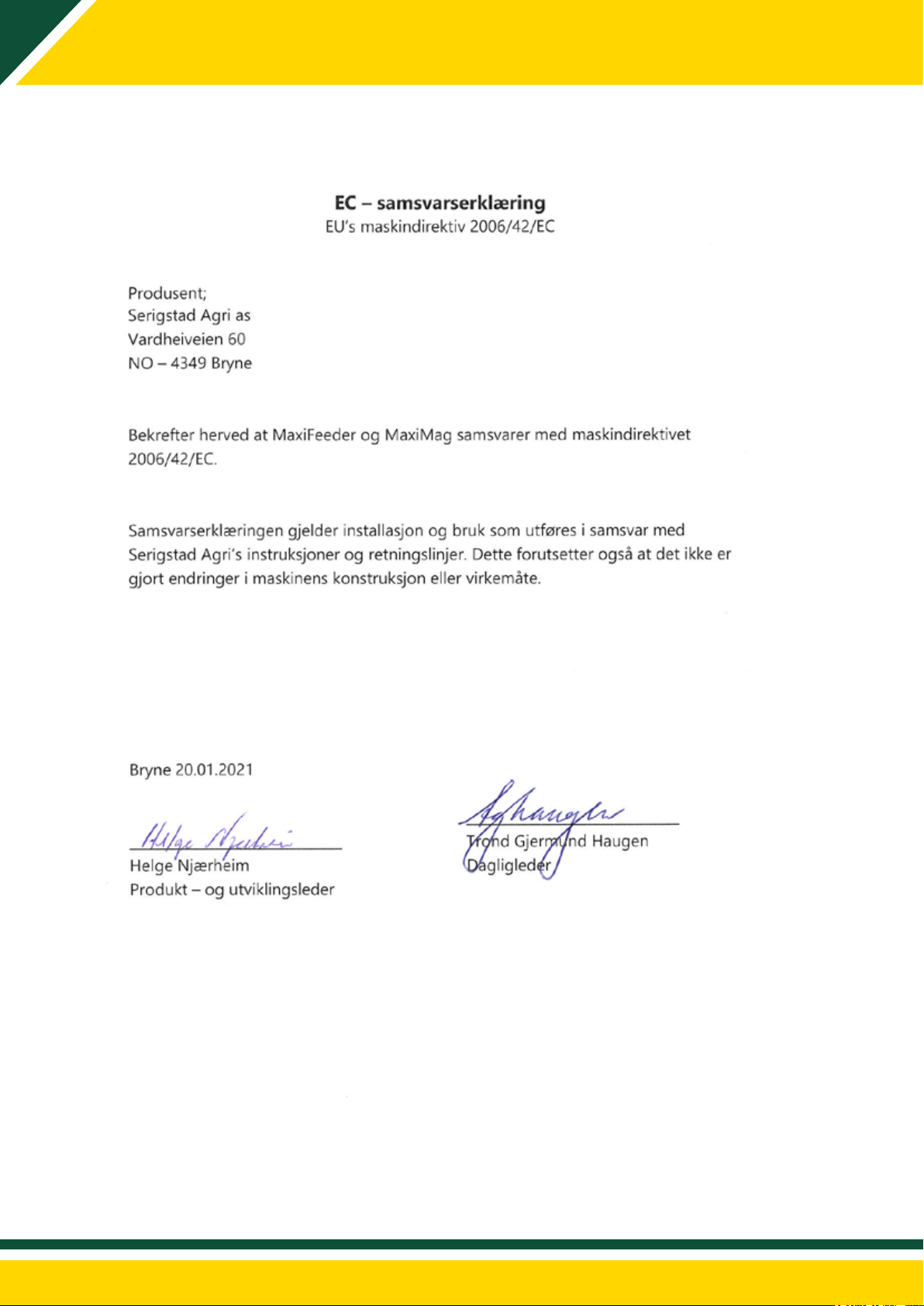
DECLARATION OF CONFORMITY
4

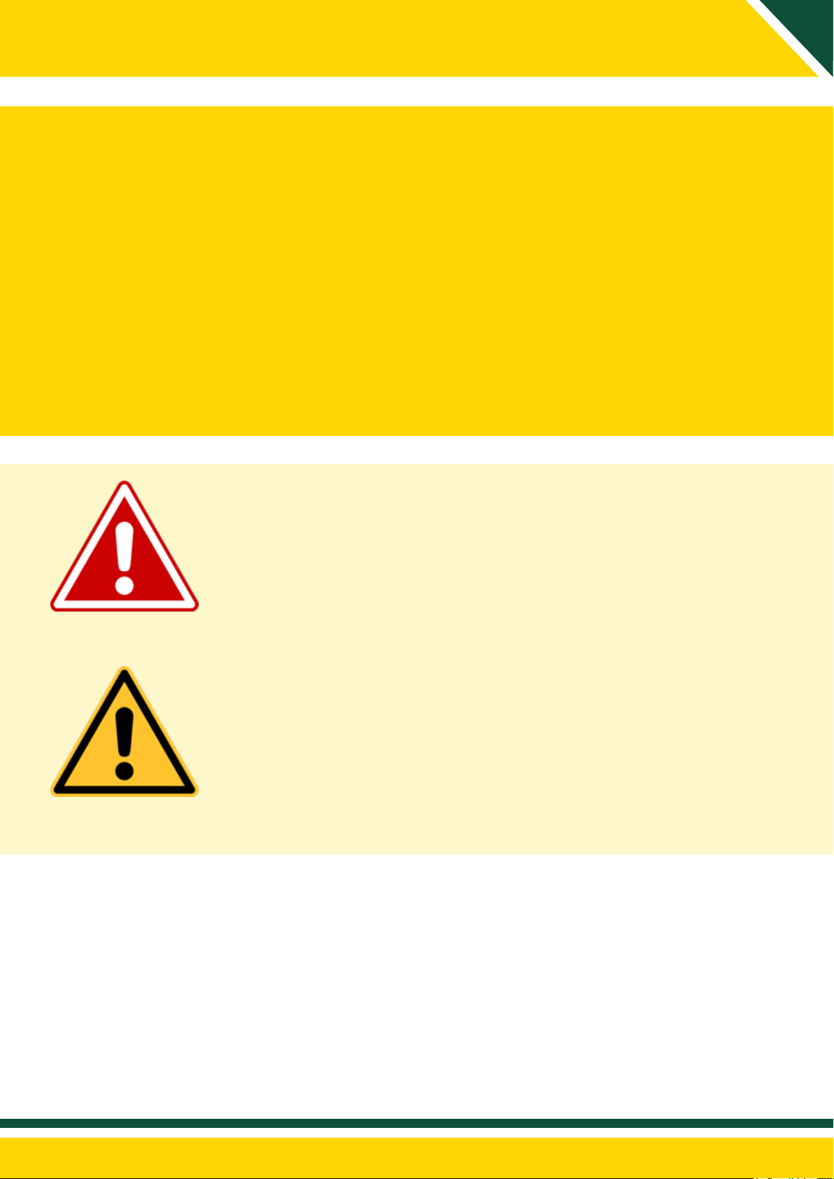
THE SYSTEM CAN BE REMOTE-CONTROLLED AND START-UP AUTOMATICALLY SEVERAL
TIMES A DAY WITHOUT SUPERVISION!
PLACE ATTACHED WARNING SIGNS VISIBLE AT THE ENTRANCE OR IN NATURAL AREA BY
THE MACHINE.
THE SYSTEM IS TO BE SECURED WITH PHYICAL BARRIERS.
SEE OUR RECCOMANDATIONS AND LEARN PRECAUTIONS FOR STAYING IN DANGER AREAS.
WARNING!
SAFETY
5
DANGER
WARNING
Indicates an imminent dangerous situation which, if not avoided,
may result in serious injury or death.
Indicates a potential dangerous situation which, if not avoided, may
result in serious injury.
The label shows exposed danger areas when he covers are opened
or removed.

6
SAFETY
Use labeled points whe lifting the machine.
Use labeled poits for lifting the machine with forklift.
Keep clear to hanging load!
WARNING! - SAFETY FIRST
Figure 1: MaxiFeeder with machine labelling
Crushing hazard, op-
erating machine can
cause serious injury
or death
Read user manual
Keep distance to
running equipment
Serial number sign
Use included lifting lugs when
lifting the machine.
Lifting lugs are disassembled
before start-up.
Covers must be
closed during
operation
Never stay in danger
area durig operation
an start-up

7
SAFETY
Description Decals
Warning sign 996760 - red and yellow zone
Warning sign 7996765 - red and yellow zone
Warning sign 996766 - red zone
Warning sign 996763 - red zone
Warning sign 996746 - red and yellow zone
Danger sign 996745 - red zone
Be careful! Make sure you read and understand the
instruction manual before startup, maintenance and
adjustments are made.
Be careful! Keep distance to running equipment. Do
not stand in hazard area during startup or operation.
Objects may be thrown out of machine during
operation.
Be careful! All covers must be closed when machine
is running. Fingers and limbs can be damaged if they
are in contact with rotating parts.
Be careful! Crushing hazard that may cause serious
injury or death! Keep distance when machine is
running.
Be careful! High voltage. Disconnect power supply
before opening control cabinet.
WARNING! Disconnect power supply before entering
high risk area for maintenance or adjustments.
Standing in danger zone during operation may cause
serious injury or death.

8
DIMENSIONAL SKETCH
Figure 2: Dimensional sketch MaxiFeeder.
Figure 3: Dimensional sketch MaxiMag.

9
HAZARD AREAS
Hazard areas must be secured!
Before startup make sure nobody stays in
hazard areas.
Before entering hazard area for maintenance,
reparations or adjustments turn o and lock
main power switch.
Red zone | 0-850mm from machine
Represents hazard area which might cause
serious injury or death. It is important
to keep safe distance to the area during
operation.
Yellow zone | 400-1000mm from machine
Representerer potensielt fareområde under
Represents potentional hazard are during
operation.
Green zone | 1000mm from machine
Represents low risk of injuries during
operation.
Figure 4: MaxiFeeder with hazard
areas.
LOW RISK AREA
LOW RISK AREA
MEDIUM
RISK AREA
HIGH RISK
AREA

10
HAZARD AREAS
SAFETY FUNCTIONS
• Emergency stop switch is placed in front of the controlcabinet and eventually SafeGuard
control cabinet.
• Lockable main power switch is placed on the left side of the control cabinet.
• Light signals:
Green: the machine has power supply.
Yellow: during start-up and operation.
Red: emergency stop is activated or fault occur.
Acoustic signal before startup.
Figure 5: MaxiFeeder with SafeGuard fences.

11
HAZARD AREAS
Height of safety fence (according to standard: EN ISO 13857:2008):
• If the machine is raised with extended leg set, the height of the safety fence must be at least
300mm higher than the lower frame on the feed table. See gure below.
• As an alternative to higher safety fences all distances of at least 850 mm can be raised to a
minimum of 1400mm.
• Minimum recommended distance from safety fence to conveyor is 600 mm, safety fence
towards the conveyor is always to be a minimum of 2000mm high.
Figure 6: For illustration: ExactFeeder with angeled chain-conveyor and fences.

12
INSTALLATION
MaxiFeeder and MaxiMag are exible machines that can be designed according to your
wishes and needs. It can be delivered as MaxiMag with only feedtable/magazine or
MaxiFeeder with cutting device for cutting and processing of forage. The system can be
delivered with up to 5 mid-sections of 2 meters each, for a total length of 14,5 meters. The
shortest unit, consists of only back- and front-section will have a total length of 4,5 meters.
Mid-sections are bolted together with splicing plates, side supports, side walls and adjusted
chain.
OBS! Control the elements are placed edge to edge without any overlap.
Figure 8: MaxiFeeder with cutting device and
two mid-sections.
Figure 7: MaxiMag with two mid-sections.
STANDARD LEG SET
Standard leg-sets on MaxiFeeder and
MaxiMag if there is no other spesications.
This leg set can be combined with a
conveyor. Lifts the machine 600 mm from
the ground.
Slide the leg into the bracket on the side of
MaxiFeeder or MaxiMag. Fasten with bolts,
nuts and support rods as shown on gure 9.
Load cells are assembled as described on
next page.
Figure 9: Assembled standard leg set.

13
INSTALLATION
STAN
The stand is assembled to the frame of the machine. The stand has lugs for assembling
supporting struts and must therefore be placed inwards toward the underside of the
machine.
The leg on the stand is prepared for adaption on site and can be cut to the required length.
To fasten the oor fastener a hole is drilled in the leg. Use the hole in the oor fastener
for steering during drilling. Bolt and counter nut are assembled in the hole to fasten the
installation. See gure below.
Figure 10:
Stand fastened to the frame.
Fastening the stand in the frame is done
with two throughout brackets which is
fastened to the stand. The stand is secured
with a supporting strut between the frame
and the leg.
The oor fastener is fastened to the
foundation with bolts.
Lug
To adapt the length of the stand cut the
legs to the required length. Floor fastener
is placed in the bottom of the stand (after
adjustment of length). Drill hole and lock the
oor fastener with bolt and counter nut. See
picture 9.
Figure 11:
Floor fastener.
Figure 12:
Short stand for machine (1) with oor fastener (2).
1
2
Bein kan kappes for tilpassing av høyde
1447,0
602
1576,0
For sikring mellom gulvfeste og bein
bores Ø 13 mm og bolt settes inn.
ITEM NO.
PART NUMBER
DESCRIPTION
QTY.
1 71235
Kort stativ for magasin
1
220290
Gulvfeste
2
Material:
Thickness:
Surface treatment:
Sheet scale:
Drawing number.
Revisjon:
Projection:
Content in:
Replaced by:
NS-1430:
Designed by:
Project:
Kort stativ magasin
1:20 71230
Helge
T5
26.02.2020
79.44
A3
Weight
Tolerance not specified according to:
Cut here for adjustment

14
INSTALLATION INSTALLATION
Figure 13:
Supporting strut fastened to the frame with bracket.
In the front of the machine bracket for
supporting strut must be placed and holes
drilled in the frame.
In the back of the machine the bracket is
placed as shown on gure 11.
Bracket
Supporting strut
To adjust angle: loosen bolts beside the
fastener for the stand.
The fastener is twisted into wanted position
and bolts fastened to lock the position.
Figure 14:
Fastening of stand to frame.

INSTALLATION INSTALLATION
15
LOAD CELL
MaxiFeeder with cutting device has a load cell
installed in each leg to measure the forage amount
which goes through the machine.
The load cells are placed on a ball to remove side
circuits. These balls are placed after the legs are
assembled. After installation calibrate load cells in
the setup menu with empty chamber.
See page 38 for fullling information about
calibrating load cells.
1. Place the machine in position. Load cells are delivered balanced
without ball to prevent damage on the load cells during
transportation.
2. Make sure the machine rest on the assembling jigs cone, to prevent
side circuits on the load cells. Fasten the base to the fundament.
3. Place ball in the groove on the base.
4. Fasten bolt to the machine lifts a couple of millimetres and thereby
rests on the ball. Make sure the ball is placed correctly between the
base and bolt.
Figure 15: Load celll assembled
into leg.
Figure 16:Cross-section of supported
ball in load cell. The assembling jig is
shaped with a cone which centre ball.
Figure 17: Leg set with load cells.
1
2
3
ITEM NO.
PART NUMBER
DESCRIPTION
QTY.
1 71085
Kombifot 1 med veiecelle
1
2
Mirror 71085
Kombifot 1 med veiecelle
1
371043
Stag for stativ matebord
2
Material:
Thickness: Surface treatment:
Sheet scale:
Drawing number.
Revisjon:
Projection:
Content in:
Replaced by:
NS-1430:
Designed by:
Project:
Kpl. beinsett 1 f. veieceller
1:20 71090
Helge
Helge
Serigstad Agri AS
T1
Exactfeeder
12.10.2018
A3
Weight
Tolerance not specified according to:
1
2
3
ITEM NO.
PART NUMBER
DESCRIPTION
QTY.
1 71085
Kombifot 1 med veiecelle
1
2
Mirror 71085
Kombifot 1 med veiecelle
1
371043
Stag for stativ matebord
2
Material:
Thickness: Surface treatment:
Sheet scale:
Drawing number.
Revisjon:
Projection:
Content in:
Replaced by:
NS-1430:
Designed by:
Project:
Kpl. beinsett 1 f. veieceller
1:20 71090
Helge
Helge
Serigstad Agri AS
T1
Exactfeeder
12.10.2018
A3
Weight
Tolerance not specified according to:
Figure 18: Detail leg.

16
TECHICAL DATA
Figure 19: MaxiFeeder with motors.
MOTOR KNIFEDRUM
9,2 kW
1450 RPM
Gear transmission: 1:9,69
Shaft/bearing: 40 mm
MOTOR CONVEYOR BELT
0,25 kW
1380 RPM
Gear transmission: 1:821,70
Shaft/bearing: 40 mm

17
CONNECTING
CONTROL CABINET
The control cabinet is complete and assembled from the factory. The placing of the control
cabinet is spesied when ordering.
Connecting:
• Power supply for control cabinet
• Startup signal from superior control/software
Signal for external startup of MaxiMag on input 19+20.
CONNECTING MAXIFEEDER AND TOPFEEDER
To control MaxiFeeder via TopFeeder use following setup:
Signal on input 11 Startup machine and running knifedrum
Signal on input 12 Pause mode canselled, conveyor belt can start
MaxiFeeder receeive startup signal when TopFeeder starts on input 11.
Machine starts with acoustic signal before startup. Knife drum runns.
When the machine receive signal on input 12 conveyor belt starts, feeding will thereby start.
When signal on input 12 ceases, the machine will go into pause mode where only kutting
device run, but forage will not be drawn to the drums.
This function is useful in combination with for instance TopFeeder where it is desirable to
pause the feeding while replacing the plow between the dierent groups, without stopping
the machine completely.
The signal can in sometimes be permanently xed to always feed when signal 11 is activated.
MAXIFEEDER OG MAXIMAG IS DELIVERED IN 230V OR 400V
MaxiFeeder use a control cabinet with more advanced software while MaxiMag has a control
cabinet with a more
Two motors for conveyor belt is used when there are three or more midsections.
Technical data Motor size 230V 400V
Knife drum 9,2kW 29,5 A 17,5 A
Conveyor belt 0,25kW 1,4 A 0,74 A
Conveyor belt 2 0,25kW 1,4 A 0,74 A
Reccomended fuse size 3 faser + jord for 230V
3 faser + null + jord for 400V Min. 35A Min. 25A

18
CONNECTING MAXIFEEDER
No. Explanation Control Cabinet
1Rectier
2 PLC
3 Motorprotector
4 Fuse
5 Main power switch
6 Power supply
No. Explanation Control Cabinet
7 Terminal block
8 Safety relay for emergency stop
9 Frquensy converter
10 Input- /output- signal
11 Emergency stop circuit
NOTE!
All connecting must be performed by authorized personal.
Installed and tested control cabinet from factory.
Figure 20: MaxiFeeder control cabinet.
9
5
4
3
1
8
2
6 7 10 11

19
CONNECTING MAXIFEEDER

20
CONNECTING MAXIFEEDER
This manual suits for next models
1
Table of contents
Other Serigstad Farm Equipment manuals