Sertain S4540 Installation guide

Operating & Care
Instruction Manual
S4540/S4545
HI-LO Pressure Care Chairs

DO NOT USE CHAIR UNTIL YOU HAVE FULLY READ THE INSTRUCTIONS
SAFETY WARNING
This manual MUST be read and understood before use of this product.
»The electrical system of this chair is designed to be used with a 240V power source when supplied in Australian
format. Ensure you have been supplied the correct format.
»Do not allow the battery back-up system to fully discharge before connecting to mains supply where this
accessory is tted.
»Do not continue to operate the handset by repeatedly pressing the buttons if any of the functions will not
move.
»Do not continually operate the chair functions. Doing this may cause the thermal fuse in the control box to cut
o power.
»Do not force the operation of any part of the chair. Doing so may cause damage. Refer to the manual for
correct operation of the chair.
»Keep the chair away from any source of open ame.
»Do not use the system in the presence of ammable gases (such as anaesthetic agents). We recommend that
this system is used under the guidance of a healthcare professional.
»The use of this system is only part of an overall care plan. The patient must still be re- positioned regularly.
»The control unit should only be serviced by authorized personnel. Return to your authorized distributor for
repair.
»Switch o the electrical supply to the chair and disconnect from power source before cleaning and inspection.
»Brakes must be applied when transferring client into or out of chair and when not in use.
»Chairs are designed to be used on smooth, level paved areas.
»This chair must not be used for transport of a client in a taxi vehicle.
»The Backrest and Leg rest must not be sat on. Doing so may seriously damage the chair.
»Care should be exercised that power cords are not in the way of any mechanism or moving parts.
»Any damaged, worn, broken or non-functioning parts should be reported and repaired. If client or carers safety
is at risk, the unit should be withdrawn from service until repaired and safe for use.
»Communication: Carers must always inform other carers, the client and any other person in the vicinity, when
positioning, transporting or using any of the chairs functions.
»Never operate this chair while under the inuence of alcohol or any other substances that could detract from
your alertness or physical and intellectual acuity.
»This chair must not be used by more than one occupant at any time or for carrying any other loads.
»CHILDREN MUST NOT be allowed to operate chair or controls AT ANY TIME. Any child in the vicinity of the
chair MUST BE SUPERVISED AT ALL TIMES.
»For any information on the Electrical System please turn to Section 5 – Technical Data.
»Make sure patient/user has been positioned correctly back on backrest, bottom on seat, legs on legrest.
»WARNING: DO NOT LEAVE CLIENT UNATTENDED, ESPECIALLY WHILE SEAT IS RAISED!
»WARNING: IF YOU ARE UNSURE OF SUITABILITY OF USE FOR ANY PATIENT, USER OR CARER, IMMEDIATELY
DISCONTINUE USE.
NOTICE
This manual does not override the OH&S Policy of any organisation using this product.
Please refer to your organisation’s OH&S Policy before using this product.
2 © 2019Careleda M-03 WI-204rev 6 Edited 29.10.2019

DO NOT USE CHAIR UNTIL YOU HAVE FULLY READ THE INSTRUCTIONS
1. INTRODUCTION
2. PRODUCT DESCRIPTION
»Electrically operated reclining backrest.
»Electrically operated seat tilt.
»Electrically operated height adjustment.
»Electrically operated leg rest adjustment
(includes spline function).
»Fold out padded footrest.
»Extendible footrest.
»Removable arms (range available).
»Swing-away 3-position head wings (S4540 model).
»Pressure area management seating system.
»Adjustable headrest cushion.
»Will lie in the supine position.
»Maximum weight capacity – 160kg (STD),
300kg (Large) & 350kg (Extra Large).
»150mm castors.
»Emergency battery back-up system.
The Sertain S4540/S4545 Series Hi-Lo Series Pressure Care Chair range provides comfort, assistive pressure care
(via adjustability and positioning) and exibility for those who are mobile / immobile, at risk of developing pressure
sores, and who spend a large part of their day sitting or lying down. It is both Client and Carer friendly, being used in
some procedural and intensive care environments (model depending and subject to suitable assessment).
Thank you for choosing another quality Sertain Product. This manual is your guide to operating,
cleaning and routine maintenance of the Sertain S4540 & S4545 Series Hi-Lo Pressure Care Chairs. It must
be kept with the chair at all times.
Section Contents Page
0 Safety Warnings 2
1 Introduction 3
2 Product Description 3
3 Operating Instructions 4-11
4 Assistance and Tips 12-13
5 Technical Data 14-26
6 Trouble Shooting Procedures 27
7 Cleaning and Maintenance 28-32
3
© 2019 Careleda M-03 WI-204rev 6 Edited 29.10.2019
DO NOT USE CHAIR UNTIL YOU HAVE FULLY READ THE INSTRUCTIONS
3. OPERATING INSTRUCTIONS
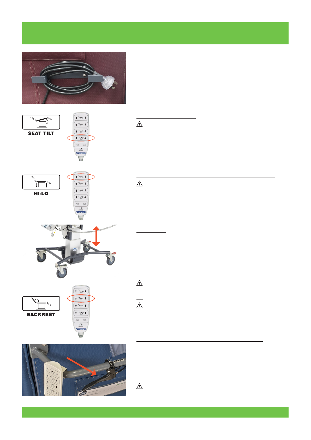
3.1 Power Cord Use and Storage - See diagram
When not in use, the power cord is stored, as shown in Figure 1. To charge
the chair batteries, park chair near to a power source, un-wrap the power
cord, plug it into power source and switch on power. Ensure that the
chair and cord are not left in an unsafe/hazardous position. Follow your
organizations policy on the use of power cords. Always STOW cord before
moving chair.
3.2 Seat Tilt Adjustment
Before tilting seat make sure it is safe to do so, make sure the client/
patient and the carer are safe and the client is positioned correctly. Also
make sure that no items, (equipment etc.), are placed over or under any
part of the chair before operating this feature.
Tilt chair to desired position by depressing the left or right hand buttons
on the handset either side of the SEAT icon as shown in Figure 2.
3.3 Seat Height Adjustment (for models with this feature)
Before adjusting seat height make sure it is safe to do so, make sure
the client/patient and the carer are safe and the client is positioned
correctly.
Note: It is best to maintain this function, chair power cord should be
connected to power supply. Power cord must be unplugged from power
supply and stowed carefully on chair before transporting client or
moving chair.
To Raise Chair
Make sure that no items, (equipment etc.), are placed over the chair.
Raise the chair to the desired height by depressing the correct buttons on
the handset either side of the HILO icon. HILO icon as shown in Figure 3.
To Lower Chair
Make sure that no items, (equipment etc.), are placed under the chair.
Lower the chair to the desired height by depressing the correct buttons
on the handset either side of the HILO icon as shown in Figure 3.
CLIENT/PATIENT must not be left unattended when seat is RAISED.
3.4
Before adjusting backrest, make sure it is safe to do so, make sure the
client/patient and the carer are safe and the client is positioned correctly
including limbs, clothing, etc. Make sure no item (equipment, persons,
etc.) obstruct the path of the backrest, to prevent injury to client or carer,
and also prevent damage to your chair.
Back Rest Adjustment – Electric (for models with this feature)
Adjust backrest to desired position by depressing the left or right hand
buttons on the handset either side of the Back Rest icon as shown in
Figure 4.1.
Back Rest Adjustment – Manual (for models with this feature)
Adjust backrest to desired position by supporting the backrest and
operating the hand lever located on the push handle – refer to Figure 4.2
CLIENT/PATIENT/ANY PERSONS must not sit on backrest or at any
time egress over the backrest when it is reclined.
Figure 1
Figure 2
Figure 3
Figure 4.1
Figure 4.2
4 © 2019Careleda M-03 WI-204rev 6 Edited 29.10.2019

DO NOT USE CHAIR UNTIL YOU HAVE FULLY READ THE INSTRUCTIONS
3.5 Swing Away Head Wings - (Models with this feature)
Make sure client/patient and carer are safe and client is positioned
safely.
Refer to Figure 5 - While applying light pressure on head wing at ‘C’
lift at ‘D’ and swing the wing outwards and relocate into the desired
position. To return to the original position reverse this procedure.
Assess need for brakes to be engaged.
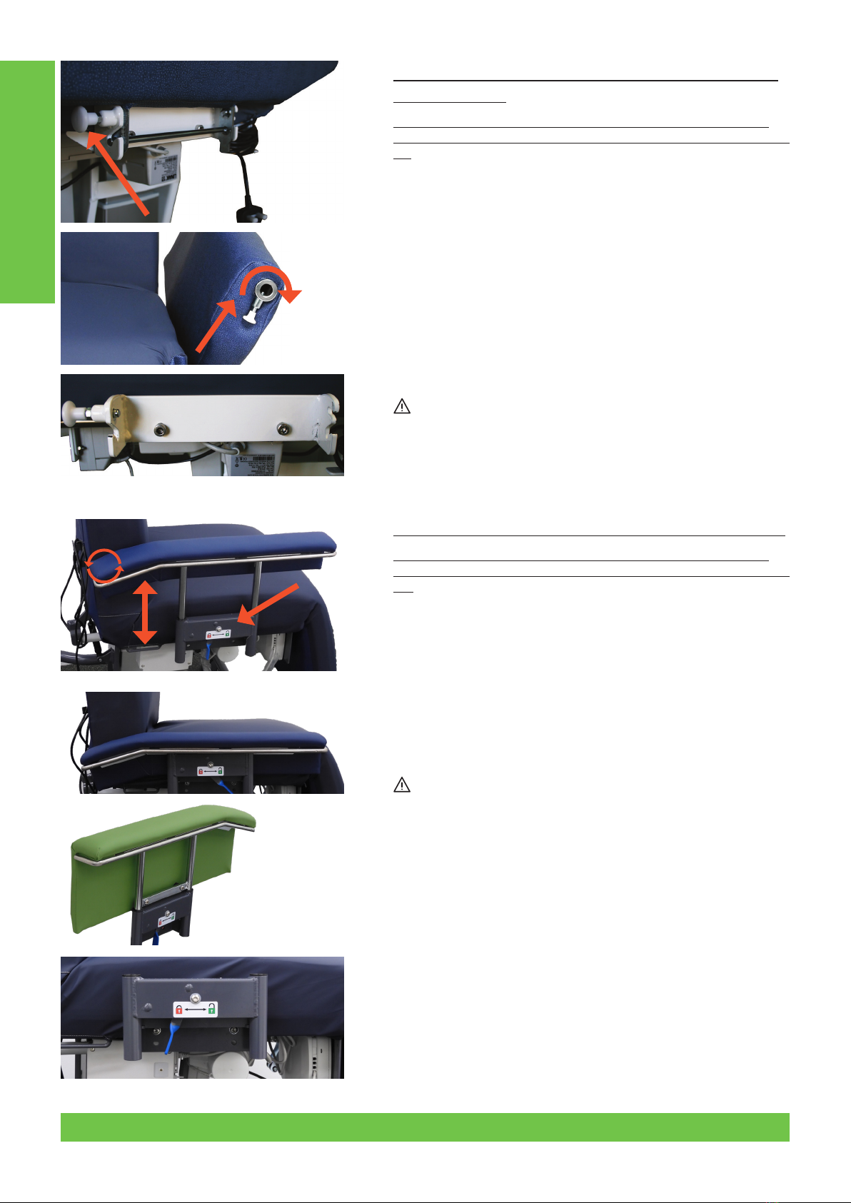
3.6.1 Removable 2- Position Armrest - (Models with this
feature)
First make sure that the brakes are applied and client/patient and
carer are safe and client is positioned safely, including limbs, clothing,
etc.
To operate 2 position feature – refer to Figure 6.1 - pull and hold the
white release knob found near the front of the arm (down at the pivot
bracket), and rotate the arm away from the chair. Release the knob
and the pin will drop into the 2nd position (23°) as the arm is rotated.
To return to the original (standard) position, reverse this process.
Operating Instructions
Figure 5
Figure 6.1
C
D
5© 2019 Careleda M-03 WI-204rev 6 Edited 29.10.2019
DO NOT USE CHAIR UNTIL YOU HAVE FULLY READ THE INSTRUCTIONS
3.6.4 Drop-arm / Procedure Arm - (Models with this feature)
First make sure that the brakes are applied and client/patient and
carer are safe and client is positioned safely, including limbs, clothing,
etc.
To lower armrest:
Type 2 – Move the lever in the desired direction i.e. Unlock – refer to
the label - See Figure 6.5 – and then push armrest down until it can go
no further.
To raise armrest:
Type 2 – Move the lever in the desired direction i.e. Unlock – refer to
the label - See Figure 6.5 – and then lift armrest up until the locking
mechanism automatically clicks into place. Test the arm to make sure
it is locked and cannot come out inadvertently.
Make sure armrest is securely fastened before leaving the chair.
3.6.3 Removable 2- Position Armrest – Style No.2 - (Models
with this feature)
First make sure that the brakes are applied and client/patient and
carer are safe and client is positioned safely, including limbs, clothing,
etc
To remove armrest - rst pull and hold the white release knob (see
arrow in Figure 6.3) and at the same time with the other hand swing
the armrest down. When the arm stops, let go of the release knob.
Then hold the armrest with both hands, lift it up slightly and then pull
out and away from the side of the chair.
To replace armrest – while holding the armrest with both hands,
line up the front and rear pivot points within the slots of the armrest
bracket. Slide the arm down into this slot as far as you can go, and
then rotate the armrest up towards the chair. The release pin at the
front of the retaining bracket should automatically allow the armrest
to move past it and then it will snap into the 2nd position location.
Pull and hold the white release knob and rotate the arm further
upward until the arm is in the 1st or standard position.
Make sure armrest is securely fastened before leaving the chair.
NOTE: FOR SAFETY REASONS THE ARMRESTS WILL NOT FOLD UNDER
THE CHAIR
Operating Instructions
Figure 6.3
Figure 6.4
Procedure Arm
(lift o only)
Figure 6.5
6 © 2019Careleda M-03 WI-204rev 6 Edited 29.10.2019
DO NOT USE CHAIR UNTIL YOU HAVE FULLY READ THE INSTRUCTIONS
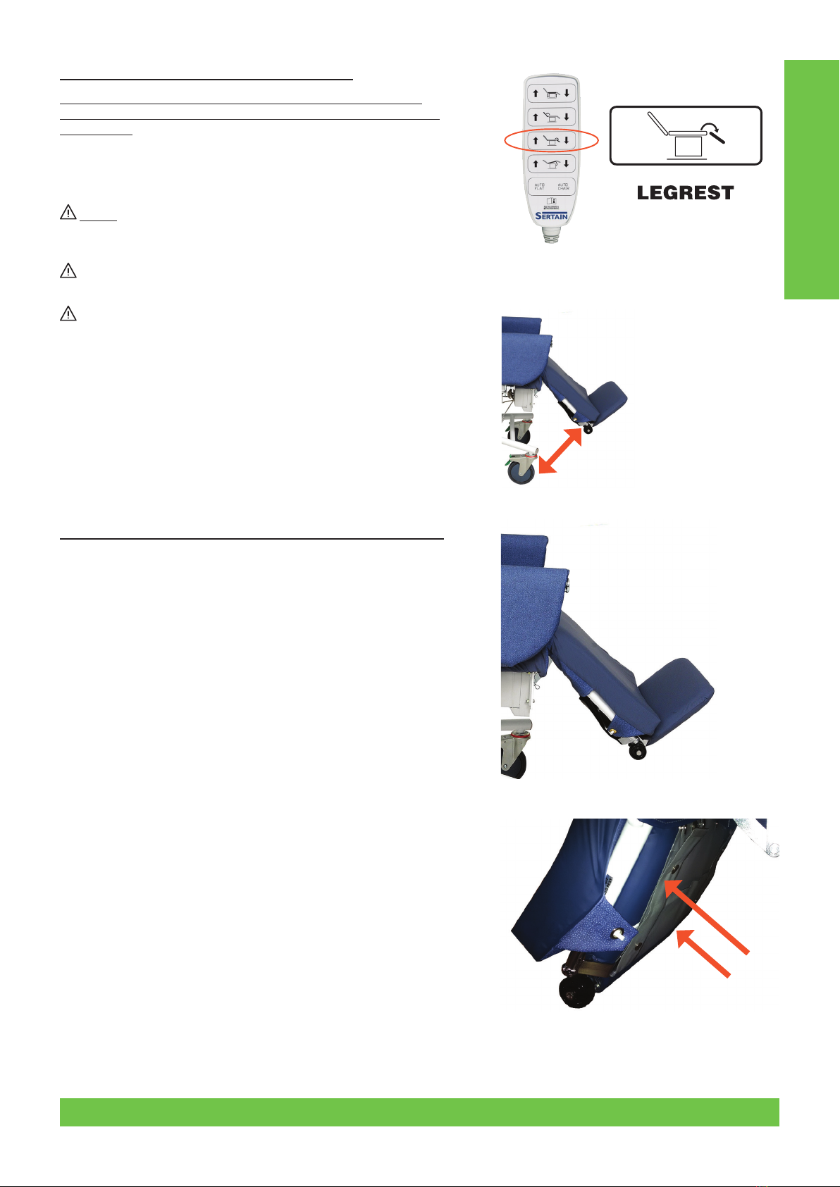
3.7 Leg Rest Adjustment – Standard & Deluxe
Before adjusting leg rest, make sure it is safe to do so. Make sure
client/patient and carer are positioned safely and castors are out of
legrest path.
Adjust Leg Rest to the desired position by depressing the left or right
hand buttons on the handset either side of the Leg Rest icon as shown
in Figure 7.
Before lowering leg rest to forward transfer the client, or when
using the stand-up lifter, Footrest must rst be folded down under leg
rest cushion. See Section 3.9 for instructions.
Make sure no item (equipment, persons, etc.) obstruct the path of
the leg rest.
Client/patient must not sit or weight bear on the legrest at any
time and must not egress over the leg rest when it is up (this includes
partial elevation). Leg rest must be fully retracted before forward
transfer is performed!
3.8 Leg Rest Length Adjustment - (Models with this feature)
Type 1 - Unfasten the three ‘hook and loop’ straps from the underside
of leg rest at Figure 8.1 – shorten or lengthen leg rest to desired
position by sliding the footrest and its support in or out of the leg rest,
and re-fasten straps. Always make sure the ‘hook and loop’ straps
have been fully re-fastened.
NB: the footrest can be in the ‘Away/Closed’ position when
performing this function.
Type 2 - Unfasten the two ‘Press Stud closure retaining straps’ from
the underside of leg rest at Figure 8.2 – shorten or lengthen leg rest
to desired position by sliding the footrest and its support in or out of
the leg rest, and re-fasten straps when the desired position is reached.
Always make sure the ‘retaining straps’ have been fully re-fastened.
NB: the footrest can be in the ‘Away/Closed’ position when
performing this function.
Operating Instructions
Figure 7
Figure 8.1
Figure 8.2
Deluxe
Leg Rest
7© 2019 Careleda M-03 WI-204rev 6 Edited 29.10.2019
DO NOT USE CHAIR UNTIL YOU HAVE FULLY READ THE INSTRUCTIONS
3.9 Fold-Out Footplate - (Models with this feature)
Make sure the client is correctly positioned. Unhook Cover eyelet at
Figure 9.1 on both sides of the chair. Lift padded leg rest cushion only and
then fold out footrest (see Figure 9.2). Cover tag eyelets (Figure 9.1) must
then be re-hooked.
Before lowering leg rest, to forward transfer the client, or when using
the stand-up lifter, Footrest must be folded away/down under leg rest
cushion.
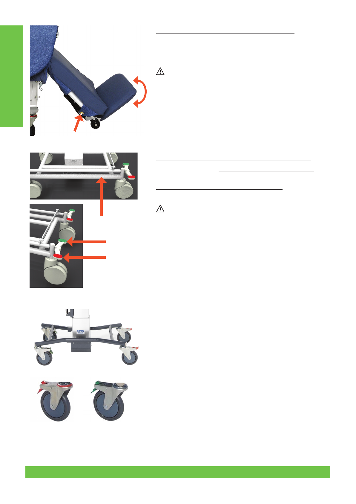
3.10 Central Locking Castors - (Models with this feature)
Brake - Press down on the left side (or Red) pedal to activate brake.
Directional Lock (tracking/steering) - Press down on the right side
(or Green) pedal to activate tracking/directional lock.
Neutral - Mid-position is neutral.
Make sure you have the castors fully engaged in BRAKE position
before any procedure.
3.11
Operate tracking castors - (Models with this feature)
Refer to Figure 11.2 - Swing castor into position parallel with side frame.
Press down green/silver tab and click into position. To disengage press
top of green/silver tab. Tracking position needs to be engaged whenever
the leg rest is down.
Activate brakes - (Models with this feature)
Refer to Figure 11.1 - Individual brakes on rear castors; to engage, press
down red/silver tab. To disengage, press top of red plastic tab.
Operating Instructions
Figure 9.1
Figure 10
Figure 11.1 Figure 11.2
Figure 9.2
8 © 2019Careleda M-03 WI-204rev 6 Edited 29.10.2019

DO NOT USE CHAIR UNTIL YOU HAVE FULLY READ THE INSTRUCTIONS
3.12 Auto Chair Function - (Models with this feature)
WARNING:
Before using this function, make sure it is safe to do so. Make sure no
item (equipment, persons, etc) obstruct the path of any moving part
of the chair during this function. Warn all persons before actioning
this function.
This is an automatic chair position function – to operate, press and
hold the ‘Auto Chair’ button, as indicated in Figure 12 (bottom right
corner of handset button series). While holding this button (from
any existing position), the chair will operate the backrest, seat tilt,
hi-low, and leg rest functions simultaneously until the chair position
is reached (Hi-Lo will be at its lowest height). Once this position is
reached and all motors have stopped then release the button.
Release of the button before the chair has reached the pre-set sitting
position, will stop all functions wherever they are at the time. The
chair will not continue to operate automatically. Resuming pressure
on the button will continue the function.
3.13 Auto Flat Function (this is not a CPR facility) - (Models
with this feature)
WARNING:
Before using this function, make sure it is safe to do so. Make sure no
item (equipment, persons, etc) obstructs the path of any moving part
of the chair during this function. Warn all persons before actioning
this function.
This is an automatic Bed / Lay Flat position function – to operate,
press and hold the ‘Auto Flat’ button, as indicated in Figure 13
(bottom left corner of handset button series). While holding this
button (from any existing position), the chair will operate the
backrest, seat tilt, hi-low, and leg rest functions simultaneously until
the bed/lay at position is reached (Hi-Lo will be at its lowest height).
Once this position is reached and all motors have stopped then
release the button.
Release of the button before the chair has reached the pre-set bed/
lay at position, will stop all functions wherever they are at the time.
The chair will not continue to operate automatically. Resuming
pressure on the button will continue the function.
Operating Instructions
Figure 12
Figure 13
9© 2019 Careleda M-03 WI-204rev 6 Edited 29.10.2019
DO NOT USE CHAIR UNTIL YOU HAVE FULLY READ THE INSTRUCTIONS
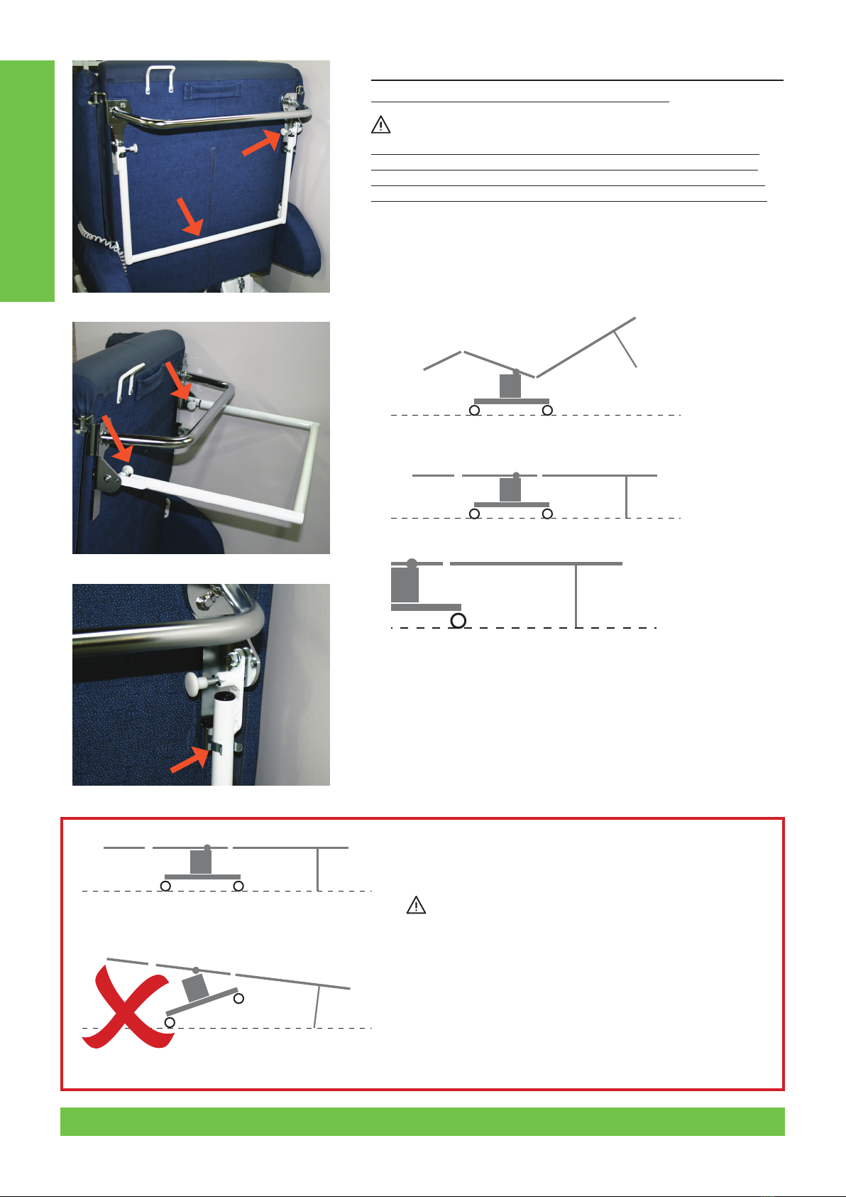
3.14 Lay Flat Support Bar Function – for backrest support when
performing procedures (if tted to your chair)
WARNING 1
Before using this function, make sure it is safe to do so. Make sure no
item (equipment, persons, etc) obstructs the path of any moving part
of the chair during this function. Warn attendees before actioning this
function. This item is NOT a push handle and is not to be used as such).
TO ENGAGE:
Lift / swing out the Support Bar at 14a.1 (see Figure 14a) until it is 90°
to the backrest. Make sure both locating Pins at 14a.2 are locked with
the Support Bar at 90° to the Backrest. Now you may perform ‘Auto Flat
Function’ (see Item 3.13).
TO RELEASE AND STORE:
Release Pins at 14b.1 (see Figure 14b) and lower Support Bar till it is
held by retaining Clip at 14c.1 (see Figure 14c). Make sure the locating
Pins are engaged ready for the next event.
For safety the chair should not be left in this position after procedure
is completed.
Raise backrest rst and restow. Check there is no damage done to the
CPR unit after use.
WARNING 2
When the chair is in, or close to complete LAYFLAT position
(when performing Function Item 3.13) the SEAT TILT, Item
3.2 MUST NOT BE ACTIVATED or Figure 14e could occur,
endangering persons or equipment.
Operating Instructions
Figure 14a
14a.1
14b.1
14c.1
14a.2
Figure 14b
Figure 14c
Figure 14d
Figure 14e
10 © 2019Careleda M-03 WI-204rev 6 Edited 29.10.2019
DO NOT USE CHAIR UNTIL YOU HAVE FULLY READ THE INSTRUCTIONS
CPR WARNING:
If you or your facility decides to use this chair for CPR purposes, it is only to be performed if the chair has a
LAY FLAT SUPPORT BAR (see Section 3.14) tted to manufacturers’ specications and the bar is at 90 o (degrees) to
the BACKREST and the FLOOR – see following conditions.
In the event you need to perform CPR on a client in this chair you must have fully read and understood everything on
this document and the following must be strictly adhered to;
1. If you have a LAY FLAT SUPPORT BAR – SWINGDOWN STYLE it must be fully engaged FIRST (see Section 3.14 &
Figure 14a)
2. Then fully activate AUTO FLAT SYSTEM (see Section 3.13 & Figure 13).
3. You have assessed the need for a CPR assistance device such as a CPR board which may be required for eective
CPR due to the Pressure Care Seating system in use on this chair. Your clinical team needs to assess this as
the manufacturer provides the chair with multi-positioning outcomes but cannot guarantee or advise on the
eectiveness of the patient outcomes from a CPR event due to a multitude of external factors.
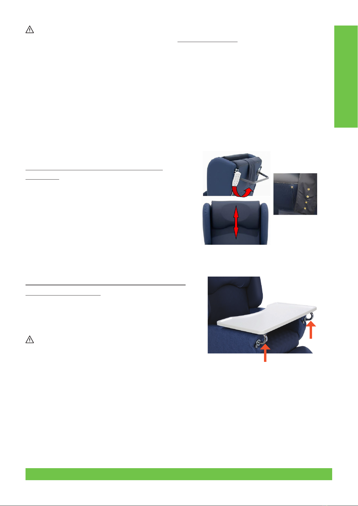
3.15 Headrest Cushion Adjustment - (Models with
this feature)
Raise or lower headrest cushion to desired position by adjusting the
headrest ap via the fastening system (see gure 15).
3.16 Fitting Sliding Activity Tray (Models with this feature)
Apply brakes before tting tray.
Tray locating lugs are situated on front of the chair arm underneath
the tray retaining tube.
Disengage locating pins (pull pin down and ¼ turn), slide the table
arms into desired position, engage locking pins (¼ turn in reverse).
NOTE: If tray is to be locked make sure pins are located and locked
securely for client and carer’s safety and that you have any
relevant approvals for use of this type of device.
Operating Instructions
Figure 15
11© 2019 Careleda M-03 WI-204rev 6 Edited 29.10.2019
DO NOT USE CHAIR UNTIL YOU HAVE FULLY READ THE INSTRUCTIONS
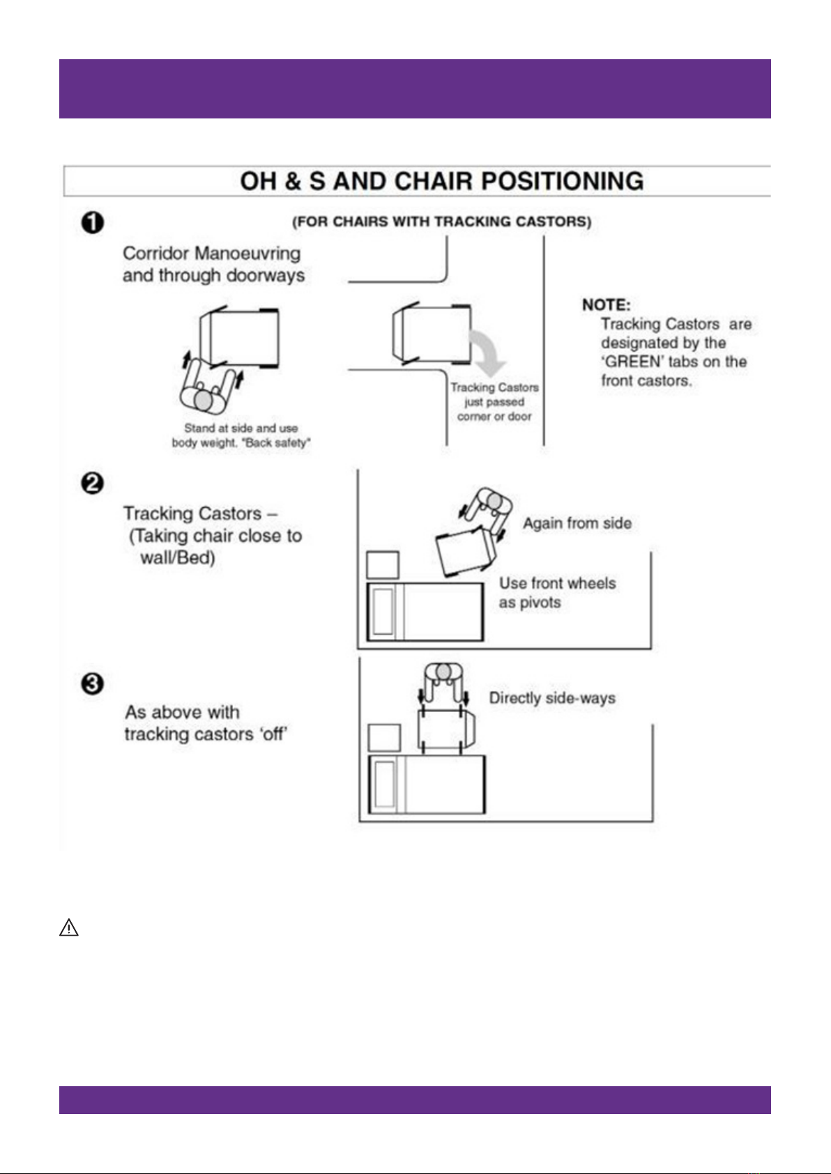
NOTE: REMEMBER!! In any manoeuvre, the safety of the Client and Carer is paramount.
This is only a guide and does not take the place or override your OH&S training or Client handling techniques. This must be
approved by those responsible persons in your organisation before use.
E & OE
4. ASSISTANCE & TIPS
12 © 2019Careleda M-03 WI-204rev 6 Edited 29.10.2019

DO NOT USE CHAIR UNTIL YOU HAVE FULLY READ THE INSTRUCTIONS
NOTE: REMEMBER!! In any manoeuvre, the safety of the Client and Carer is paramount. This is only a guide and does not take the
place or override your OH&S training or Client handling techniques. This must be approved by those responsible persons in
your organisation before use. E & OE
Assistance & Tips
13© 2019 Careleda M-03 WI-204rev 6 Edited 29.10.2019
DO NOT USE CHAIR UNTIL YOU HAVE FULLY READ THE INSTRUCTIONS
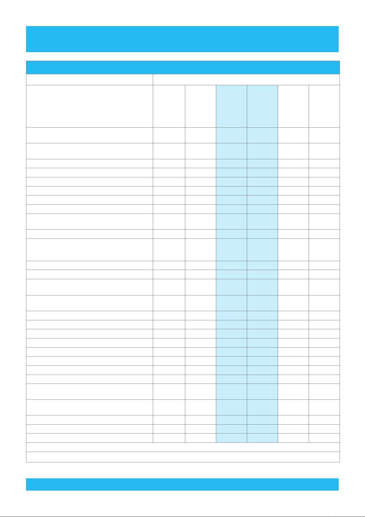
5. TECHNICAL DATA
5.1 GENERAL TECHNICAL DATA
DESCRIPTION MODEL
Please note that your particular model may
have some of the features listed and not
o t h e r s , d e p e n d i n g o n t h e c o n g u r a t i o n c h o s e n .
The list of technical specs. Below is not exhaustive,
and if you require any further information please
contact the Company that sold the chair to you.
S4540
STD SIZE
S4540
LGE SIZE
S4540
XL SIZE
S4545
STD SIZE
S4545
LGE SIZE
S4545
XL SIZE
Armrest Height (Drop Down type) – at hips
(from seat cushion)
190 190 190 190 190 190
Armrest Height (Standard removable type) – at
hips (from seat cushion)
160 160 160 160 160 160
Auto Chair ü üüüüü
Auto Lay-Flat ü üüüüü
Backrest – Height (from seat cushion) 730 730 730 730 730 730
Backrest – Recline Range 96° - 180° 96° - 180° 96° - 180° 96° - 180° 96° - 180° 96° - 180°
Backrest – Width at Shoulders 560 660 760 570 670 770
Castors – Central Locking 150mm type available available available available available available
Castors – Standard 150mm DL & TB type
(individual locking) ü üüüüü
Leg Rest Length – Deluxe type 440 440 440 440 440 440
Leg Rest Length – Fully Extended
(via slide-out footrest)
up to
150mm
extra
up to
150mm
extra
up to
150mm
extra
up to
150mm
extra
up to
150mm
extra
up to
150mm
extra
Leg Rest Length – Standard type 440 440 440 440 440 440
Overall – Height (Backrest upright) 1320 1320 1320 1320 1320 1320
Overall – Length (Supine Position) – Deluxe Leg
Rest Type
1920 1970 2000 1920 1970 2000
Overall – Length (with Leg Rest Down, Backrest Up
& Foot Rest away – depending on model)
1150 1150 1150 1150 1150 1150
Overall – Length (without footplate) 1820 1870 1900 1820 1870 1900
Overall – Width (Drop Down type arm) 760 860 960 760 860 960
Overall – Width (Standard Removable type arm) 720 820 920 720 820 920
Seat – Depth 520 570 600 520 570 600
Seat – Height – Maximum (tilted forward) 820 820 820 820 820 820
Seat – Height – Minimum (tilted forward) 520 520 520 520 520 520
Seat – Height – Minimum (@ 0° degrees) 550 550 550 550 550 550
Seat – Incline Range (Forward to Rear) -2 to 13° -2 to 13° -2 to 13° -2 to 13° -2 to 13° -2 to 13°
Seat – Width (between arms –
Drop Down type)
550 650 750 550 650 750
Seat - Width (between arms –
Standard Removable type)
520 620 720 520 620 720
Weight Capacity – Maximum 160kg 300kg 350kg 160kg 300kg 350kg
Wings – shoulder/head ü ü üXXX
ARTG Number 136976 136976 136976 136976 136976 136976
Dimensions are nominal and are measured in MM without covers depressed.
Design and specications are subject to change without notice. E&OE
14 © 2019Careleda M-03 WI-204rev 6 Edited 29.10.2019

DO NOT USE CHAIR UNTIL YOU HAVE FULLY READ THE INSTRUCTIONS
5.2 DESCRIPTION OF THE VARIOUS SIGNS USED IN THIS MANUAL
WARNING!
Failure to comply with these instructions may result in accidents involving serious personal injury.
Failing to follow these instructions can result in the product being damaged or destroyed.
5.3 DO’S and DON’TS - General
DO’S
ü Do plug the chair into mains power and charge the Emergency Battery Back-up system for 24hrs before the 1st use.
ü Do keep the control box plugged into the mains supply whenever possible. This will extend the life of the
Emergency Battery Back-up. A large number of cycles can be obtained from operating solely on the batteries;
however battery lifetime is reduced with frequent discharging.
ü Do inspect all cables particularly the mains power cable for any damage; replace where necessary.
ü Do make sure that the Handset coil cable is always free and not tangled up in the workings of the chair.
ü Do stow the mains power cable and the HB handset when moving or transporting the chair.
ü Do clean the actuators, control box, handset and attendant control panel at regular intervals to remove dust and
dirt.
ü Do maintain the batteries correctly, see Battery Maintenance & Replacement.
DON’TS
û Don’t allow the batteries to fully discharge before connecting to the mains supply. The batteries are a lead-acid gel
cell type that can be trickled charged continuously (batteries used for standby / emergency back-up) and have a
high current discharge capacity. The batteries are not the nickel cadmium type and must not be periodically fully
discharged. Life is greatly reduced by deep or complete discharging of the batteries. The best lifetime is obtained
by charging the batteries as often as possible.
û Don’t continue to operate the handset by repeatedly pressing the buttons if the chair function will not move, or the
actuator will not function. If this occurs then the actuator has either reached its end position, the load is too great
or there is a problem. Refer to troubleshooting guide.
û Don’t exert excessive force on the handset cable as this may break o the wires inside the cable and prevent some
or all of the operations.
û Don’t continually operate the chair functions. The system is not designed as an exercise machine and continuous
operation will cause the thermal fuse in the control box transformer to cut o power to the transformer; the control
box will then require servicing. Refer to the manufacturer’s manual for the specied duty cycle.
Technical Data
15© 2019 Careleda M-03 WI-204rev 6 Edited 29.10.2019
DO NOT USE CHAIR UNTIL YOU HAVE FULLY READ THE INSTRUCTIONS
5.4 SAFETY INSTRUCTIONS
PLEASE READ THE FOLLOWING SAFETY INFORMATION CAREFULLY. IT IS IMPORTANT FOR EVERYONE WHO IS TO
CONNECT, INSTALL OR USE THE SYSTEMS TO HAVE THE NECESSARY INFORMATION AND ACCESS TO THIS MANUAL.
Classication:
The equipment is not suitable for use in the presence of a ammable anaesthetic mixture with air or with oxygen or
nitrous oxide.
Warning!
The plastic parts in the system cannot tolerate cutting oil.
Warning!
If faults are observed, the products must be replaced.
Never spray directly on the products with a high pressure cleaner.
The LINAK products cannot tolerate the inuence of strong solvents, basic or alkaline liquids.
The duty cycle printed on the label of the control box must always be noted. If this is exceeded, there is a risk of the
control box being overheated and damaged. Unless otherwise specied on the label, the duty cycle is max. 10%: max.
2 minutes in use followed by 18 minutes not in use. Exceeding the duty cycle will result in a dramatic reduction in the
lifespan of the product.
Technical Data
Linak Systems – Tech Data and Reset Info
SWL 160kg Chairs Pages 17-22
SWL 160kg Chairs Pages 23-24
SWL 300kg & 350kg Chairs Pages 25-26
16 © 2019Careleda M-03 WI-204rev 6 Edited 29.10.2019

DO NOT USE CHAIR UNTIL YOU HAVE FULLY READ THE INSTRUCTIONS
5.5 LINAK OPENBUS™ DO’S and DON’TS
5.5.1 Before connecting or disconnecting OPENBUS™ accessories or handsets to / from the system:
a. Disconnect the CB from mains power.
b. Wait at least 2 minutes after the last key press.
5.5.2 Only connect the originally specied type of Actuator to the appropriate port on the CB.
5.5.3 Only connect the originally specied Handset to the system.
5.5.4 Wait at least 2 minutes after the last key has been pressed before removing the BA18 or BA20 battery from
your system. Otherwise battery operation may be blocked for 30 minutes.
5.5.5 Do not connect / disconnect an Actuator while pressing any keys on the Handset or Foot Switch.
5.5.6 Use O-rings on all connectors (greasing them 1st) and secure all connectors / cables with the cable locking
devices supplied.
5.5.7 Use blind plugs with O-rings to seal any unused ports on the CB and junction boxes.
5.5.8 Do not stretch or unduly strain any of the cables and connectors.
5.5.9 In cases where a CU20 or CP20 requires replacement, in order to avoid damage to new components, replace
the complete CB20, rather than individual components.
5.5.10 Ensure that the system is suitably protected from ESD (Electro Static Discharge) via the ESD drag chain/wire
tted to the base of your chair. If worn out, replace with an original part.
5.5.11 In the event of a breakdown of the chair electric functions, do not diagnose the fault by switching actuators
around between dierent working ports, or use components from a working chair on the faulty chair. This
system is not a ‘Plug and Play’ type. It is computerised and sensitive to faulty parts. A faulty or damaged
component may cause ruin/damage to a working/new component. It is always best to call a technician with a
Linak approved repairer qualication to diagnose the issue, if it is not obvious.
5.5.12 In the event components are replaced, it is always best to perform a Reset and System Initialisation after doing
so, to enable correct function of the chair – refer to 5.7.1 and 5.7.2 on Page 21
Technical Data
17© 2019 Careleda M-03 WI-204rev 6 Edited 29.10.2019

DO NOT USE CHAIR UNTIL YOU HAVE FULLY READ THE INSTRUCTIONS
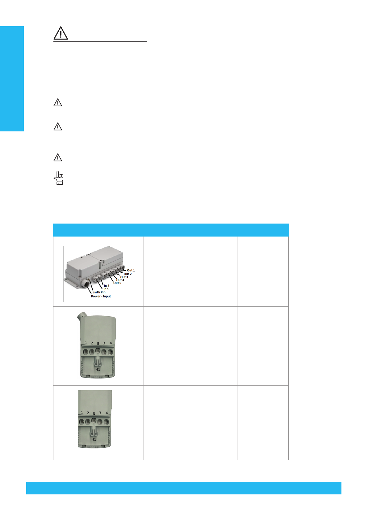
5.6 WIRING CONFIGURATION DIAGRAMS
Technical Data
5.6.2 C16 system
5.6.1 CU20 system
FUNCTION
SE4325 SE4400 STD SIZE SE4400 LARGE SIZE
ITEM DESCRIPTION ITEM DESCRIPTION ITEM DESCRIPTION
Power CP2001000A01069 Control Power
Unit
CP2001000A01069 Control Power Unit HB8X135-00 Handset
IN 1 HB8X135-00 Handset HB8X135-00 Handset 0821008 Port Plug
IN 2 0821008 Port Plug 0821008 Port Plug BL131HA11300A or
BL14HA11400A HILO Column
OUT 1/CH 1 BL131HA11300A
or BL14HA11400A HILO Column BL131HA11300A or
BL14HA11400A HILO Column BL131HA11300A or
BL14HA11400A HILO Column
OUT 2 /CH 2 31110H+101504K Backrest Actuator
– 150mm stroke
31110H+101504K Backrest Actuator
– 150mm stroke
31110H+101504K Backrest Actuator
– 150mm stroke
OUT 3/CH3 31110H+301004K Leg Rest Actuator
– 100mm spline
31110H+301004K Leg Rest Actuator –
100mm spline
31110H+301004K Leg Rest Actuator
– 100mm spline
OUT 4/CH 4 31120H+10050
04K(LAUS112092)
Seat Tilt Actuator
– 50mm stroke
31120H+1005004K
(LAUS112092)
Seat Tilt Actuator –
50mm stroke
31120H+1005004K
(LAUS112092
Seat Tilt Actuator
– 50mm stroke
OUT 5/CH 5 N/A N/A N/A N/A
18 © 2019Careleda M-03 WI-204rev 6 Edited 29.10.2019

5.6 WIRING CONFIGURATION DIAGRAMS
DO NOT USE CHAIR UNTIL YOU HAVE FULLY READ THE INSTRUCTIONS
5.7 RESET / INITIALISATION PROCEDURE FOR CU20 SYSTEM
Use the handset to perform the following procedures:
5.7.1 RESET
Suits both Phase 2, 3 & 4 Software – Reset the system by simultaneously pressing the Row 2 UP / DOWN (Backrest
Row) keys until the system stops beeping (approx. 5 seconds). Please note that the two keys must be activated at
exactly the same time.
5.7.2 INITIALISE
a. Phase 2 Software SW70133(MAU0204)/ SW70137(MAU0214 – Initialise the system by running the actuators to
their end-stop position as per below (press and hold the button until the actuator has stopped):
SE4325 STD – 160kg SE4400 STD – 160kg SE4400 Large Size – 300kg
a. Drive CH1 in a. Drive CH1 in a. Drive CH1 & CH2 in
b. Drive CH2 in b. Drive CH2 in b. Drive CH3 in
c. Drive CH3 in c. Drive CH3 in c. Drive CH4 in
d. Drive CH4 in d. Drive CH4 in d. Drive CH5 in
b. Phase 3 & 4 Software SW71071(MAU0349)/SW71022(MAU0330) – Initialise the system by pressing and holding
simultaneously Row 1 UP / DOWN (Hi-Lo Row) buttons until all functions have ceased to operate and the
buzzer sounds with 2 beeps (100ms ON, 100ms OFF)
5.8 MAXIMUM HEIGHT RESET AND STORE FUNCTION – for PHASE 3 & 4 SOFTWARE ONLY
SW71071(MAU0349)/SW71022(MAU0330)
5.8.1 STORE/SET MAXIMUM HEIGHT
This function allows the reprogramming of the maximum height of the HI-LO function of the chair system. It allows
for limitation, by supervisors, of the maximum height they wish the chair to function at for their circumstances i.e.
50mm, 100mm … innite up to the absolute maximum height of the system (default) - determined by the model of
BL14 column tted to your chair – i.e. 300mm or 400mm.
Using the handset, press and hold simultaneously for 5 seconds the Leg Rest UP Button (3rd row, Left button) & Seat
Tilt DOWN Button (4th Row, Right button) until Buzzer beeps once – refer to the Purple Rings on the diagrams in
Section 5.9
5.8.2 RESET MAXIMUM HEIGHT, to the default absolute maximum height
The absolute maximum height of the system - determined by the model of BL14 column tted to your chair – i.e.
300mm or 400mm.
Using the handset, press and hold simultaneously for 5 seconds the Leg Rest DOWN Button (3rd row, Right button)
& Seat Tilt UP Button (4th Row, Left button) until Buzzer beeps once – refer to the Green Rings on the diagrams in
Section 5.9
Technical Data
19© 2019 Careleda M-03 WI-204rev 6 Edited 29.10.2019
DO NOT USE CHAIR UNTIL YOU HAVE FULLY READ THE INSTRUCTIONS
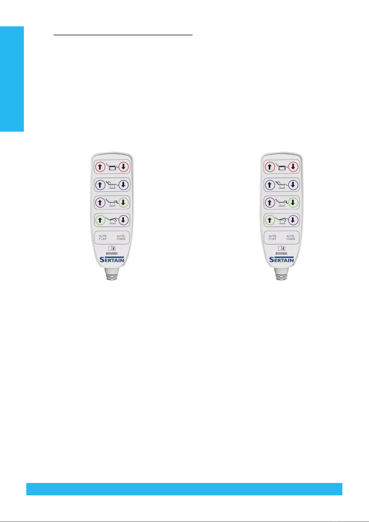
5.9 HANDSET FUNCTIONS / CHANNEL DIAGRAM
5.9.1 Blue rings indicate buttons to press and hold simultaneously for Reset procedure
5.9.2 Red rings indicate buttons to press and hold simultaneously for Initialisation procedure (Phase 3 & 4 software
only)
5.9.3 Green rings indicate buttons to press and hold simultaneously for RESET MAXIMUM Height (refer to Section
5.8.2)
5.9.4 Purple rings indicate buttons to press and hold simultaneously for STORE/SET MAXIMUM HEIGHT (refer to
Section 5.8.1)
SE4400 Standard Size SE4400 Large Size
HI-LO
Back Rest
Leg Rest
Seat
CH 1 OUT
CH 2 OUT
CH 3 OUT
CH 4 OUT
Bed Position Bed PositionChair Position Chair Position
CH 1 & CH 2 OUT
CH 3 OUT
CH 4 OUT
CH 5 OUT
CH 1 IN
CH 2 IN
CH 3 IN
CH 4 IN
CH 1 & CH 2 IN
CH 3 IN
CH 4 IN
CH 5 IN
HI-LO
Back Rest
Leg Rest
Seat
Technical Data
20 © 2019Careleda M-03 WI-204rev 6 Edited 29.10.2019
This manual suits for next models
1
Table of contents


