manuals.online logo
Brands
  1. Home
  2. •
  3. Brands
  4. •
  5. Johnson Controls
  6. •
  7. Camera Accessories
  8. •
  9. Johnson Controls Illusta PRO IBWT-P-ISWB-A User manual

Johnson Controls Illusta PRO IBWT-P-ISWB-A User manual

Using the tilt mount to attach the camera to a wall surface
(continued)
Figure 4
9. Insert the camera safety wire (2) (Figure 5) onto the ‘hook’ (1) (Figure 5) on
the flat bracket.
Security
Quick Start Guide
(A16381L36M_A)
Illustra Pro Gen4 12MP Fisheye camera Tilt Mount Accessory
(P/N IBWT-P-ISWB-A)
In the box
•1 x Tilt Mount
•1 x Adaptor plate
•4 x PlasticAnchors
•4 x TP4 Tapping Screws
•2 x Rubber inserts
•1 x Quick Start Guide
•1 x Guide Pattern
•7 x M3 Screws (4 for use with the Flat bracket and 3 for use with the
Adaptor plate)
Installation tools
•1 x Screwdriver
•1 x Drill
•1 x Wire cutters
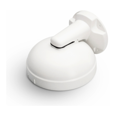
Figure 1: Pro Gen4 12MP Fisheye tilt mount accessory
Figure 1
Using the tilt mount to attach the camera to a wall surface
1. Place the mounting template sticker onto the wall surface.
2. On the wall surface drill four holes as per the information on the template
sticker and insert the four plastic screw anchors into the four holes.
3. Hold the tilt mount accessory up to the wall surface and align the four holes
on the tilt mount accessory with the four holes on the wall surface.
4. Insert the four TP4 Tapping screws (2) (Figure 2) into the four screw anchors
and use the screwdriver to securely attach the tilt mount accessory (1)
(Figure 2) to the wall surface.
Figure 2
5. Hold the adaptor plate (3) (Figure 3) up to the tilt mount (1) (Figure 3) and
align the three holes on the adaptor plate with the three holes on the tilt
mount.
6. Insert the three M3 screws (2) (Figure 3) into the three holes and use a
screwdriver to securely attach the adaptor plate (3) (Figure 3) to the tilt mount
(1) (Figure 3).
Using the tilt mount to attach the camera to a wall surface
(continued)
Figure 3
7. Hold the flat bracket (2) (Figure 4) that comes in the box with the camera up
to the tilt mount accessory (1) (Figure 4) and align the four holes on the flat
bracket with the four holes labelled ‘T’ on the tilt mount.
Note: If you are using a legacy Fisheye camera, then you do not need to
use the flat bracket. Use either the ‘M3’ or ‘M4’ holes on the flat bracket
when attaching a legacy Fisheye camera to the tilt mount.
8. Insert the four M3 screws (3) (Figure 4) into the four holes and use a
screwdriver to securely attach the flat bracket to the tilt mount.
Using the tilt mount to attach the camera to a wall surface
(continued)
Figure 5
Note: The pre-fitted ethernet cable that comes with the cameras can be
removed if the installation requires the use of an existing network cable, or, if
additional cables are required. You must use the supplied rubber grommet
with the cable to maintain the IP rating.
10. Use the screwdriver to remove the three screws on the camera rear cap cover
(1) (Figure 6).
11. Connect the pre-fitted Ethernet cable (or the existing network cable through
the rubber grommet) to a PoE compatible network device that supplies power
through the Ethernet cable.
OR
Route the 24Vac cable through the rubber grommet and connect the 24V AC
cable to the 2-pin port on the camera.
OR
Route audio and alarm cable through the rubber grommet and connect the
audio and alarm cables to the 8-pin terminal on the camera.
Security
Using the tilt mount to attach the camera to a wall surface
(continued)
12. Hold the rear cap (1) (Figure 6) up to the camera and align the three holes
on the rear cap with the three holes on the camera.
13. Insert the three screws into the three holes and use a screwdriver to
securely attach the rear cap cover to the camera.
14. OPTIONAL: Inserting a micro-SD card.
a. Use the screwdriver to remove the two screws on the SD card slot
cover (2) (Figure 6) and then insert a micro-SD card.
b. Hold the SD card slot cover back up to the camera and align the two
holes on the cover with the two holes on the camera.
c. Insert the two screws into the two holes and use a screwdriver to
securely attach the SD card cover to the camera.
Figure 6
Using the tilt mount to attach the camera to a wall surface
(continued)
15. Use a screwdriver to remove the safety wire screw (3) (Figure 7) on the
camera.
16. Insert the safety wire screw into the ‘loop’ at the end of the safety wire (2)
(Figure 7) and then insert the screw back into the hole on the camera.
17. Use a screwdriver to securely attach the screw into the camera.
Figure 7
18. Hold the camera up to the tilt mount and align the security screw (1) (Figure
8) with the tilt mount alignment mark (2) (Figure 8).
19. Hold the camera up to the flat bracket and insert the three screws on the
camera (1) (Figure 7) up into the three holes in the flat bracket and then
rotate the camera clockwise until it clicks into place on the flat bracket.
Note: Rotate the camera counterclockwise to remove it from the flat bracket.
Using the tilt mount to attach the camera to a wall surface
(continued)
Figure 8
20. Use the torx wrench to rotate the security screw (1) (Figure 9)
counterclockwise to securely attach the camera to the flat bracket.
Using the tilt mount to attach the camera to a wall surface
(continued)
Figure 9
© 2022 Johnson Controls. All rights reserved. JOHNSON CONTROLS, TYCO and
ILLUSTRA are trademarks and/or registered trademarks. Unauthorized use is strictly
prohibited.

Other Johnson Controls Camera Accessories manuals

Johnson Controls SL9 8BR User manual

Johnson Controls

Johnson Controls SL9 8BR User manual

Johnson Controls IBPN-M-IS12-0 User manual

Johnson Controls

Johnson Controls IBPN-M-IS12-0 User manual

Popular Camera Accessories manuals by other brands

Sony SAL-24105 Service manual

Sony

Sony SAL-24105 Service manual

Elite Screens Light-On CLR 3 Series user guide

Elite Screens

Elite Screens Light-On CLR 3 Series user guide

Wirthco battery doctor 20090 user manual

Wirthco

Wirthco battery doctor 20090 user manual

ION FCS Board Mount quick start guide

ION

ION FCS Board Mount quick start guide

Filmcity FC-A7G34 instruction manual

Filmcity

Filmcity FC-A7G34 instruction manual

Nauticam CR2470-Z instruction manual

Nauticam

Nauticam CR2470-Z instruction manual

Crestron CPC-CAMI Operation guide

Crestron

Crestron CPC-CAMI Operation guide

Brusa EVB1-400-40-HP Technical Data and Start-Up

Brusa

Brusa EVB1-400-40-HP Technical Data and Start-Up

Moog Videolarm AD8C-9 Specifications

Moog Videolarm

Moog Videolarm AD8C-9 Specifications

Sabre Switch TRIGGERSMART instruction manual

Sabre Switch

Sabre Switch TRIGGERSMART instruction manual

Voltacon Li-2021 48100R user manual

Voltacon

Voltacon Li-2021 48100R user manual

Geekoto C1 operation instruction

Geekoto

Geekoto C1 operation instruction

Husqvarna BLi22 Operator's manual

Husqvarna

Husqvarna BLi22 Operator's manual

Loreo 9005A operating instructions

Loreo

Loreo 9005A operating instructions

Moog Videolarm OH206T Product instructions

Moog Videolarm

Moog Videolarm OH206T Product instructions

Studio Titan STA-01-398 manual

Studio Titan

Studio Titan STA-01-398 manual

Kobalt KB 245-06 manual

Kobalt

Kobalt KB 245-06 manual

JVC CamiFlex FG-CAM-F4/U user manual

JVC

JVC CamiFlex FG-CAM-F4/U user manual

manuals.online logo
manuals.online logoBrands
  • About & Mission
  • Contact us
  • Privacy Policy
  • Terms and Conditions

Copyright 2025 Manuals.Online. All Rights Reserved.