SET SOLAR Volta SETM60 User manual

1
SET SOLAR
INSTALLATION
MANUEL

2
CONTENTS
1. SAFETY PRECAUTIONS ..................................................................................................................... 3
1.1. GENERAL WARNING..................................................................................................................... 3
1.2. INSTALLATION SAFETY
1.3. FIRE SAFETY.................................................................................................................................. 5
2. LIMITATION OF LIABILITY................................................................................................................. 5
3. GENERAL INFORMATION................................................................................................................. 5
4. MECHANICAL INSTALLATION........................................................................................................... 7
4.1. SITE SELECTION............................................................................................................................. 7
4.2. TILT ANGLE ................................................................................................................................... 7
4.3. MOUNTING................................................................................................................................... 8
4.3.1. Mounting Using Frame Bolts Holes....................................................................................... 8
4.3.2. Mounting with Clamps .......................................................................................................... 9
4.3.2.1. Clamp Mounting on Long Sides ofthe Frames............................................................... 9
5. WIRING...........................................................................................................................................10
6. GROUNDING...................................................................................................................................11
7. MAINTENANCE AND REPAIR ..........................................................................................................12

3
1.
SAFETY PRECAUTIONS
Professional installer must read these guidelines carefully and strictly follow these
instructions. Failure to follow these instructions may result in death, injury or property
damage. The installation and handling of PV modules require professional skills and should
only be performed by qualified professionals. Please retain this manual for future reference.
1.1. GENERAL WARNING
•All modules must be installed by licensed electricians.
•Electricians must take precautions about occupational health and safety.
•All Set Solar PV module have junction box, wires and connectors so PV module donot need
any extra wires.
•Do not use any mirror or glass etc. for focusing sunlight to the PVmodule
•PV module are used for converting sunlight to DC electrical energy so they must be set up
outside .
•Do not paint the panel surface or back sheet.
•Do not paste or attach anything to the panel’s backsheet.
•Do not remove anything from the PV module. PV module must be disassembled by
professionals.

4
1.2. INSTALLATION SAFETY
•Insulated gloves must be worn when carrying
the PV module.
•Insulated tools should be used for electrical
connections.
•Inappropriate transportation or installation can
cause the panel to become damaged.
•Please do not lift PV module from junction box
or wires.
•Please do not put excessive pressure on PV
panels.
•Do not put any foreign object on the PV module.
•Do not drop PV module or do not throw
anything towards PV panel.
•Backsheet of the PV module should avoid direct
contact the sun.
•Do not wear any metal accessories during operation.
•Do not assembly the PV module under the rainy or windyconditions.
•Safety procedures must be followed for all parts of the PV module installation process.
•Do not install the PV module near open flame or flammablematerials.
•Insulated gloves must be worn when installing the PV modules.
•Please do not drill into the frame.
•Under normal conditions, a photovoltaic module is likely to experience conditions that
produce more current and/or voltage than reported at standard test conditions (STC).
Accordingly, the values of Isc and Voc marked on this module should be multiplied by a
factor of 1.25 when determining component voltage ratings, conductor capacities fuse
sizes, and size of controls connected to the PV output.
•Matte color plates can be used during installation for avoiding any currentincrease.
•PV module must be grounded properly. Recommended connectors and grounding wire
must be used. Grounding wire must be fixed to the PV module properly.

5
1.3. FIRE SAFETY
•Related regulations must be followed for stable structural
integrity.
•Do not setup PV module on the unsuitableroofs.
•Do not assembly the PV module next to the flammable material
and flammable facilities.
•Please refer to local laws and regulations before installing
modules and abide by requirements on building fire protection. According to the
corresponding certification standards, the fire rating of Set Solar modules is Class C.
2.
LIMITATION OF LIABILITY
Set Solar is not responsible for any kind of damage, including but not limited to module
operation and system installation error, and personnel injury, hurt, and property loss caused
by failure to following the instructions in this Manual.
3.
GENERAL INFORMATION
Module Type
Volta
SETM60
Volta
SETM72
Volta +
SETM120
Volta +
SETM144
Class of protection against electrical
Shock
Class II
Maximum system Voltage (Vsys)
1500
Voltage at open-circuit (Voc)
40.93
49.29
41.12
49.47
Current at short-circuit (Isc) (A)
10.26
10.19
11.59
11.60
PV module maximum power (Pmax)
335
400
375
455
Maximum overcurrent production rating
(A)
15
15
20
20
Power, current and voltage tolerance
± 3%
Temperature coefficient for voltage at
open-circuit
Beta [%/°C]
-0.282
-0.254
Temperature coefficient for maximum
power
Gama [%/°C]
-0.376
-0.318
Temperature coefficient for short-circuit
current
Alpha [%/°C]
0.043
0.054

6
•Set Solar PV modules operate at temperatures between -40°C and +85°C .
•Module electrical ratings are measured under Standard Test Conditions (STC) of 1000 W/m2
irradiance, with an AM1.5 spectrum, and a cell temperature of 25°C. The module might
produce more or less voltage or current than rated value in uncertainty condition.
•Every module has its own wire (cross-sectional area 4 mm²) and MC4-Evo2 connectors.
Also, every module has three Schottky bypass diodes.(Type: GP3045 for Volta series;
Maximum Peak reverse voltage: 45V, forward current: 15A ;For Volt+ series Type:TM3045-
20; Maximum Peak reverse voltage: 45V, forward current: 20A and maximum function
temperature ranges: -55°C / 200°C)When choosing the proper conductive material, these
information must be taken into the consideration, also it must be corresponded to TS EN
61730-1. Mechanic load: Snow and wind load Test load (snow) 5400Pa, Test load (wind)
2400Pa, safety factor 1.5, Design load (snow) 3600Pa, Design Load (wind)1600Pa.
•All Set Solar PV modules have three labels.
•Nameplate: It is found on the back of the PV module. Specific information from datasheets
exist in there .
•Barcode plates: There are two barcode plates on the module. First one is found inside the
top right corner of the glass. Second one is found on the frame. They contain product
barcode.
Volta Series Barcode
Volta+ Series Barcode
Label

7
4.
MECHANICAL INSTALLATION
Starting from this line, all the given instructions are recommendations. All design, installation
and calculations must be done by licensed people.
4.1. SITE SELECTION
In most applications, Set Solar PV modules should be installed in a location where they will
receive maximum sunlight throughout the year. Even minor partial shading reduces yields. A
module can be considered to be unshaded if its entire surface is free from shading all year
round. Sunlight should be able to reach the module even on the shortest day of the year.
Constant shading conditions can affect module service lifetime, due to accelerated ageing of
the encapsulation material and thermal stress on the bypass diodes.
The module's limit working ambient temperature range is from -40℃to 85℃. Maximum
altitude less than or equal to 2000m. The maximum mechanical load is 5400 Pa on the front
and 2400 Pa on the back
4.2. TILT ANGLE
The tilt angle measurement of the PV module refers to measuring the angle between the
module and the horizontal ground surface. For different projects there are different mounting
angles. Set Solar recommends that the mounting tilt angle should not be less than 10°, or in
accordance with local regulations or follow the recommendations of experienced PV module
installers.
8
4.3. MOUNTING
4.3.1. Mounting Using Frame Bolts Holes
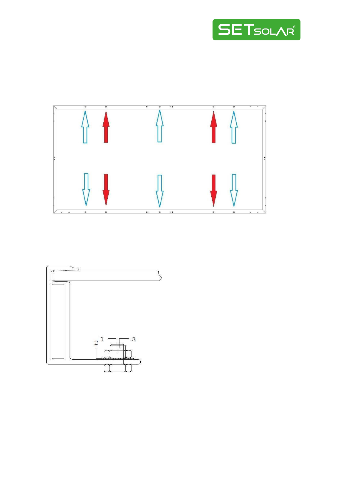
Each module must be securely fastened using a minimum of 4 mounting holes (9mm×14mm)
at locations shown below. For maximum security against strong winds and heavy snow falls,
all 10 mounting holes should be used to secure the module.
➢Red Arrows: holes for mounting the PV modules to the substructure
➢Blue Arrows: additional holes for maximum security
➢The additional units as follows diagram:
1. Stainless steel m6 nut
2. Stainless steel washer
3. Stainless steel M6 t-head bolt

9
4.3.2. Mounting with Clamps
The module clamps should not come into contact with the front glass and must not deform
the frame. Be sure to avoid shadowing effects from the module clamps. The module frame is
not to be modified under any circumstances. When choosing this type of clamp-mounting
method, please be sure to use at least four clamps on each module. Depending on the local
wind and snow loads, additional clamps or support would be required to ensure the module
can bear the load. The applied torque value should be big enough to fix the modules steadily.
Please find detailed mounting information in the below illustration, the mounting place
distance is suggested bigger than J and less than K. The min length of clamp is 50mm. The
position of the clamp should be between 1/5 and 1/4 of the long side of the module.
Clamp Frame
clamp Frame
4.3.2.1. Clamp Mounting on Long Sides of the Frames
Mounting Rail
Mounting Rail
Mounting bolt
M8 Bolt
Mounting Rail
Clamp
10
Module Type
Module Dimensions(AxB)
J (mm)
K (mm)
SETM60
1665x1002
330
420
SETM72
1979x1002
400
495
SETM120
1755x1038
350
440
SETM144
2094x1038
420
520
5.
WIRING
Modules are supplied with cables and connectors to be used for system electrical connections.
It is not recommended to use modules with different configurations and electrical
characteristics in the same system.
To ensure proper system operation the correct cable connection polarity should be observed
when connecting the modules to each other or to a load, such as inverter, a battery etc. If
modules were not connected correctly, the bypass diode could be destroyed.
Every module has its own wire (cross-sectional area 4 mm²) and MC4 -EVO 2 connectors. Also,
every module has three Schottky bypass diodes (Type: TM3045-20; Max. peak reverse voltage:
45V, forward current: 20 A, Max function temperature range: -55°C /200°C). When choosing
the proper conductive material, these information must be taken into the consideration, also
it must be corresponded to TS EN 61730-1.
Modules can be connected in series to obtain a high operating voltage. The system voltage is
equal to the sum of the voltage of each module. Modules can also be connected in parallel to
obtain a high operating current. The system current is equal to the sum of the current of each
string of modules.
Each module has two standards 90°C sunlight resistant output cables each terminated with
plug & play connectors. The PV Wire cables are 12AWG in size. This cable is suitable for
applications where wiring is exposed to the direct sunlight. We require that all wiring and
electrical connections comply with the appropriate National Electrical Code.
For field connections, use at least 4mm2 copper wires insulated for a minimum of 90°C and
sunlight resistance with insulation designated as PV Wire.
Under normal conditions, a module is likely to experience conditions that produce more
current and/or voltage than reported at standard test conditions. The suggested fuse must be
used for overcurrent protection. Accordingly, the values of Isc and Voc marked on this module
should be multiplied by a factor of 1.25 when determining component voltage ratings,
conductor ampacities, fuse sizes, and size of controls connected to the PVoutput.

11
The maximum number of series connected modules depends on system design, the type of
inverter used and environmental conditions. It should be noted that modules must not be
connected together to create a voltage higher than the permitted system voltage. There is no
limitation on the number of modules that can be connected in parallel; the number of modules
is determined by system design parameters such as current or poweroutput.
6.
GROUNDING
•All module frames and mounting racks must be properly grounded in accordance with
appropriate respective National Electrical Code.
•Proper grounding is achieved by bonding the module frame(s) and all metallic structural
members together continuously using a suitable grounding conductor. The grounding
conductor or strap may be copper, copper alloy, or any other material acceptable for use
as an electrical conductor per respective National Electrical Codes. The grounding
conductor must then make a connection to earth using a suitable earth ground electrode.

12
7.
MAINTENANCE AND REPAIR
•A buildup of dust or dirt on the module(s) front face will result in a decreased energy
output. Clean the panel(s) preferably once per year if possible (depend on site conditions)
using a soft cloth dry or damp, as necessary. Water with high mineral content may leave
deposits on the glass surface and is not recommended.
•In order to reduce the potential for electrical and thermal shock injuries, recommending
that cleaning PV modules during early morning or late afternoon hours when solar
radiation is low and themodules are cooler, especially in regions withhotter temperatures
•Never attempt to clean a PV module with broken glass or other signs of exposed wiring, as
this presents a shock hazard.
•Never use chemicals when cleaning modules as this may affect the module warranty and
energy output.
•To protect against electric shock or injury, electrical or mechanical inspections and
maintenance should be performed by qualified personnelonly.
This manual suits for next models
3
Table of contents
Popular Solar Panel manuals by other brands


Sonnenstrom Fabrik
Sonnenstrom Fabrik Excellent installation guide

Baintech
Baintech BTBLANKET300 user guide

Viessmann
Viessmann Vitosol 300-T installation instructions

atersa
atersa A-70M Installation and user manual

Vaillant
Vaillant VPV P 300/3 M SWF Operating, installation and maintenance instructions

DAH Solar
DAH Solar DHM-72X10/FS user manual


