SET COMPACTRIO RDK9316 User manual

SET9010MAN0100 USER MANUAL
Issue: 01 RDK9316
Page 1 of 42
Copyrights:
SET GmbH
All rights reserved.
Information contained herein is the propert of SET GmbH and shall not be duplicated,
copied, used or disclosed in whole or in part of an purpose. The right of duplication, use or
disclosure is permitted onl b written agreement of SET GmbH, August Braun Str. 1, 88239
Wangen/German .
LabVIEW, CompactRIO, TestStand are Trademarks of National Instruments
U S E R M A N U A L
CMPACTRI
RES LVER T DIGITAL CNVERSI N MDULE
RDK9316
Art.Nr. 86257
SET GmbH
August-Braun-Str. 1
88239 Wangen/Allgäu
German
Tel.: +49 (0)7522 91687-600
Fax: +49 (0)7522 91687-899

SET9010MAN0100 USER MANUAL
Issue: 01 RDK9316
Page 2 of 42
Table f Contents
1. Important Instructions ....................................................................................................................... 4
1.1 Initial Inspection ................................................................................................................................. 4
1.2 Safety Instructions .............................................................................................................................. 4
1.2.1 Module Failure ................................................................................................................................... 4
1.2.2 Impermissible Applications ................................................................................................................ 4
1.2.3 Module Installation And Removal ...................................................................................................... 4
1.2.4 Electrical Connections ........................................................................................................................ 4
2. Module verview ............................................................................................................................... 5
3. Getting Started ................................................................................................................................... 6
3.1 Software-Requirements ..................................................................................................................... 6
3.2 Driver-Installation .............................................................................................................................. 6
3.3 RDK9316 Compact RI LabVIEW Drivers ............................................................................................ 7
3.3.1 Copying The Driver Files Into New Projects ...................................................................................... 11
3.3.2 NI PCI/PXI FPGA-Card Driver Application .......................................................................................... 13
3.3.2.1 Creation of a new Project ................................................................................................................. 13
3.3.2.2 Creating a New FPGA-Target ............................................................................................................ 14
3.3.2.3 Adding An R-Series Expansion Chassis .............................................................................................. 16
3.3.2.4 Adding The RDK9316 Driver Components To A Project ..................................................................... 17
3.3.2.5 Adding RDK9316 Modules To The Project Via Drag-And-Drop Function ........................................... 18
3.3.2.6 Adding RDK9316 Modules To The Project Via The Discovery-Function ............................................. 19
3.3.2.7 Adding FPGA Example-Applications .................................................................................................. 23
3.3.2.8 Saving The Project ............................................................................................................................ 24
3.3.2.9 Compiling And Running The Example Application ............................................................................ 25
3.3.3 Using The Driver Together With A NI RealTime CompactRI ............................................................ 26
3.4 Connecting The Resolver .................................................................................................................. 27
3.5 Running The Application Example .................................................................................................... 27
4. Application Development ................................................................................................................. 28
4.1.1 RDK9316 Driver And Communication ............................................................................................... 28
4.1.1.1 Driver-VI Implementation ................................................................................................................. 28
4.1.1.2 Triggering RDK9316 Functions Via Functions-VIs ............................................................................. 29
4.1.1.3 Initialising And Clearing The FIF Buffers ......................................................................................... 29
4.1.1.4 Application To Module Communication Diagram ............................................................................. 31
4.2 RDK9316 Driver-Instructions ............................................................................................................ 33
4.3 RDK9316 Driver Error Codes ............................................................................................................. 37

SET9010MAN0100 USER MANUAL
Issue: 01 RDK9316
Page 3 of 42
4.4 Module Identification Under LabVIEW ............................................................................................. 39
4.5 Saving The Setup .............................................................................................................................. 39
4.6 Auto Ratio ........................................................................................................................................ 39
5. Technical Specification ..................................................................................................................... 40
5.1 Housing ............................................................................................................................................ 40
5.2 External Power Supply ...................................................................................................................... 40
5.3 Excitation utput ............................................................................................................................. 40
5.4 Sinus And Cosine Signal Inputs ......................................................................................................... 41
5.5 Position Processing ........................................................................................................................... 41
5.6 Environmental Conditions ................................................................................................................ 41
5.7 Connector Pinout.............................................................................................................................. 42
6. Module Calibration ........................................................................................................................... 42
7. Module Maintenance ....................................................................................................................... 42
8. Service Address ................................................................................................................................ 42

SET9010MAN0100
U
Issue: 01
RDK9316
1. IMP RTANT I
NSTRUCTI NS
Please read all
instructions carefull before the RDK931
connected to other equipment!
1.1 INITIAL INSPECTI N
Check that the shipment is complete and note whether an damage has occurred d
transport. If the contents
are
immediatel , and notif the SET GmbH service contact to facilitate the repair or replacement
of the module. The address is listed in the back of the manual.
The following parts should be included in the shipme
RDK9316
module
CD-
ROM with driver software,
1.2 SAFETY I
NSTRUCTI NS
1.2.1 MDULE FAILURE
Do not install
obviousl damaged:
•
ph sical damage
•
lose parts inside the module
1.2.2 IMPERMISSIBLE A
PPLICATI NS
The module is designed for laborator use. Installing or operating the
module in explosive or hazardous environments is not permissible and ma
result in
serious injur or death!
1.2.3 MDULE I
NSTALLATI N
Hot Surface!
The
module ma be hot. Touching the module ma result in bod injur
1.2.4 ELECTRICAL C
NNECTI NS
The module is not designed to isolate voltage levels of more than 50V
Do not exceed the voltage levels according to the technical specifications.
Not following
injur or death!
U
SER MANUAL
RDK9316
Page 4 of 42
NSTRUCTI NS
instructions carefull before the RDK931
6
is installed into a cRIO chassis or
connected to other equipment!
Check that the shipment is complete and note whether an damage has occurred d
are
incomplete or
there is damage, file a claim with the carrier
immediatel , and notif the SET GmbH service contact to facilitate the repair or replacement
of the module. The address is listed in the back of the manual.
The following parts should be included in the shipme
nt:
module
ROM with driver software,
application examples
and manual
NSTRUCTI NS
the RDK9316
module into a cRIO chassis when the module is
obviousl damaged:
ph sical damage
lose parts inside the module
PPLICATI NS
The module is designed for laborator use. Installing or operating the
module in explosive or hazardous environments is not permissible and ma
serious injur or death!
NSTALLATI N
AND REM VAL
module ma be hot. Touching the module ma result in bod injur
NNECTI NS
The module is not designed to isolate voltage levels of more than 50V
Do not exceed the voltage levels according to the technical specifications.
Not following
this instruction ma result in module damage and serious
injur or death!
is installed into a cRIO chassis or
Check that the shipment is complete and note whether an damage has occurred d
uring
there is damage, file a claim with the carrier
immediatel , and notif the SET GmbH service contact to facilitate the repair or replacement
and manual
module into a cRIO chassis when the module is
The module is designed for laborator use. Installing or operating the
module in explosive or hazardous environments is not permissible and ma
module ma be hot. Touching the module ma result in bod injur
!
The module is not designed to isolate voltage levels of more than 50V
DC.
Do not exceed the voltage levels according to the technical specifications.
this instruction ma result in module damage and serious

SET9010MAN0100 USER MANUAL
Issue: 01 RDK9316
Page 5 of 42
2. MDULE VERVIEW
RDK 9316 is a compact, reliable and highl versatile Resolver-to-digital conversion module.
All commonl used Resolvers can be easil connected to the module without an additional
signal adaption. The module has a built-in excitation oscillator inclusive power stage which
can drive most Resolvers directl without the necessit of an external power booster. All
module parameter are interactivel adjustable via software. A sensor-detection functionalit
automaticall adjusts the module to the specific sensor ratio.
freq.
demod.
Controll
Sensor
RDK 9316
The RDK 9316 accepts a wide voltage suppl range from 9V to 36V and provides galvanic
isolation between the cRIO rack and the demodulator interface. The module is operable
within the NI cRIO real time environment and can also be plugged into a NI R-series
expansion chassis with PCI / PXI FPGA card. Included in deliver are all drivers required for
the cRIO s stems and LabVIEW integration examples.
9-36V
Reg
Excitation
Demodulator
SIN HI
SIN LO
COS HI
COS LO
EXEC HI
EXEC LO
VS P
COM
+
-
Resolver
Engine
RDK9316 applications include industrial and militar position control s stems such as motor
control, robotics and man kinds of servo loops which use Resolvers.

SET9010MAN0100 USER MANUAL
Issue: 01 RDK9316
Page 6 of 42
3. GETTING STARTED
3.1 SFTWARE-REQUIREMENTS
To use the RDK FPGA-Driver the following NI Software Components must be installed first:
•LabVIEW
•LabVIEW FPGA Module
•SET RDK-9316 C-Series Module („Setup.exe“ included on the SET RDK Driver-CD)
3.2 DRIVER-INSTALLATI N
After Installation of the NI Software Components, the RDK driver software itself must be
installed. To do this use the RDK9316 CD-ROM and follow the following instructions.
To start the installation process, execute the „setup.exe” program on the CD-ROM.
Please follow the instructions of the setup program to complete the driver installation.
When the installation is completed successfull , the host s stem is read to use RDK9316
modules in a LabVIEW project.

SET9010MAN0100 USER MANUAL
Issue: 01 RDK9316
Page 7 of 42
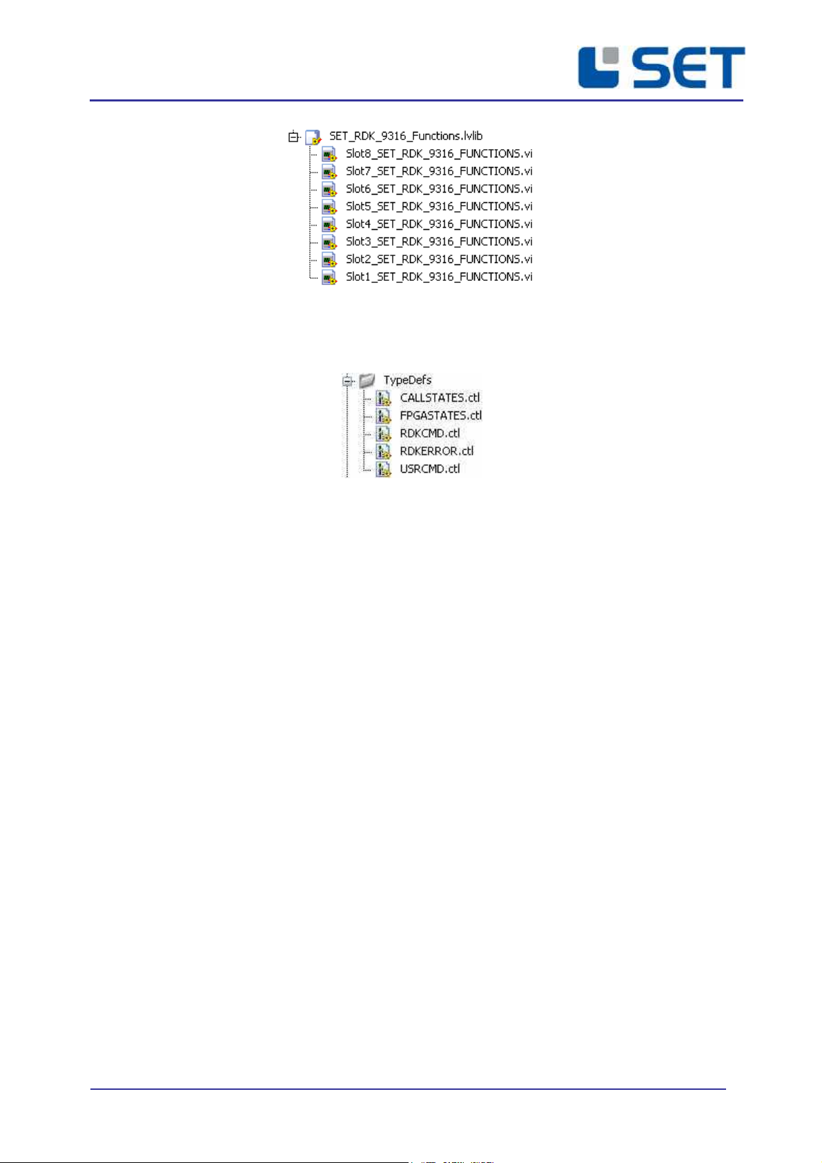
3.3 RDK9316 CMPACT RI LABVIEW DRIVERS
The driver application is demonstrated within a LabVIEW example project. To cop the driver
components into a new project, use the drag & drop function.
LabVIEW driver components
The LabVIEW FPGA software driver for the RDK9316 module comprises eight driver VI’s
which control the serial data transfer between the modules and the FPGA via SPI interfaces.
(Refer to the VI-librar „SET_RDK_9316_Drivers.lvlib“).
Each module slot applies to its own driver-VI
Each driver VI uses 2 FIFO buffers to communicate with the LabVIEW application. The FIFO
buffers are organized in CommandIN-FIFOs and CommandOUT-FIFOs for bidirectional data
flow from the application to the module and versus vice. Note that these buffers are pre-
defined in terms of name and size and should not be modified to ensure correct operation.
Each driver-VI uses two command FIF s
The user interface is formed from eight slot specific „Functions-VIs“, which perform the
driver calls b use of the communication-FIFOs.
(Refer to the VI-librar „SET_RDK_9316_Functions.lvlib“).
SET9010MAN0100 USER MANUAL
Issue: 01 RDK9316
Page 8 of 42
Each slot applies a specific functions-VI
The folder „T peDefs“ gives data t pe definitions used within the drivers: error codes and
module commands.
LabVIEW driver data type definitions
•USRCMD.ctl
Defines the applicable RDK9316 commands
•RDKERROR.ctl
Defines the driver error codes
•RDKCMD.ctl
For driver internal use
•CALLSTATES.ctl
For driver internal use
•FPGASTATES.ctl
For driver internal use
The example project alread covers all module slots with the maximum number of modules,
which is four, when an R-Series Expansion Chassis is applied and up to eight modules for a
cRIO-Chassis. The names of the modules in the project and the correlating modules I/O
channels are pre-defined and should not be changed for correct operation.

SET9010MAN0100 USER MANUAL
Issue: 01 RDK9316
Page 9 of 42
The example project includes all module slots
The example project also defines all required data signals:
Example project data signal definitions
The example project modules can be copied to a new project. Alternativel , when the
automatic LabVIEW module detection mechanism “Discover C-Series Modules” is used,
attention on identifier assignment should be paid to avoid naming conflicts (refer to chapter
3.3.2.6).
Three example files are included to demonstrate the driver-VI application:
Tree example programmes for the R-Series Expansion Chassis and cRI -Chassis
•SET_RDK_9316_Example_Slot_1.vi

SET9010MAN0100 USER MANUAL
Issue: 01 RDK9316
Page 10 of 42
Program example which demonstrates the application of a single RDK9316 module
connected to slot 1 of a (PCI) FPGA R-Series Expansion-Chassis or a cRIO-Chassis.
•SET_RDK_9316_Example_Slot_1-4.vi
Program example which demonstrates the application of four RDK9316 modules
connected to a (PCI) FPGA R-Series Expansion-Chassis or a cRIO-Chassis.
•SET_RDK_9316_Example_Slot_1-8.vi
Program example which demonstrates the application of eight RDK9316 modules
connected to a cRIO-Chassis.

SET9010MAN0100 USER MANUAL
Issue: 01 RDK9316
Page 11 of 42
3.3.1 CPYING THE DRIVER FILES INT NEW PR JECTS
The example below provides all software components to get started with a new project. To
cop the files into the new project, simpl use the drag&drop function. The example project
demonstrates the driver operation on two different target platforms.
Example Project Structure
To integrate the LabVIEW diver into a new or an existing project, all files from the example
project must be copied into the new project folder. Make sure that the file and folder names
LabVIEW driver integration for
a NI PCI-FPGA-Card in
combination with a (4 Slot) R-
Series Expansion Chassis
LabVIEW driver integration for
a CompactRIO-Chassis with up
to 8 slots.

SET9010MAN0100 USER MANUAL
Issue: 01 RDK9316
Page 12 of 42
are not modified during the cop process as the correct function of the drivers will be
affected thereb .
All files must be copied into the new project folder

SET9010MAN0100 USER MANUAL
Issue: 01 RDK9316
Page 13 of 42
3.3.2 NI PCI/PXI FPGA-CARD DRIVER APPLICATI N
The example below demonstrates the driver integration for a NI PCI-FPGA card together with
an R-Series Expansion Chassis.
3.3.2.1 CREATI N F A NEW PR JECT
When all driver files are copied into the new project folder, the example project is opened
within the new project folder. To integrate the driver into an existing LabVIEW project, the
target project must be opened subsequentl . Alternativel , to start a new project „File
New Project“ must be clicked.
pening the target project or creating a new project

SET9010MAN0100 USER MANUAL
Issue: 01 RDK9316
Page 14 of 42
3.3.2.2 CREATING A NEW FPGA-TARGET
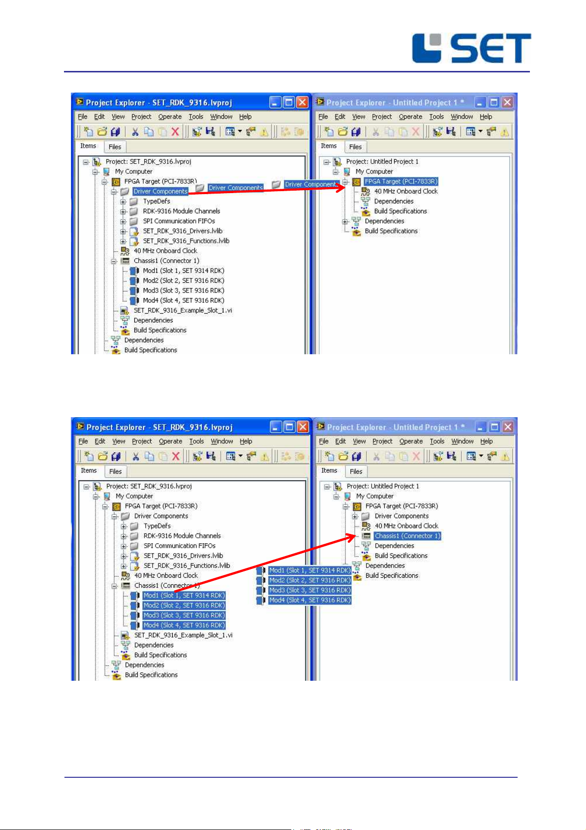
Both project windows can be aligned as shown below. The driver components can be copied
into a new project via drag-and-drop function Note that the STRG-ke must be pressed
during drag-and-drop to cop the element. Otherwise the element will be removed from the
example project. To prevent faults, the following module installation sequence must be
followed exactl .
The driver components can be copied by use of the drag-and-drop function

SET9010MAN0100 USER MANUAL
Issue: 01 RDK9316
Page 15 of 42
To add a new FPGA-Target use the mouse and click (right button) onto the computer s mbol
and select: „New Targets and Devices“.
Select an existing FPGA-Target or define a new device.

SET9010MAN0100 USER MANUAL
Issue: 01 RDK9316
Page 16 of 42
The new FGPA-Target is now added to the project-structure.
3.3.2.3 ADDING AN R-SERIES EXPANSI N CHASSIS
To use an RDK9316 module together with a FPGA chassis, an „R-Series Expansion Chassis“
must be appended to the actual project structure. Use the mouse and click with the right
button onto the newl added FPGA-Target and select „New R Series Expansion Chassis“.
Confirm the dialog with „OK“.

SET9010MAN0100 USER MANUAL
Issue: 01 RDK9316
Page 17 of 42
The newl added R-Series Expansion Chassis is now included in the project structure:
3.3.2.4 ADDING THE RDK9316 DRIVER CMP NENTS T A PR JECT
To adopt the driver components to the new project the files must be copied before the
RDK9316 modules are integrated.
SET9010MAN0100 USER MANUAL
Issue: 01 RDK9316
Page 18 of 42
3.3.2.5 ADDING RDK9316 MDULES T THE PR JECT VIA DRAG-AND-DR P FUNCTI N
As all driver components for all slots are alread defined within the example project the will
be copied with the drag-and-drop function. Components which are not used in the new
application should be removed from the new project.

SET9010MAN0100 USER MANUAL
Issue: 01 RDK9316
Page 19 of 42
Caution:
Do not erase the contents of the libraries “SET_RDK_9316_Drivers.lvlib“ and
“SET_RDK_9316_Functions.lvlib“.
3.3.2.6 ADDING RDK9316 MDULES T THE PR JECT VIA THE DISC VERY-FUNCTI N
The LabVIEW function “Discover C-Series Modules” automaticall detects and integrates
cRIO modules which are plugged into an R-Series Expansion Chassis or a cRIO-Chassis.
It is important that the I/O names of the Module match the names expected b the driver.
Normall the right I/O name is created b LabVIEW within the discover function. However
on some LabVIEW versions the I/O Names are different. In this case ou need to change the
names of the I/O’s to the names used in the example project, or cop the I/O from the
example project and delete the automaticall created ones.
(PCI/PXI) FPGA-Target With R-Series Expansion Chassis:
Install the new (PCI/PXI) FPGA target together with the R-Series Expansion chassis within the
new project (refer to 3.3.2.2). Activate the discover function when the following window
pops up:
This initiates LabVIEW to check the chassis for cRIO modules.

SET9010MAN0100 USER MANUAL
Issue: 01 RDK9316
Page 20 of 42
When the search procedure is complete, LabVIEW visualizes the detected cRIO modules
within the project structure as shown below. Additionall , for ever detected module a
virtual folder is automaticall installed.
Now, the virtual folder „Driver Components“ must be copied from the example project to
the new FPGA target within the LabVIEW project.
This manual suits for next models
1
Table of contents


