SEVADIS MaxiCharger AC wallbox User manual
Installation Manual
MaxiCharger AC Wallbox
ELECTRIC VEHICLE CHARGER

i
Trademarks
Autel®, MaxiSys®, MaxiDAS®, MaxiScan®, MaxiCheck®, and MaxiRecorder® are
trademarks of Autel Intelligent Technology Corp., Ltd., registered in China, the
United States and other countries. All other marks are trademarks or registered
trademarks of their respective holders.
Copyright Information
No part of this manual may be reproduced, stored in a retrieval system or
transmitted, in any form or by any means, electronic, mechanical, photocopying,
recording, or otherwise without the prior written permission of Autel.
Disclaimer of Warranties and Limitation of Liabilities
All information, specifications and illustrations in this manual are based on the
latest information available at the time of printing.
Autel reserves the right to make changes at any time without notice. While
information of this manual has been carefully checked for accuracy, no guarantee
is given for the completeness and correctness of the contents, including but not
limited to the product specifications, functions, and illustrations.
Autel will not be liable for any direct, special, incidental, indirect damages or any
economic consequential damages (including the loss of profits).
IMPORTANT
Before operating or maintaining this unit, please read this manual carefully, paying
extra attention to the safety warnings and precautions.
For Services and Support:
Web: www.sevadis.com
Tel: +44 (0)330 058 7144
Email: [email protected]
For technical assistance in all other markets, please contact your local selling
agent.
ii
Safety Information
For your own safety and the safety of others, and to prevent damage to the device
and vehicles upon which it is used, it is important that the safety instructions
presented throughout this manual be read and understood by all persons
operating or coming into contact with the device.
Safety Messages
Safety messages are provided to help prevent personal injury and equipment
damage. All safety messages are introduced by a single word indicating the
hazard level.
DANGER
Indicates an imminently hazardous situation which, if not avoided, will result in
death or serious injury to the operator or to bystanders.
WARNING
Indicates a potentially hazardous situation which, if not avoided, could result in
death or serious injury to the operator or to bystanders.
Safety Instructions
The safety messages herein cover situations Autel is aware of. Autel cannot know,
evaluate or advise you as to all of the possible hazards. You must be certain that
any condition or service procedure encountered does not jeopardize your personal
safety.
SAFETY WARNINGS
Read all the instructions before you use this device.
Do not install or use the device near flammable, explosive, harsh, or
combustible materials, chemicals, or vapors.
Turn off power at the circuit breaker before installing or cleaning the device.
This device should be supervised when used around children.

iii
This device must be grounded through a permanent wiring system or an
equipment-grounding conductor.
Use the device only within the specified operating parameters.
Do not use the device if it is defective, appears cracked, frayed, broken or
otherwise damaged, or fails to operate.
Do not use the device if the flexible power cord or EV cable is frayed, broken,
or otherwise damaged, or if it fails to operate.
Do not attempt to disassemble, repair, tamper with or modify the device.
Handle the device with care during transportation. Do not subject it to strong
force or impact, pull, twist, tangle, drag or step on the device, to prevent
damage to it and any of its components.
Do not insert fingers or foreign objects into any part of the device.
CAUTION
Do not use private power generators as a power source for charging.
Incorrect installation and testing of the device could potentially damage the
vehicle's battery, components, and/or the device itself.
Do not operate the device in temperatures outside its operating range.

iv
CONTENTS
SAFETY INFORMATION .................................................................................
II
SAFETY MESSAGES ......................................................................................
II
SAFETY INSTRUCTIONS ...............................................................................
II
USING THIS MANUAL ................................................................................... 1
CONVENTIONS ................................................................................................... 1
2 GENERAL INTRODUCTION .......................................................................... 3
2.1 PRODUCT OVERVIEW .................................................................................... 4
2.2 OPTIONS ..................................................................................................... 7
2.3 SPECIFICATIONS ........................................................................................... 9
3 INSTALLATION .............................................................................................. 11
3.1 PREPARE FOR INSTALLATION ......................................................................... 11
3.2 MECHANICAL INSTALLATION ......................................................................... 12
3.3 POWER SUPPLY WIRING ............................................................................. 19
4 TROUBLESHOOTING AND SERVICE ........................................................ 23
4.1 TROUBLESHOOTING TABLE .......................................................................... 23
4.2 SERVICE .................................................................................................... 26
5 COMPLIANCE INFORMATION .................................................................... 27
6 WARRANTY .................................................................................................. 28

1
Using This Manual
This manual contains device usage instructions.
Some illustrations shown in this manual may contain modules and optional
equipment that are not included in your system. Contact your sales representative
for availability of other modules and optional tools or accessories.
Conventions
The following conventions are used.
Bold Text
Bold text is used to highlight selectable items such as buttons and menu options.
Example:
Tap OK.
Notes and Important Messages
Notes
A NOTE provides helpful information such as additional explanations, tips, and
comments.
Example:
NOTE
The VIN description (such as location) can be acquired by tapping the question
mark ( ) beside the “VIN” or View VIN Guidelines on the Scan VIN screen.

2
Important
IMPORTANT indicates a situation which, if not avoided, may result in damage to
the test equipment or vehicle.
Example:
IMPORTANT
All contents of the product may be deleted during the process of repair. You should
create a back-up copy of any contents of your product before delivering the
product for warranty service.
Hyperlink
Hyperlinks or links that take you to other related articles, procedures, and
illustrations are available in electronic documents.
Illustrations
Illustrations used in this manual are only examples; the actual product(s) or
screens may vary.

3
2 General Introduction
The MaxiCharger AC wallbox is designed to charge an electric vehicle (hereinafter
called EV). Our chargers provide you with safe, reliable, fast, and smart charging
solutions.
This manual will instruct you how to install this charger.
Intended Use
The MaxiCharger is intended for the AC charging of EVs. It is intended for both
indoor and outdoor use.
Residential
Commercial
Workplace
Vehicle Workshop
DANGER
1. If you use the equipment in any way other than described in this manual or
other related documents, possible death, injury and damage to property can
occur.
2. Use the equipment only as intended.
NOTE
This manual is for both tethered and socket chargers. The illustrations in this
manual use the socket version as an example.
4
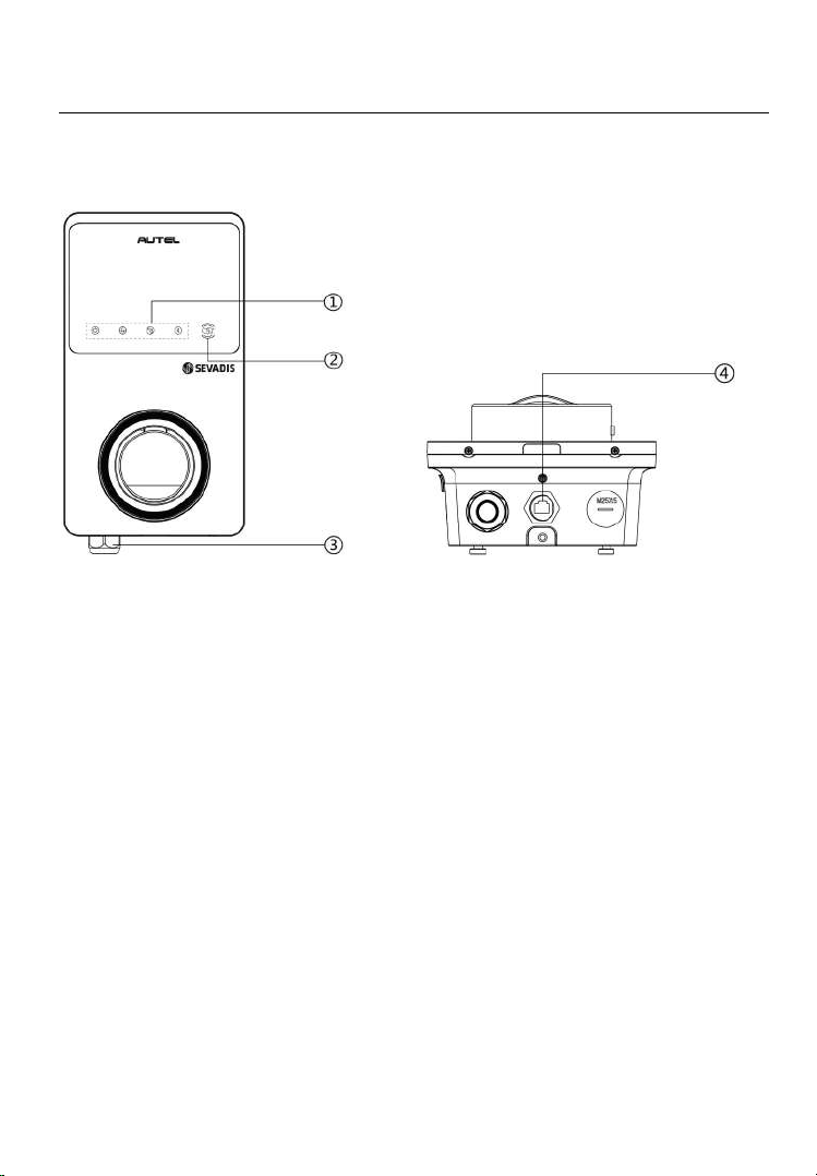
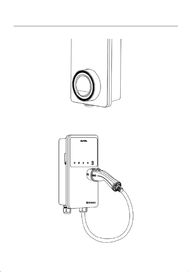
2.1 Product Overview
MaxiCharger AC Wallbox
1. LED Indicators (from left to right):
Power LED
Internet Connection LED
Charging LED
Bluetooth Connection LED
2. RFID Reader
3. AC Input Cable Gland
4. RJ45 Ethernet Port
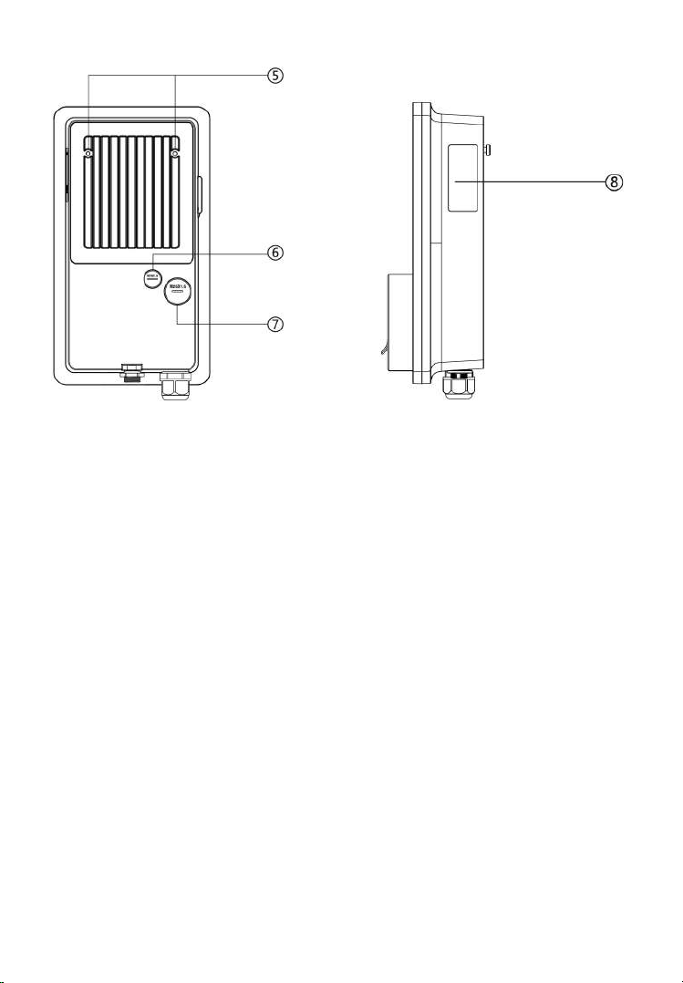
5
5. Mounting Screws
6. Rear Entry Signal Conduit Plug
7. Rear Entry Power Conduit Plug
8. Product Label

6
LED Description
LED Description
Power LED
Solid Green: The MaxiCharger is on.
Off: The MaxiCharger is off.
Flashing Yellow: Data is being transmitted and/or
firmware is upgrading.
Solid Yellow: Firmware upgrade has failed.
Solid Blue: Data transmission has failed; will turn
solid green in five seconds (see above).
Internet
Connection
LED
Solid Green: The MaxiCharger is connected to the
Internet via Wi-Fi, LAN or cellular network.
Off: The MaxiCharger is not connected to the Internet.
Charging LED
Solid Blue: An EV is connected.
Flashing Blue: An EV is charging as scheduled.
Flashing Cyan: The charger is reserved.
Flashing Green: An EV is charging.
Solid Orange: A recoverable error has occurred.
Solid Green: An EV is fully charged.
Off: No EV connected.
Solid Red: An irrecoverable error has occurred.
(Please contact support.)
Bluetooth
Connection
LED
Flashing Green: The MaxiCharger is connected to a
mobile device via Bluetooth.
Flashing Blue: The MaxiCharger is connected to VCI
(Vehicle Communication Interface) via Bluetooth.
Flashing Cyan: The MaxiCharger is connected to a
mobile device and a VCI device simultaneously via
Bluetooth.
Off: The MaxiCharger is not connected via Bluetooth.
7
2.2 Options
Socket, Type 2
Tethered, Type 2

8
SIM Card Socket
(Available on chargers with 4G function.)

9
2.3 Specifications
Item Description
Product
Information
Charging Type Mode 3 charging
Input/Output Power
Rating and Current
Single-phase up to 7.4 kW/32 A
Three-phase up to 22 kW/32 A
Protection
The charger has an integrated
Type A AC 30 mA and DC 6 mA
RCD.
Input/Output Voltage
230 V ±10%, single phase
400 V ±15%, three phase
50 Hz
Network Type TT, TN, and TNCS
General
Characteristics
IP and IK Rating Tethered version: IP65; IK08
Socket version: IP54; IK08
Operating Altitude 2,000 m
Operating
Temperature Range
-40 °C to + 55 °C
Storage
Temperature Range
-40 °C to + 85 °C
Mounting Wall or floor using a pedestal
Dimensions
(H × W × D)
Tethered: 336 x 187 x 85 mm
Socket: 336 × 187 × 115 mm

10
Item Description
User Interface
Status Indication LED
App
User Interface Autel Charge app
Connectivity
4G
Bluetooth
Wi-Fi
Ethernet
Communications
Protocols OCPP 1.6J
User Authentication
App
RFID card
QR code
Software Update
Software Update
OCPP 1.6J
App
Web portal
Certifications
and Standards
Safety Standards
IEC/EN 61851-1, EN 62311,
EN 62479, IEC/EN 62955
Certifications CE, TUV to BSI 7671, UKCA
Warranty 36 months

11
3 Installation
3.1 Prepare for Installation
3.1.1 Preliminary Requirements
All required permits have been acquired in accordance with the local
regulations.
The AC input cable is available.
There is no voltage on the AC input cable throughout the installation
procedure.
3.1.2 Unpack the Charger
1. Open the box.
2. Remove the charger from the box.
3. Remove all packaging material from the charger.
4. Make sure that all parts are delivered according to the order.
5. Inspect the charger and the parts for installation for damage. If you find
damage or the parts are not consistent with the order, contact your local
dealer.
3.1.3 Prepare for Installation
Install the charger on a flat and vertical surface capable of supporting its
weight (e.g. a finished brick or concrete wall, a pedestal, etc.). The maximum
weight of a charger is about 6 kg (13 lbs.).
Install the charger in a location that allows the charge cable to remain within
its bending tolerance.
The recommended installation height is between 700 and 1500 mm (28 and
59 inches).
Position the charger in a location where it is not vulnerable to being damaged.

12
3.2 Mechanical Installation
IMPORTANT
1. Prior to installation, ensure that you have all the tools and parts required for
the installation. Refer to section 3.2.1 or the Packing List.
2. The charger should only be installed by personnel who are trained and
qualified to work on electrical systems.
3. The packaging does not necessarily include all the tools required.

13
3.2.1 Parts and Tools
14
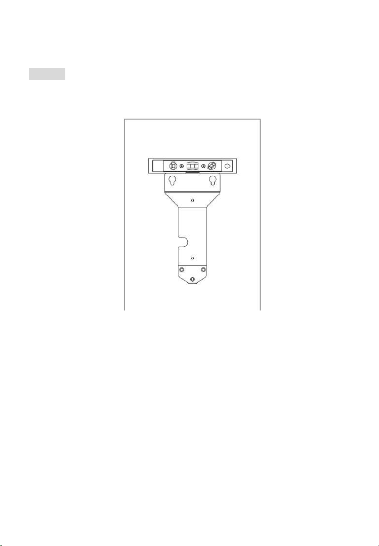
3.2.2 Install the Charger
STEP 1
1. Place the wall dock on the wall and level it using a spirit level or a ruler.
Figure 3-1 Levelling the Wall Dock
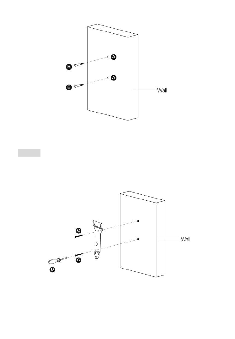
2. Mark the two lower mounting holes (A) with a marker or pencil and drill two
8 mm holes.
3. Insert two 8 mm diameter wall plugs (B) into the lower mounting holes.
15
Figure 3-2 Inserting the Wall Plugs
STEP 2
1. Attach the wall dock to the mounting location by screwing two M6 x 50 screws
(C) into the lower mounting holes.
2. Tighten the two M6 x 50 screws using the screwdriver type PH2 (D).
Figure 3-3 Attaching the Wall Dock
Table of contents


