SEW-Eurodrive MOVIFIT SNI UFF41B User manual

Drive Technology \ Drive Automation \ System Integration \ Services
Manual
MOVIFIT
®
SNI
Fieldbus Gateway UFF41B for MOVIGEAR
®
SNI
Edition 05/2009 16810414 / EN

SEW-EURODRIVE—Driving the world

Manual – MOVIFIT® SNI Fieldbus Gateway UFF41B for MOVIGEAR® SNI 3
1 General Information ............................................................................................... 4
1.1 How to use the manual .................................................................................. 4
1.2 Structure of the safety notes .......................................................................... 4
1.3 Rights to claim under limited warranty ........................................................... 5
1.4 Exclusion of liability........................................................................................ 5
1.5 Copyright notice ............................................................................................. 5
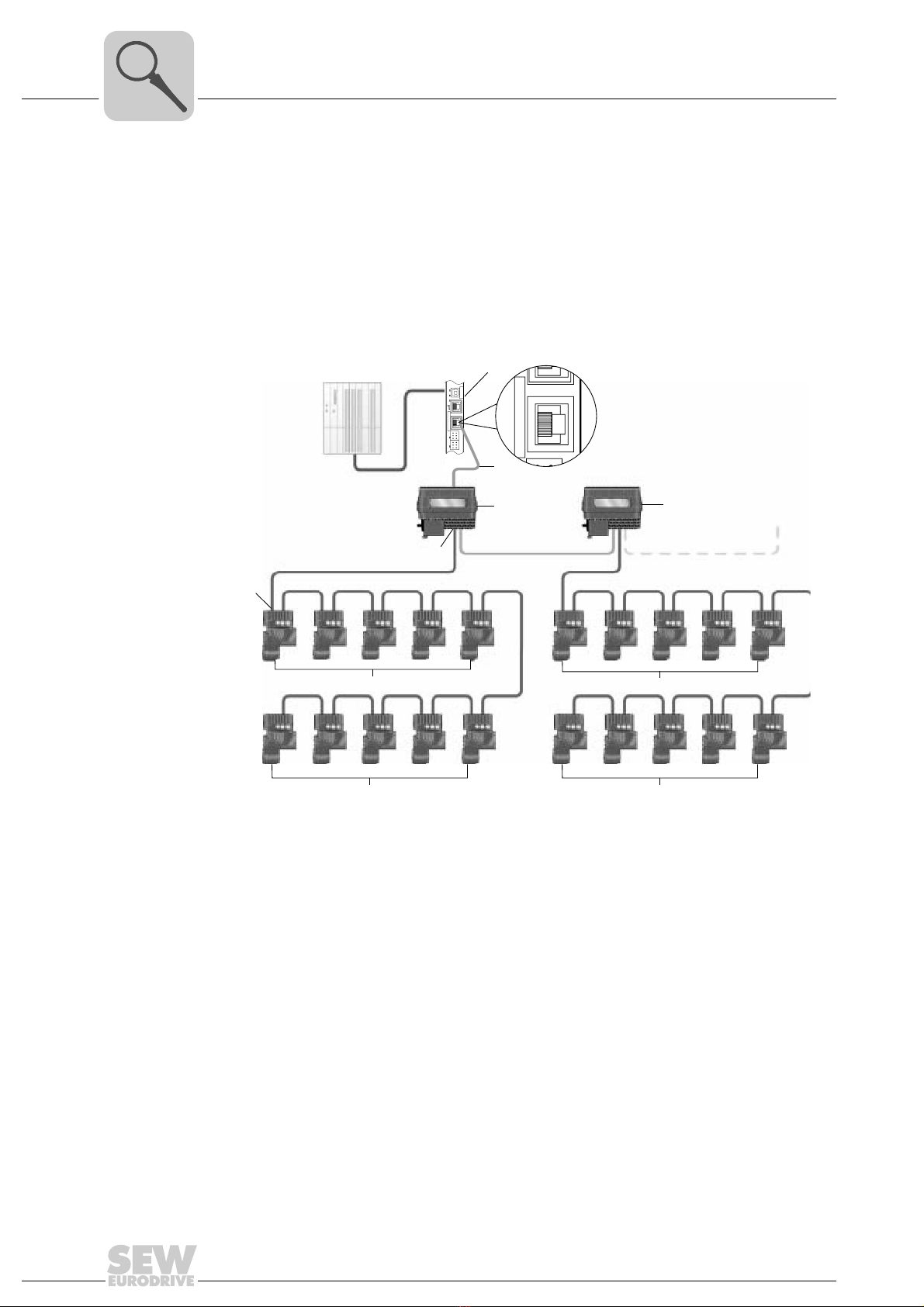
2 System Description................................................................................................ 6
2.1 Field of application ......................................................................................... 6
3 Project Planning..................................................................................................... 7
3.1 Requirements................................................................................................. 7
3.2 Required devices ........................................................................................... 7
3.3 Project planning information........................................................................... 7
3.4 Addressing ..................................................................................................... 7
3.4.1 Important notes ................................................................................... 7
3.4.2 Addressing options of the UFF41B fieldbus gateway ......................... 8
3.4.3 MOVIFIT®SNI via Address Editor .................................................... 16
3.5 Description of functions................................................................................ 19
3.5.1 Possible MOVIGEAR®functions ...................................................... 19
3.6 Process data assignment for fieldbus control .............................................. 20
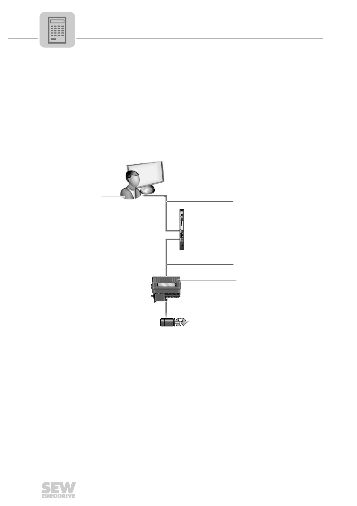
4 Installation ............................................................................................................ 25
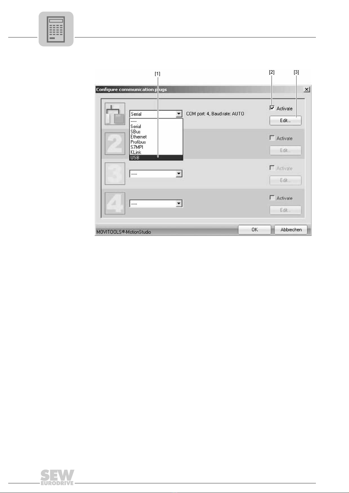
4.1 Plug-in for MOVITOOLS®MotionStudio ...................................................... 25
5 Startup................................................................................................................... 28
5.1 General information ..................................................................................... 28
5.2 SNI gateway configuration .......................................................................... 28
5.3 Process data monitor with integrated control function ................................. 35
5.4 Diagnostics .................................................................................................. 38
5 Index...................................................................................................................... 40

4Manual – MOVIFIT® SNI Fieldbus Gateway UFF41B for MOVIGEAR® SNI
1How to use the manual
General Information
Manual
1 General Information
1.1 How to use the manual
The manual is part of the product and contains important information on operation and
service. The manual is written for all employees who assemble, install, startup, and
service the product.
The manual must be accessible and legible. Make sure that persons responsible for the
system and its operation, as well as persons who work independently on the unit, have
read through the manual carefully and understood it. If you are unclear about any of the
information in this documentation, or if you require further information, contact SEW-
EURODRIVE.
1.2 Structure of the safety notes
The safety notes in this manual are structured as follows:
Pictogram SIGNAL WORD
Type and source of danger.
Possible consequence(s) if the safety notes are disregarded.
• Measure(s) to prevent the danger.
Pictogram Signal word Meaning Consequences if
disregarded
Example:
General danger
Specific danger,
e.g. electric shock
DANGER Imminent danger Severe or fatal injuries
WARNING Possible dangerous situation Severe or fatal injuries
CAUTION Possible dangerous situation Minor injuries
NOTICE Possible damage to property Damage to the drive system or its
environment
INFORMA-
TION
Useful information or tip.
Simplifies the handling of the
drive system.

Manual – MOVIFIT® SNI Fieldbus Gateway UFF41B for MOVIGEAR® SNI 5
1
Rights to claim under limited warranty
General Information
1.3 Rights to claim under limited warranty
A requirement of fault-free operation and fulfillment of any rights to claim under limited
warranty is that you adhere to the information in the manual. Therefore, read the manual
before you start operating the device.
1.4 Exclusion of liability
You must comply with the information in the manual and the documentation of the units
connected to the fieldbus gateway to ensure safe operation and to achieve the specified
product characteristics and performance features. SEW-EURODRIVE assumes no
liability for injury to persons or damage to equipment or property resulting from non-
observance of the operating instructions. In such cases, any liability for defects is
excluded.
1.5 Copyright notice
© 2009 - SEW-EURODRIVE. All rights reserved.
Copyright law prohibits the unauthorized duplication, modification, distribution, and use
of this document, in whole or in part.

6Manual – MOVIFIT® SNI Fieldbus Gateway UFF41B for MOVIGEAR® SNI
2Field of application
System Description
2 System Description
2.1 Field of application
MOVIFIT®SNI [3] can be operated together with the UFF41B fieldbus gateway [1] if you
want to connect a drive system with MOVIGEAR®SNI [6] to a PROFIBUS or DeviceNet
fieldbus system. Configuration and parameter setting is carried out using a plug-in in
MOVITOOLS®MotionStudio.
65997XX
[1] UFF41B fieldbus gateway with SD card OMG42B
[2] Ethernet connection between UFF41B:X37 fieldbus gateway and MOVIFIT®SNI plug connector X1
or X2 (or terminal X3)
[3] MOVIFIT®SNI with Ethernet connection to the next MOVIFIT®SNI
[4] MOVIFIT®SNI, terminal X20:1 – 4
[5] MOVIGEAR®SNI, terminal X1:L1, L2, L3
[6] MOVIGEAR®SNI
[1]
[3]
[3]
[4]
[5]
[2]
[6 ]
[6] [6]
[6]
UFF41B
X35
X36
X37
Version
1
2
3
1
3
4
2
1
2
3
1
2
3
1
2
3
X32X33
S1
L1 L2 L3 L5
XM L4
X37
11
S1
XM

Manual – MOVIFIT® SNI Fieldbus Gateway UFF41B for MOVIGEAR® SNI 7
3
Requirements
Project Planning
3 Project Planning
3.1 Requirements
PC and software The UFF41B fieldbus gateway for MOVIGEAR®SNI is taken into operation using a plug-
in in the SEW software MOVITOOLS®MotionStudio from version 5.6 and higher. In
order to use MOVITOOLS®MotionStudio, you need a PC with one of the following
operating systems: Windows®95, Windows®98, Windows®NT 4.0, Windows®2000 or
Windows®XP.
3.2 Required devices
The application can be implemented with the following devices:
• UFF41B fieldbus gateway with OMG42B SD-card for connection to a PROFIBUS or
DeviceNet fieldbus system
• MOVIFIT®SNI type MTN11A000-503-E4-.. (standard design)
• MOVIGEAR®SNI (standard design)
3.3 Project planning information
Depending on the selected process data profile (1, 2 or 3 PD per drive, 1 or 2 PD per
MOVIFIT®SNI), you can control up to 6 MOVIFIT®SNI in conjunction with 57
MOVIGEAR®SNI drive systems via fieldbus gateway. The various profiles can be
combined depending on the functions required in the driveline. It is important during the
project planning for a system that the required functions (process data profiles) can be
covered by the process data words available. If the number of drivelines requires more
than 64 process data words, more than one fieldbus gateway will have to be used.
3.4 Addressing
3.4.1 Important notes
Select the IP addresses of the fieldbus and MOVIFIT®SNI in such a way that they are
located in the same subnet. Besides, you have to enter the complete subnet mask and
address of the standard gateway.
The IP addresses of the fieldbus gateway, of MOVIFIT®SNI, and of the PC used for
setting the parameters must differ in the range defined in the subnet and must be
unequal 0 or 255 in the last byte.

8Manual – MOVIFIT® SNI Fieldbus Gateway UFF41B for MOVIGEAR® SNI
3Addressing
Project Planning
3.4.2 Addressing options of the UFF41B fieldbus gateway
You have two options to set up the engineering access to the UFF41B fieldbus gateway:
• Via USB interface (X35) (see section "Communication via USB")
• Via Ethernet interface (X37) (see section "Communication via Ethernet")
Communication via USB (direct)
Connecting the
unit with the PC
using an USB
connection cable
The illustration shows how the unit (in the example a fieldbus gateway [3]) is connected
with the PC [1] using a USB connection cable [2]. It also shows how the fieldbus gateway
[3] is connected with the lower-level unit [5].
Do the following to connect the UFx41B fieldbus gateway with the PC and lower-level
units:
1. Plug the Aconnector of the USB cable [2] into a free USB port on your PC [1].
2. Plug the Bconnector of the USB cable [2] into the USB port (X35 with UFF41B) on
your fieldbus gateway [3].
3. Connect the SBus interface of the fieldbus gateway [3] with the SBus interface of the
lower-level unit [5].
65686AXX
[1] PC with USB interface
[2] USB connection cable
[3] Fieldbus gateway (UFx41 in the example)
[4] Ethernet connection between fieldbus gateway and lower-level unit
[5] Lower-level unit (MOVIAXIS®SNI in the example)
[1]
[5]
[3]
[2]
[4]
1
5

Manual – MOVIFIT® SNI Fieldbus Gateway UFF41B for MOVIGEAR® SNI 9
3
Addressing
Project Planning
Installing the driver Before you can communicate with the unit via USB, you have to install the required
driver file from the installation path of MOVITOOLS®MotionStudio.
Follow the instructions below to install the driver for USB communication:
1. Connect the unit to a free USB port on your PC.
Your PC will detect the new hardware and launch the hardware wizard.
2. Follow the instructions of the hardware wizard.
3. Click on [Browse] and go to the MOVITOOLS®MotionStudio installation folder.
4. Enter the following path:
"..\Program Files\SEW\MotionStudo\Driver\SEW_USBWIN32_051120"
5. Click the [Next] button to install the driver.
Configuring USB
communication
You need a USB connection between your PC and the units you want to configure.
Proceed as follows to configure USB communication:
1. Click on "Configure communication plugs" [1] in the toolbar.
64341AXX
[1] "Configure communication plugs" icon

10 Manual – MOVIFIT® SNI Fieldbus Gateway UFF41B for MOVIGEAR® SNI
3Addressing
Project Planning
Doing so will open the "Configure communication plugs" window.
2. From the selection field [1], choose the communication type "USB".
In the example, "USB" is activated as the communication type for the first
communication channel [2].
3. Press the [Edit] button [3] on the right side of the "Configure communication plugs"
window.
64743AEN
[1] "Communication type" selection field
[2] "Activate" check box
[3] [Edit] button

Manual – MOVIFIT® SNI Fieldbus Gateway UFF41B for MOVIGEAR® SNI 11
3
Addressing
Project Planning
This will display the settings for the "USB" communication type.
4. Change the set communication parameters if necessary. When doing so, refer to the
detailed description of the communication parameters.
USB communica-
tion parameters
The following table describes the communication parameters for the USB communica-
tion channel:
12110AEN
Communication parameters Description Note
Timeout Waiting time in milliseconds that
the master waits for a response
from a slave after it has sent a
request.
Default setting: 350 ms

12 Manual – MOVIFIT® SNI Fieldbus Gateway UFF41B for MOVIGEAR® SNI
3Addressing
Project Planning
Communication via Ethernet
Connecting the
Ethernet interface
of UFx41B to the
PC
The following figure shows the connection between the PC/laptop [1] and the UFx41B
[4].
The UFx41B can be connected either directly to the PC or via an Ethernet network.
The Ethernet interface X37 supports auto crossing and auto negotiation for baud rate
and duplex mode. Set the IP parameters of UFF41B as described in the chapter
"Addressing the fieldbus gateways and MOVIFIT®SNI".
Adjusting the
engineering PC to
the network
(address)
To set the engineering PC appropriately for the network (addressing), proceed as
follows:
1. Under [Start] / [Settings] / [Network and Dial-up Connections], select the required PC
interface.
2. Select "Properties" from the context menu.
3. Activate the "Internet protocol (TCP/IP)" check box.
4. Click on the "Properties" button.
5. For the subnet mask and standard gateway, enter the same IP addresses that are
used for other Ethernet stations in this local network.
6. For the engineering PC, enter an IP address that meets the following conditions:
• In the blocks that define the network, the address section of the engineering PC
must correspond with the address section of the other Ethernet stations.
• In the blocks that define the station, the address section of the engineering PC
must be different from the address section of the other Ethernet stations.
• Do not assign the values "0", "4", "127" and "255" in the last block.
64420AXX
UFF41B
X35
X36
X37
Version
1
2
3
1
3
4
2
1
2
3
1
2
3
1
2
3
X32X33
S1
L1 L2 L3 L5
XM L4
X37
S1
[4]

Manual – MOVIFIT® SNI Fieldbus Gateway UFF41B for MOVIGEAR® SNI 13
3
Addressing
Project Planning
Configuring the
communication
channel via
Ethernet
Proceed as follows to configure a communication channel for Ethernet:
1. Click on [Configure communication plugs] [1] in the toolbar.
2. This opens the "Configure communication plugs" window. From the list [1], select
"Ethernet" as the communication type. In the example, "Ethernet" is activated as the
communication type for the first communication channel [2].
3. Press the [Edit] button [3] in the right part of the window. This displays the settings
for the "Ethernet" communication type.
4. Set up the SMLP protocol. To do so, select the "SMLP settings" tab.
5. Set the parameters. Follow the instructions described in the section "Setting
parameters for SMLP".
INFORMATION
In the IP address of the subnet mask (e.g. 255.255.255.0), the values in the blocks
have the following meaning:
• "255" defines the address of the network where the stations are located.
• "0" defines the address of the actual station to differentiate it from the others.
64341AXX
64351AEN

14 Manual – MOVIFIT® SNI Fieldbus Gateway UFF41B for MOVIGEAR® SNI
3Addressing
Project Planning
Setting communication parameters for SMLP
The following table describes the communication parameters for SMLP:
To set up communication parameters for communicating via Ethernet, proceed as
follows:
1. If necessary, change the preset communication parameters. Refer to the detailed
description of the communication parameters for SMLP.
INFORMATION
SMLP stands for Simple MOVILINK®Protocol. It is the device protocol from SEW-
EURODRIVE.
Communication parameters of
the simple MOVILINK®protocol
Description Note
Timeout Waiting time in [ms] that the client
waits for a response from the
server after it has made a
request.
• Default setting: 1000 ms
• Increase the value as
required if a delay in
communication is causing
malfunctions.
Broadcast IP address IP address of the local network
segment within which the unit
scan is carried out.
In the default setting, the unit
scan only detects units that are in
the local network segment.
IP address of SMLP server IP address of the SMLP server or
of other units that are to be inclu-
ded in the unit scan but are out-
side the local network segment.
• Enter the IP address of units
that are to be included in the
unit scan but are outside the
local network segment.
Excluded IP address IP addresses of units that should
not be included in the unit scan.
Enter the IP address of units that
should not be included in the unit
scan. These can be units that are
not ready for communication (for
example because they have not
been started up yet).
INFORMATION
During a unit scan, the system recognizes only units that are in the same (local)
network segment as the PC that is running on MOVITOOLS®MotionStudio.
• If you have units that are OUTSIDE the local network segment, add the IP
addresses of these units to the list of SMLP servers.

Manual – MOVIFIT® SNI Fieldbus Gateway UFF41B for MOVIGEAR® SNI 15
3
Addressing
Project Planning
2. To add an IP address, open the context menu and select [Add IP address] [1].
3. Add IP address [2]
DIP switch S1
default IP
address With DIP switch S1, you can set a default IP address for the Ethernet connection (X37).
The set IP address will be applied in the next boot process.
64352AEN
S1 switch setting Meaning
Top IP pa rame ter :
• IP address: 192.168.10.4
• Subnet mask: 255.255.255.0
• Standard gateway: 1.0.0.0
Bottom The IP parameters defined on the memory card of the UFF41B gateway are used.
The IP parameters for engineering interface X37 are entered in the file "...\Sys-
tem\NetConfig.cfg" in the section "Ethernet 2". You can adjust the file using a text
editor (e.g. Notepad).

16 Manual – MOVIFIT® SNI Fieldbus Gateway UFF41B for MOVIGEAR® SNI
3Addressing
Project Planning
3.4.3 MOVIFIT®SNI via Address Editor
Opening the
Address Editor
You can use the Address Editor once MOVITOOLS®MotionStudio has been installed.
Do the following to open the Address Editor:
1. Close MOVITOOLS®MotionStudio.
2. Open the Address Editor in the WINDOWS®start menu by following the path below:
Start\Program\SEW\MOVITOOLS MotionStudio\Address Editor
(Address Tool)
Searching for
Ethernet stations
You can use the Address Editor to find Ethernet stations in a network. This is especially
useful for finding recently added Ethernet stations. The Address Editor also helps you
to locate the Ethernet interface of the Ethernet stations that were found.
To search for Ethernet stations and locate hardware, proceed as follows:
1. Make sure that MOVIFIT®SNI is connected with the PC via an Ethernet network.
Select "Ethernet" as the interface for PC and unit. To do so, click on the
corresponding option field in the lower part of the window.
2. Click [Next] to confirm your selection and proceed to the next dialog.
3. Wait for the network scan to start automatically. The default setting for the waiting
time (scan timeout) is 3 seconds [2]
12132AEN

Manual – MOVIFIT® SNI Fieldbus Gateway UFF41B for MOVIGEAR® SNI 17
3
Addressing
Project Planning
You can also start the network scan manually as follows:
• If you have several network cards installed in your PC, select the required card.
To do so, click the "Select network card" icon [3] in the toolbar.
• Click the "Start network scan" icon [1] in the toolbar.
As a result, the current addresses of all Ethernet stations in the connected network
will be displayed and the link/act LED of the first Ethernet interface of the Ethernet
station will flash.
64348AXX
[1] "Start network scan" icon
[2] "Scan timeout" edit box
[3] "Select network card" icon
[1] [2] [3]

18 Manual – MOVIFIT® SNI Fieldbus Gateway UFF41B for MOVIGEAR® SNI
3Addressing
Project Planning
Adjusting located
Ethernet stations
to the network
(address)
To set the located Ethernet stations appropriately for the network (addressing), proceed
as follows:
1. Double-click on the "Communication parameters" window of the respective unit [1] to
adjust the IP parameters of an Ethernet station to the network.
The following fields can then be edited:
• IP address of the Ethernet station
• IP address of the subnet mask
• IP address of the standard gateway
• DHCP startup configuration (if supported by the unit)
2. Transmit the address changes to the Ethernet station. To do so, click the [Download]
button [2].
65517AEN
[1] "Communication parameters" window range
[2] "Download" button
[1]
[2]

Manual – MOVIFIT® SNI Fieldbus Gateway UFF41B for MOVIGEAR® SNI 19
3
Description of functions
Project Planning
3.5 Description of functions
3.5.1 Possible MOVIGEAR®functions
The MOVIGEAR®functions are used to control a drive individually. The different
functions is assigned a specific number of process data words. This means the
individual drives share the 64 available process data (PD).
•1 PD drive function
The 1 PD drive function allows for controlling a MOVIGEAR®with fixed speeds by
means of a process data word. You can configure 4 ramp sets and 6 fixed speeds by
clicking the [Ramps] and [Fixed speeds] buttons.
•2 PD drive function
The 2 PD drive function allows for controlling a MOVIGEAR®with a user-specific
speed by means of two process data words. You can configure 4 ramp sets by
clicking the [Ramps] button.
•3 PD drive function
The 3 PD drive function allows for controlling a MOVIGEAR®with a user-specific
speed by means of three process data words. The third process data word can be
used for controlling the local inputs/outputs or for displaying the actual current. You
can configure 4 ramp sets by clicking the [Ramps] button.
•1(2) PD axis function
The 1(2) PD axis function allows for controlling the positioning functions integrated
in MOVIGEAR®. This is achieved either by means of fixed speeds or by a user-
defined speed. You can configure 4 ramp sets by clicking the [Ramps] button. The
relevant positioning function is configured in the MOVIVISION®software (see
MOVIGEAR®SNI system manual, chapter 11).
12134AEN
12135AEN
12136AEN
12137AEN

20 Manual – MOVIFIT® SNI Fieldbus Gateway UFF41B for MOVIGEAR® SNI
3Process data assignment for fieldbus control
Project Planning
3.6 Process data assignment for fieldbus control
The fieldbus gateway can be integrated into a PROFIBUS controller using the GSD file
"SEW_600D.GSD", or into a DeviceNet controller using the EDS file
"SEW_GATEWAY_UFF.EDS".
INFORMATION
The latest version of the GDS and EDS files are available on the SEW homepage
(http://www.sew-eurodrive.com) under the heading "Software".
Gateway 1 PD
PO PI Assignment
Bit 0 SNI controller 1 timeout
Bit 1 SNI controller 2 timeout
Bit 2 SNI controller 3 timeout
Bit 3 SNI controller 4 timeout
Bit 4 SNI controller 5 timeout
Bit 5 SNI controller 6 timeout
Bit 6 Warning
Bit 7 Error
Bit 8 - 15
• Status (if bit 6 = bit 7 = FALSE)
• Error number (if bit 7 = TRUE)
• Warning (if bit 6 = TRUE AND bit 7 = FALSE)
Other manuals for MOVIFIT SNI UFF41B
1
Table of contents
Other SEW-Eurodrive Gateway manuals