SEW movigear sni-b User manual
Drive Technology \ Drive Automation \ System Integration \ Services
Operating Instructions
Mechatronic Drive System
MOVIGEAR
®
SNI-B
Single Line Network Installation
Edition 12/2013 20254547 / EN

SEW-EURODRIVE—Driving the world

Operating Instructions – MOVIGEAR® SNI-B 3
Contents
Contents
1 General information ............................................................................................ 6
1.1 How to use this documentation................................................................... 6
1.2 Structure of the safety notes ....................................................................... 6
1.3 Rights to claim under warranty ................................................................... 7
1.4 Exclusion of liability..................................................................................... 7
1.5 Copyright..................................................................................................... 7
1.6 Product names and trademarks.................................................................. 7
2 Safety notes......................................................................................................... 8
2.1 General information .................................................................................... 8
2.2 Target group ............................................................................................... 8
2.3 Designated use ........................................................................................... 9
2.4 Transportation, storage ............................................................................ 9
2.5 Installation................................................................................................. 10
2.6 Electrical connection ................................................................................. 10
2.7 Safe disconnection.................................................................................... 10
2.8 Operation .............................................................................................. 11
3 Unit structure..................................................................................................... 12
3.1 MOVIGEAR®drive unit ........................................................................ 12
3.2 Shaft types .............................................................................................. 13
3.3 Housing mounting ................................................................................... 14
3.4 Cable entry positions ............................................................................. 15
3.5 Example nameplate and type designation of the drive unit ................... 16
3.6 Electronics ............................................................................................ 17
3.7 Application options .............................................................................. 19
3.8 Example nameplate and type designation of electronics ...................... 21
3.9 MOVIGEAR®with optional design for wet areas (/WA option) ............. 23
4 Mechanical installation..................................................................................... 25
4.1 Installation notes ................................................................................... 25
4.2 Required tools and resources ................................................................... 25
4.3 Installation requirements........................................................................... 26
4.4 Setting up the drive unit ............................................................................ 27
4.5 Application options .............................................................................. 31
4.6 Shaft-mounted gear unit with keyway .................................................... 34
4.7 Shaft mounted gear unit with TorqLOC®
(customer shaft without contact shoulder) ............................................. 39
4.8 Shaft mounted gear unit with TorqLOC®
(customer shaft with contact shoulder) .................................................. 45
4.9 Shaft-mounted gear unit with TorqLOC®–
Removal, cleaning, lubrication ............................................................... 51
4.10 Installing the protective cover ................................................................ 53
4.11 Torque arm ........................................................................................... 55
4.12 Tightening torques ............................................................................... 56
4.13 Drive units with optional version for use in wet areas ............................ 59

4Operating Instructions – MOVIGEAR® SNI-B
Contents
5 Electrical installation ........................................................................................ 66
5.1 Installation planning considering EMC aspects .................................... 66
5.2 Installation instructions.............................................................................. 68
5.3 Installation topology (example) ............................................................. 73
5.4 Terminal assignment .............................................................................. 74
5.5 Connecting MOVIGEAR®drive units ..................................................... 76
5.6 Cable routing and shielding .................................................................... 77
5.7 EMC cable glands ................................................................................. 82
5.8 Required power leads .......................................................................... 83
5.9 Plug connectors .................................................................................... 85
5.10 Assignment of optional plug connectors ............................................... 90
5.11 Application options .............................................................................. 99
6 Startup.............................................................................................................. 101
6.1 Startup notes ....................................................................................... 101
6.2 Prerequisties for startup ...................................................................... 102
6.3 Description of DIP switches ................................................................ 103
6.4 Startup procedure .............................................................................. 105
6.5 Starting up the GIO13B application option ........................................ 107
6.6 Disabling DynaStop®for startup purposes ........................................... 110
7 Operation of MOVITOOLS®MotionStudio ................................................ 111
7.1 About MOVITOOLS®MotionStudio ........................................................ 111
7.2 First steps .............................................................................................. 111
7.3 Connection mode.................................................................................... 114
7.4 Executing functions of the units .............................................................. 116
8 Parameters ................................................................................................... 118
8.1 Overview of parameters of the command PCB ..................................... 118
8.2 Overview of parameters for application options ................................... 120
8.3 Overview of power section parameters ................................................. 122
8.4 Description of command PCB parameters.............................................. 135
8.5 Description of application option parameters ........................................ 138
8.6 Description of power section parameters................................................ 141
9 Operation ..................................................................................................... 171
9.1 Local mode (only in conjunction with optional plug connector) ............. 171
9.2 DynaStop®............................................................................................ 173
9.3 Deactivating DynaStop®..................................................................... 173
10 Service ............................................................................................................. 176
10.1 Malfunctions of the mechanical MOVIGEAR®drive ............................. 176
10.2 Evaluating error messages ................................................................. 177
10.3 Switch-off responses ............................................................................ 178
10.4 Reset of error messages .................................................................. 178
10.5 Description of status and operating displays ...................................... 179
10.6 Error table ........................................................................................... 182
10.7 Unit replacement ................................................................................. 184
10.8 SEW-EURODRIVE Service ................................................................... 186

Operating Instructions – MOVIGEAR® SNI-B 5
Contents
10.9 Shutdown ............................................................................................ 187
10.10 Storage ................................................................................................... 187
10.11 Extended storage.................................................................................... 188
10.12 Disposal ............................................................................................... 190
11 Inspection and maintenance.......................................................................... 191
11.1 Determining the operating hours ......................................................... 191
11.2 Inspection and maintenance intervals .................................................. 192
11.3 Lubrication change intervals ................................................................ 193
11.4 Inspection and maintenance work .......................................................... 194
12 Technical data and dimension sheets .......................................................... 202
12.1 Technical data ..................................................................................... 202
12.2 Technical data of application options ................................................ 205
12.3 Integrated BW1 braking resistor ........................................................... 207
12.4 DynaStop®deceleration torque ............................................................ 208
12.5 Torque characteristics ........................................................................... 209
12.6 Surface protection ................................................................................ 217
12.7 Variant for use in wet areas ................................................................. 219
12.8 Screw fittings........................................................................................... 223
12.9 Connection cables .......................................................................... 224
12.10 Mounting positions ............................................................................... 226
12.11 Lubricants ............................................................................................ 228
12.12 Design notes for gear units with hollow shaft and key ......................... 231
12.13 Dimension drawings ........................................................................... 233
13 EC declaration of conformity ....................................................................... 242
14 Address list...................................................................................................... 243
Index................................................................................................................. 255

6Operating Instructions – MOVIGEAR® SNI-B
1How to use this documentation
General information
1 General information
1.1 How to use this documentation
The documentation is an integral part of the product and contains important information
on operation and service. The documentation is written for all employees who assemble,
install, start up, and service this product.
The documentation must be accessible and legible. Make sure that persons responsible
for the system and its operation, as well as persons who work independently on the unit,
have read through the documentation carefully and understood it. If you are unclear
about any of the information in this documentation, or if you require further information,
contact SEW-EURODRIVE.
1.2 Structure of the safety notes
1.2.1 Meaning of signal words
The following table shows the graduation and meaning of the signal words for safety
notes, warnings regarding potential risks of damage to property, and other notes.
1.2.2 Design of the section-related safety notes
Section-related safety notes do not apply to a specific action, but to several actions per-
taining to one subject. The symbols used either indicate a general hazard or a specific
hazard.
This is the formal structure of a safety note for a specific section:
1.2.3 Design of the embedded safety notes
Embedded safety notes are directly integrated into the instructions just before the de-
scription of the dangerous action.
This is the formal structure of an embedded safety note:
•SIGNAL WORD! Type and source of hazard.
Possible consequence(s) if disregarded.
– Measure(s) to prevent the hazard.
Signal word Meaning Consequences if disregarded
DANGER! Imminent hazard Severe or fatal injuries
WARNING! Possible dangerous situation Severe or fatal injuries
CAUTION! Possible dangerous situation Minor injuries
NOTICE Possible damage to property Damage to the drive system or its envi-
ronment
INFORMATION Useful information or tip: Simpli-
fies handling of the drive sys-
tem.
SIGNAL WORD!
Type and source of danger.
Possible consequence(s) if disregarded.
• Measure(s) to prevent the danger.

Operating Instructions – MOVIGEAR® SNI-B 7
1
Rights to claim under warranty
General information
1.3 Rights to claim under warranty
A requirement of fault-free operation and fulfillment of any rights to claim under limited
warranty is that you adhere to the information in the documentation. Therefore read the
documentation before you start working with the unit.
1.4 Exclusion of liability
You must comply with the information contained in this documentation to ensure safe
operation and to achieve the specified product characteristics and performance fea-
tures. SEW-EURODRIVE assumes no liability for injury to persons or damage to equip-
ment or property resulting from non-observance of these operating instructions. In such
cases, any liability for defects is excluded.
1.5 Copyright
© 2013 SEW-EURODRIVE. All rights reserved.
Unauthorized duplication, modification, distribution or any other use of the whole or any
part of this documentation is strictly prohibited.
1.6 Product names and trademarks
All product names in this documentation are trademarks or registered trademarks of
their respective titleholders.

8Operating Instructions – MOVIGEAR® SNI-B
2General information
Safety notes
2 Safety notes
The following basic safety notes must be read carefully to prevent injury to persons and
damage to property. The operator must ensure that the basic safety notes are read and
adhered to. Ensure that persons responsible for the system and its operation, as well as
persons who work independently on the unit, have read through the operating
instructions carefully and understood them. If you are unclear about any of the informa-
tion in this documentation, or if you require further information, please contact SEW-
EURODRIVE.
2.1 General information
Never install damaged products or take them into operation. Submit a complaint to the
shipping company immediately in the event of damage.
During operation, MOVIGEAR®drive units can have live, bare and movable or rotating
parts as well as hot surfaces, depending on their degree of protection.
Removing covers without authorization, improper use as well as incorrect installation or
operation may result in severe injuries to persons or damage to property.
Refer to the documentation for additional information.
2.2 Target group
Only qualified electricians are authorized to install, start up or service the units or
correct unit faults (observing IEC 60364 or CENELEC HD 384 or DIN VDE 0100 and
IEC 60664 or DIN VDE 0110 as well as national accident prevention guidelines).
Qualified electricians in the context of these basic safety notes are all persons familiar
with installation, assembly, startup and operation of the product who possess the
necessary qualifications.
All persons involved in any other work, such as transportation, storage, operation and
disposal, must be trained appropriately.

Operating Instructions – MOVIGEAR® SNI-B 9
2
Designated use
Safety notes
2.3 Designated use
MOVIGEAR®drive units are components intended for installation in electrical systems
or machines.
In case of installation in machines, taking the MOVIGEAR®drive units into operation
(i.e. start of designated operation) is prohibited until it is determined that the machine
meets the requirements stipulated in EC Directive 2006/42/EC (Machinery Directive).
Startup (i.e. the start of designated use) is only permitted under observance of EMC
directive 2004/108/EC (EMC Directive).
MOVIGEAR®drive units comply with the regulations of the Low Voltage Directive
2006/95/EC. The standards given in the declaration of conformity are applied to the
MOVIGEAR®drive units.
You must observe the technical data and information on the connection requirements
as provided on the nameplate and in the documentation.
2.3.1 Safety functions
MOVIGEAR®drive units may not perform safety functions unless these functions are
described and expressly permitted.
2.3.2 Lifting applications
MOVIGEAR®drive units must not be used for lifting applications.
MOVIGEAR®drive units may only be used for inclining tracks after the operator has
performed a risk assessment. Refer to the relevant information in the documentation.
2.4 Transportation, storage
You must observe the notes in the documentation regarding transportation, storage and
proper handling. Use suitable, sufficiently rated handling equipment (e.g. rope guides)
if required. Do not attach any additional loads. Observe climatic conditions in accor-
dance with the documentation.
The following figure shows the eyebolt of MOVIGEAR®drive units:
9007202025361803

10 Operating Instructions – MOVIGEAR® SNI-B
2Installation
Safety notes
2.5 Installation
The units must be installed and cooled according to the regulations and specifications
in the corresponding documentation.
Protect the MOVIGEAR®drive units from improper strain.
The following applications are prohibited unless explicitly permitted:
• Use in potentially explosive atmospheres.
• Use in areas exposed to harmful oils, acids, gases, vapors, dust, radiation, etc.
• Use in non-stationary applications that are subject to mechanical vibration and shock
loads as stated in the documentation for MOVIGEAR®drive units.
Important: MOVIGEAR®drive units and corresponding mount-on parts must not pro-
trude into footways.
2.6 Electrical connection
Working on live parts of MOVIGEAR®drive units is not permitted.
The drive is operated as a generator due to the kinetic energy of the system/machine.
Secure the output shaft against rotation before opening the wiring compartment.
Electrical installation must be carried out in compliance with pertinent regulations (e.g.
cable cross sections, fusing, protective conductor connection). For any additional infor-
mation, refer to the applicable documentation.
You find notes on EMC-compliant installation, such as shielding, grounding, arrange-
ment of filters and routing of lines, in the documentation of the MOVIGEAR®drive units.
The manufacturer of the system or machine is responsible for maintaining the limits es-
tablished by EMC legislation.
Protective measures and protection devices must comply with the regulations in force
(e.g. EN 60204-1 or EN 61800-5-1).
2.7 Safe disconnection
MOVIGEAR®drive units meet all requirements for safe disconnection of power and
electronics connections in accordance with EN 61800-5-1. All connected circuits must
also satisfy the requirements for safe disconnection to ensure reliable isolation.
Operating Instructions – MOVIGEAR® SNI-B 11
2
Operation
Safety notes
2.8 Operation
Systems with integrated MOVIGEAR®drive units must be equipped with additional
monitoring and protection devices according to the applicable safety guidelines, such as
the law governing technical equipment, accident prevention regulations, etc. Additional
protective measures may be necessary for applications with increased potential risk.
Changes to MOVIGEAR®drive units using the operating software are permitted.
The connection boxes must be closed and screwed on before the supply voltages are
connected to MOVIGEAR®drive units.
The unit may still be live and connected to the power supply even if the operation LEDs
and other display elements are no longer illuminated.
Mechanical blocking or internal safety functions of the unit can cause a motor standstill.
Eliminating the cause of the problem or performing a reset may result in the drive re-
starting automatically. If this is not permitted for the driven machine for safety reasons,
disconnect the unit from the supply system before correcting the fault.
Caution: Danger of burns: The surface temperatures of MOVIGEAR®drive units can be
more than 60 °C during operation.
5 minutes
WARNING
Do not touch live components and power connections immediately after separation of
the MOVIGEAR®drive units from the supply voltage because some capacitors might
still be charged.
Severe or fatal injuries.
• Wait at least for 5 minutes after the supply voltage has been switched off.

12 Operating Instructions – MOVIGEAR® SNI-B
3MOVIGEAR®drive unit
Unit structure
3 Unit structure
3.1 MOVIGEAR®drive unit
MOVIGEAR®drive units are made up of 3 core components: gear unit, motor and drive
electronics. These 3 core components are included in one die-cast aluminum housing
(see following figure).
36028799382850955
[1] MOVIGEAR®electronics cover
[2] Connection ring for cable glands
[3] Inspection cover
[4] Output shaft variant (pictured here: hollow shaft with keyway)
[5] Optional cover
MGF..4/XT
[1]
[2]
[3]
[3]
MGF..4
MOVIGEAR
®
B
MOVIGEAR
®
B
MOVIGEAR
®
®
B
MGF..2
[4]
[5]
[5]
[5]
[1]
[2]
[4]
[3]
[4]
[1]
[2]

Operating Instructions – MOVIGEAR® SNI-B 13
3
Shaft types
Unit structure
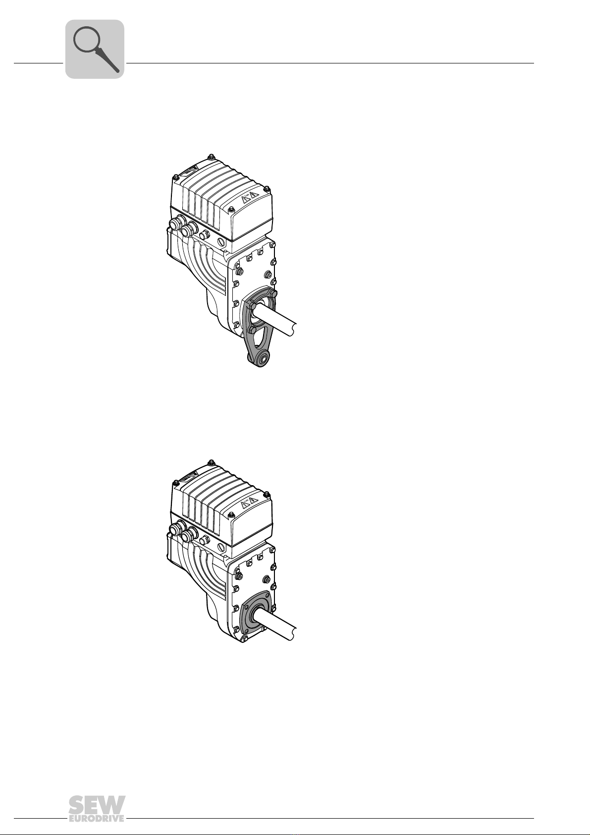
3.2 Shaft types
MOVIGEAR®is available with the following shaft types:
3.2.1 MOVIGEAR®with hollow shaft and keyway (MGFA..)
The following figure shows a MOVIGEAR®unit with hollow shaft and keyway:
3.2.2 MOVIGEAR®with TorqLOC®hollow shaft mounting system (MGFT..)
The following figure shows a MOVIGEAR®unit with TorqLOC®hollow shaft mounting
system
18014401200302603
18014401200304523
14 Operating Instructions – MOVIGEAR® SNI-B
3Housing mounting
Unit structure
3.3 Housing mounting
3.3.1 Torque arm (MGF.T)
The following figure shows the torque arm for MGF.T:
3.3.2 Housing with threads (MGF.S)
The following figure shows the housing type with threads for mounting a torque arm.
This type does not include a centering shoulder, which means it is not suitable for direct
installation to the machine:
18014401200308363
18014401200306443
Operating Instructions – MOVIGEAR® SNI-B 15
3
Cable entry positions
Unit structure
3.4 Cable entry positions
The following cable entries are possible for MOVIGEAR®drive units:
• Position X + 2
– X: 2 x M25 x 1.5 + 2 x M16 x 1.5
– 2: 2 x M25 x 1.5 + 2 x M16 x 1.5
• Position X + 2 + 3
– X: 2 x M25 x 1.5 + 2 x M16 x 1.5
– 2: 2 x M25 x 1.5 + 2 x M16 x 1.5
– 3: 2 x M25 x 1.5 + 2 x M16 x 1.5
• Position X + 3
– X: 2 x M25 x 1.5 + 2 x M16 x 1.5
– 3: 2 x M25 x 1.5 + 2 x M16 x 1.5
• Position 2 + 3
– 2: 2 x M25 x 1.5 + 2 x M16 x 1.5
– 3: 2 x M25 x 1.5 + 2 x M16 x 1.5
3.4.1 Overview
The following figure shows the possible cable entries:
18014401200378763
3
3
X
X
2
2
2
2
RUN
NET DRIVE
MOVIGEAR
®
B
X
3
16 Operating Instructions – MOVIGEAR® SNI-B
3Example nameplate and type designation of the drive unit
Unit structure
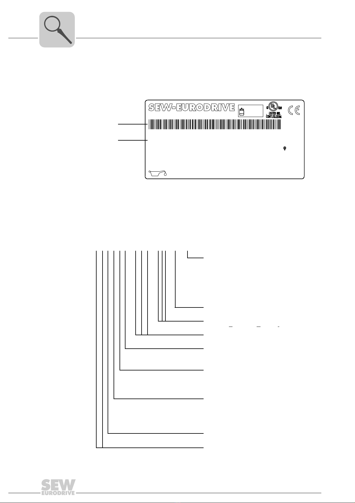
3.5 Example nameplate and type designation of the drive unit
3.5.1 Nameplate
The following figure gives an example of a MOVIGEAR®nameplate. For the structure
of the type designation, refer to chapter "Type designation".
3.5.2 Type designation
The following table shows the type designation of MOVIGEAR®:
18014400877661323
[1] Unique serial number
[2] The bar code on the nameplate (code 39) according to ISO/IEC 16388 represents the unique
serial number (with a period as separator).
76646 Bruchsal/Germany
Nm
°C
n
R
U
N
f
N
Nm
n
A
A
M
A
M
a pk
i
Made in Germany
IM
kg
cos
IP
r/min
Hz
V
13356887
MGFAT2-DSM-SNI-B/DSP
01.1233697403.0001.08
5,4...53,7
37,24
M1,M2,M4,M5,M6 50...60
380...500
65
0,99
1,52
1/10
16.000
CLP HC 220 Synth.Öl/0,55l
0 ... +40
[1]
[2]
3~ EN61800 TENV M.L.
149
220
eff%
86,3
IE4
MGFAS2–DSM–SNI–B/DSP
MOVIGEAR®option
DSP
ECR
XT
IV
WA
=
=
=
=
=
Electrodynamic
deceleration function DynaStop®
Extended control range
Increased torque
Plug connectors
Version for use in wet areas
MOVIGEAR®version
MOVIGEAR®installation technology
SNI = Single Line Network Installation
Motor type
Frame size
2
4
=
=
Torque class 200 Nm
Torque class 400 Nm
Housing mounting
T
S
=
=
Drive with torque arm
Housing with threads for
mounting a torque arm
Shaft type
A
T
=
=
Shaft-mounted gear unit
(hollow shaft with key)
TorqLOC®hollow shaft mounting sys-
tem
Gear unit type
F = Parallel-shaft helical gear units
Product line
MG = MOVIGEAR®

Operating Instructions – MOVIGEAR® SNI-B 17
3
Electronics
Unit structure
3.6 Electronics
3.6.1 MOVIGEAR®electronics cover (inside) and connection box
The following figure shows the connection box and the bottom side of the MOVIGEAR®
electronics cover:
2389525515
[1] Nameplate of drive unit, see following detailed view
2584370315
[2] Connection ring
[3] Plug connector connection unit for MOVIGEAR®electronics cover
[4] MOVIGEAR®electronics cover
[5] Electronics cover nameplate
[6] Cable glands
[7] Screws for PE connection
[8] Line connection L1, L2, L3
[9] Electronics terminal strips
[10] DIP switches S2/1 – S2/4
[11] DIP switches S1/1 – S1/4
[7]
[6] [7] [7][7] [6]
[9]
[8] [10] [11]
[3]
[2]
[1] [4] [5]
[1]
18 Operating Instructions – MOVIGEAR® SNI-B
3Electronics
Unit structure
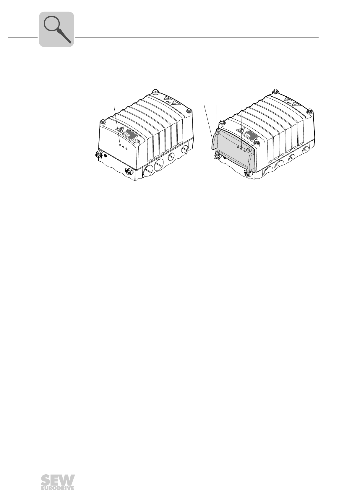
3.6.2 Electronics cover (outside)
The following figure shows the possible variants of the electronic cover using one frame
size as an example:
18014400877430923
A Electronics cover without application slot B Electronics cover with application slot
[1] LED displays [1] Assembly/disassembly handle
[2] Retaining screws (4x)
[3] Application cover
[4] LED displays
NET RUN DRIVE
NET RUN DRIVE
[1] [1] [2] [3] [4]
AB
Operating Instructions – MOVIGEAR® SNI-B 19
3
Application options
Unit structure
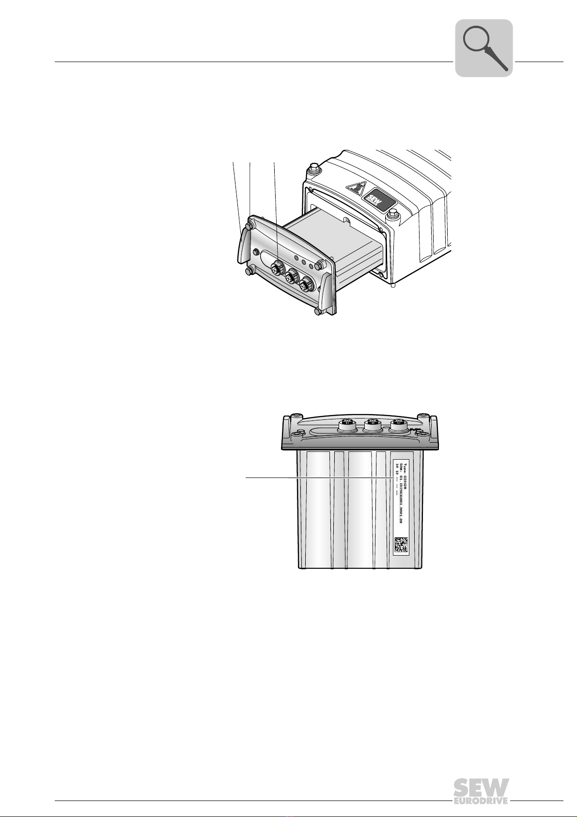
3.7 Application options
3.7.1 GIO12B application option
The following figure shows the GIO12B application option:
The following figure shows the position of the GIO12B nameplate:
9007201622841227
[1] Assembly/disassembly handle
[2] Retaining screws (4x)
[3] M12 plug connector for digital I/Os
18014401210968331
[1] Nameplate
[1] [2] [3]
NET RUN DRIVE
X4 X3 X2 X1
[1]
20 Operating Instructions – MOVIGEAR® SNI-B
3Application options
Unit structure
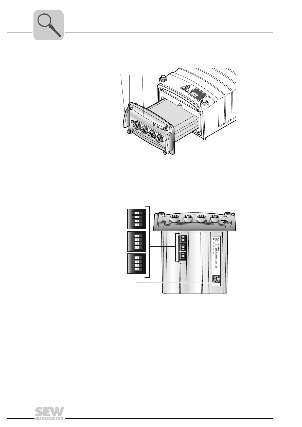
3.7.2 GIO13B application option
The following figure shows the GIO13B application option:
The following figure shows the DIP switches S1 to S3 of the GIO13B application option:
9007201839769867
[1] Assembly/disassembly handle
[2] Retaining screws (4x)
[3] M12 plug connector for digital/analog I/Os
18014401245670283
[1] Nameplate
NETRUN DRIVE
X4 X3 X2 X1
[1] [2] [3]
ON
1234
ON
1234
ON
1234
ON
1234
ON
1234
S1
S2
S3
ON
1234
[1]
Table of contents
Other SEW Servo Drive manuals

Popular Servo Drive manuals by other brands


Mitsubishi Electric
Mitsubishi Electric MR-J5 Series user manual

Lenze
Lenze L-force 9400 Series Hardware manual

Technosoft
Technosoft iPOS80x0 BX-CAN Technical reference

Bosch
Bosch Rexroth IndraDrive Mi Project planning manual

Lenze
Lenze AC Tech PositionServo 940 user manual

Siemens
Siemens SINAMICS V90 operating instructions