SEW 2751 IN User manual
INSTRUCTION MANUAL
2751 IN
INSULATION TESTER

Index
1. Instrument Layout..............................
2. Introduction.........................................
3. Safety Notes........................................
4. Features..............................................
5. Measuring Methods.............................
6. Specications......................................
7. Maintenance.......................................
Page
1
2
2-3
3-4
4-7
8-9
10
CAT IV - Is for measurements performed at the
source of the low-voltage installation.
CAT III - Is for measurements performed in the
building Installation.
CAT II - Is for measurements performed on circuits
directly connected to the low-voltage
installation.
CAT I - Is for measurements performed on circuits
not directly connected to mains.
Due to our policy of constant improvement and development, we
reserve the right to change specications without notice.

-1-
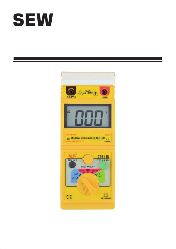
1. Instrument Layout
FUNCTION SWITCH
EXTERNAL
VOLTAGE
INDICATOR
OUTPUT
TERMINAL
LCD
DISPLAY
POWER
INDICATOR
DATA HOLD
BUTTON
TEST
BUTTON
Ω NULL
ADJUST

-2-
2. Introduction
NOTE
This meter has been designed and tested according
to IEC publication 348, safety requirements for
electronic measuring apparatus, IEC-1010 (EN
61010) and other safety standards.
Follow all warnings to ensure safe operation.
WARNING
READ "SAFETY NOTES" ( NEXT PAGE ) BEFORE
USING THE METER.
3. Safety Notes
●Read the following safety information carefully
before attempting to operate or service the meter.
● Use the meter only as specied in this manual ;
otherwise the protection provided by the meter may
be impaired.
●Rated environmental conditions :
(1) Indoor use.
(2) Installation Category III.
(3) Pollution Degree 2.
(4) Altitude up to 2000 Meter.
(5) Relative Humidity 80% Max.
(6) Ambient Temperature 0°C~40°C.

-3-
●Observe the international electrical symbols listed
below:
Meter is protected throughout by double
insulation or reinforced insulation.
Warning ! Risk of electric shock .
Caution ! Refer to this manual before using
the meter.
Alternating current.
4. Features
●3½ Digit Insulation Tester.
●68mm x 34mm ( 1.338" x 2.677") large LCD display.
●Three insulation test voltage : 250V, 500V,
1000VDC.
●The output voltage is 1000VDC.
●External voltage warning indication.
●Automatic circuit discharge.
●Test insulation at rated voltage into a 1 mA load.
●200 mA continuity short circuit test current.
●AC voltage measurement.
●Fuse protection.
●Timer for test function (count 3~5 minutes)
●Data hold function.
●Auto power off function.

-4-
●Meet EN 61010-1 CAT III 600V
EN 61326
EN 61000-4-2
EN 61000-4-3
●BS 16th edition
5. Measuring Methods
OPERATION CAUTION
Observe all safety precautions when the FUNCTION
switch is set to 250,500V,1000V position. Connect
the meter test leads to the circuit under test before
operating the TEST button. Do not touch the clip ends
of the test leads when the TEST button is pressed.
Some electrical equipment, especially cables, may
retain an electrical charge when disconnected
from the line. It is good practice to discharge such
equipment with grounding straps, or other suitable
devices, before touching or making connections. The
meter automatically discharge the test circuits when
the spring loaded TEST button is released.
IMPORTANT
Remove all power to the circuit under test when
making resistance measurements. If any voltage is
present in the test circuit the LED on the meter scale
plate will light. Immediately disconnect the test leads
and turn off power to test circuit.

-5-
●FUNCTION SWITCH :
The FUNCTION switch is used to select the range,
or function desired.
●TEST BUTTON :
The TEST button is normally OFF, press to test.
●Always check the following before testing :
The " " indicator is not showing.
There is no visual damage to the instrument or
test leads.
●Test Lead Continuity
Select the CONTINUITY function and Ω range.
Short the test leads together.
An over-range ("1") indication mean the leads
are faulty or instrument fuse is blown. (See "Fuse
Replacement" section).
●Insulation Resistance Testing:
Warning: Insulation tests should be conducted
on circuits that are de-energised.
Ensure circuits are not live before
commencing testing.
(1) Select the required test voltage (250V, 500V or
1000V) by rotating the FUNCTION switch.
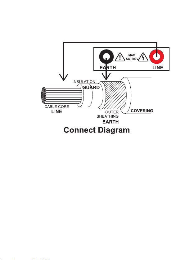
(2) Connect the test leads to the instrument and
to the circuit to be tested. (See connect
diagram). If the "LIVE CIRCUIT" is light, do
not press the TEST button and disconnect the
instrument from the circuit. The circuit is LIVE
and should be de-energised before further
testing.
-6-
(3) Press the TEST button. The value of insulation
resistance in megohms will be displayed.
Caution: Never turn the function dial while
the button is depressed. This may
damage the instrument. Never touch
the circuit during insulation testing.
When testing is complete ensure the TEST button
is released before the test leads are disconnected.
This is because the system may be charged up and
it must be allowed to discharge through the tester's
internal discharge resistor.
●Continuity discharge (Resistance tests)
Warning: Ensure circuit is not live before
commencing testing.

-7-
(1) Select the 20Ω range by rotating the FUNCTION
switch and connect the test leads to the
instrument. Short the tips of the test leads. Press
and hold down the TEST button by twisting it
clockwise.
The display will show the resistance of the
test leads. Adjust the Ω Null control to set the
reading to zero.
(2) Connect the test leads to the circuit under test.
Ensure the circuit is not live by checking that
the live circuit indicator does not light. Read the
value of resistance from the LCD.
●AC voltage test :
Set the FUNCTION switch to ACV. Connect test
leads to circuit being measured. Press TEST button
and read the value of voltage from the LCD.

-8-
6. Specications
●Insulation Resistance
Auto range: 20MΩ / 200MΩ / 2000MΩ
20MΩ
Resolution : 1 count / 10kΩ
Accuracy : ± 1.5% rdg. ± 5 dgt.
200MΩ
Resolution : 1 count / 100kΩ
Accuracy : ± 2.5% rdg. ± 3 dgt.
2000MΩ
Resolution : 1 count / 1MΩ
Accuracy : ± 5% rdg. ± 5 dgt.
Output current :
1mA DC min. at 0.25MΩ (250V range)
1mA DC min. at 0.5MΩ (500V range)
1mA DC min. at 1MΩ (1000V range)
Power consumption : Max. consumption current
approximately 250mA
●AC Voltage
Range : 0 - 600V
Resolution : 1V
Accuracy : ± 1.5% rdg. ± 3 dgt.
Line frequency range : 40 - 120 Hz.

-9-
●Continuity
Auto range :
20Ω/200Ω/2000Ω
Min Resolution :
0.01Ω
Accuracy :
± 1.5% rdg. ± 3 dgt.
Open circuit terminal voltage :
4V DC min.
Short circuit terminal current :
210mA DC min.
Power consumption :
Max. consumption current approximately 160mA
Buzzer sounds under 10Ω
●Withstand :
Meet IEC-1010 safety requirements Category III
●Dimension : 205(L) x 90(W) x 55(D) mm
●Weight : Approx. 600g ( batteries included )
●Standard Accessories :
Batteries 1.5V, size AA 6 pieces
Test Leads 1 pair
Fuse 0.5A 250V 1 piece
Instruction Manual 1 vol.
●Auto power off : Timer about 5~10 minutes
(Current consumption:10µA)

-10-
7. Maintenance
Caution : Always disconnect the test leads from
instrument before batteries or fuse
replacement.
●Batteries Replacement :
Please replace batteries when the " " indicator
Was shown on the LCD.
Disconnect the test leads from the instrument,
remove the battery compartment lid and the
batteries.
Replace with six 1.5V AA batteries, taking care to
observe correct polarity. Alkaline batteries are
recommended.
Replace the battery compartment lid.
●Fuse Replacement :
Open the battery compartment lid. Remove the fuse
cove and the old fuse, and replace with the new
one.
Replace the fuse cover and screw the battery
compartment lid before using the tester.
●Cleaning and Storage:
Periodically wipe the case with a damp cloth and
detergent; do not use abrasives or solvents.
If the meter is not to be used for periods of longer
than 60 days, remove the batteries and store them
separately.
WARNING
To avoid electrical shock or damage to the meter,
do not get water inside the case.
Table of contents
Other SEW Test Equipment manuals


Popular Test Equipment manuals by other brands


DazeTechnology
DazeTechnology EVSE AC TESTER User and installation manual

Broan
Broan ERV100SP Series installation guide

JDS Uniphase
JDS Uniphase T-BERD 6000A Getting started manual

CDP
CDP CDP8899 Operation manual

Keysight Technologies
Keysight Technologies PNA-X N524xB installation guide

Nidec
Nidec Shimpo ST-320BL Operation manual


